
P8Q77-M2 User's Manual
Page 1
P8Q77-M2 Motherboard
P8Q77-M2 Motherboard

P8Q77-M2 User's Manual
Page 3
Contents Safety information...vi About this guide...vii P8Q77-M2 specifications summary ix Package contents...xi Chapter 1: Product introduction 1.1 Special features 1-1 1.1.1 Product highlights 1-1 1.1.2 Innovative ASUS features 1-2 1.2 Before you proceed 1-3 1.3 Motherboard overview 1-4 1.3.1 Placement direction 1-4 1.3.2 Screw holes 1-4 1.3.3 Motherboard layout 1-5 1.3.4 Layout contents 1-6 1.4 Central Processing Unit (CPU 1-7 1.4.1 Installing the CPU 1-8 1.4.2 CPU heatsink and fan assembly installation 1-10 1.5 System memory 1-12...
Contents Safety information...vi About this guide...vii P8Q77-M2 specifications summary ix Package contents...xi Chapter 1: Product introduction 1.1 Special features 1-1 1.1.1 Product highlights 1-1 1.1.2 Innovative ASUS features 1-2 1.2 Before you proceed 1-3 1.3 Motherboard overview 1-4 1.3.1 Placement direction 1-4 1.3.2 Screw holes 1-4 1.3.3 Motherboard layout 1-5 1.3.4 Layout contents 1-6 1.4 Central Processing Unit (CPU 1-7 1.4.1 Installing the CPU 1-8 1.4.2 CPU heatsink and fan assembly installation 1-10 1.5 System memory 1-12...

P8Q77-M2 User's Manual
Page 6
Operation safety • Before installing the motherboard and adding devices on it may become wet. • Place the product on a stable surface. • If you detect any area where it , carefully read ... damaged. If you are not sure about the voltage of the electrical outlet you add a device. • Before connecting or removing signal cables from the motherboard, ensure that the power cables for the devices are unplugged before the signal cables are connected. Do not place the product in your area. Safety...
Operation safety • Before installing the motherboard and adding devices on it may become wet. • Place the product on a stable surface. • If you detect any area where it , carefully read ... damaged. If you are not sure about the voltage of the electrical outlet you add a device. • Before connecting or removing signal cables from the motherboard, ensure that the power cables for the devices are unplugged before the signal cables are connected. Do not place the product in your area. Safety...

P8Q77-M2 User's Manual
Page 7
... through the BIOS Setup menus. vii How this guide This user guide contains the information you need when installing and configuring the motherboard. ASUS websites The ASUS website provides updated information on ASUS hardware and software products. These documents are also provided. About this guide is organized This guide contains the following sources for...
... through the BIOS Setup menus. vii How this guide This user guide contains the information you need when installing and configuring the motherboard. ASUS websites The ASUS website provides updated information on ASUS hardware and software products. These documents are also provided. About this guide is organized This guide contains the following sources for...
P8Q77-M2 User's Manual
Page 11
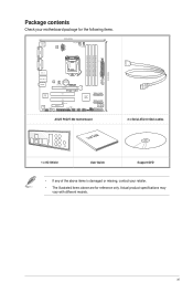
... SATA3G_4 SATA3G_3 USB3_34 ALC 887 AAFP COM1 PCIEX4_1 LPT SB_PWR DRCT CHASSIS DIS_ME USB910 USB78 64Mb 64Mb BIOS BIOS USB56 CLRTC SATA3G_2 SATA3G_1 SPEAKER F_PANEL ASUS P8Q77-M2 motherboard User Guide 2 x Serial ATA 6.0 Gb/s cables 1 x I/O-Shield User Guide Support DVD • If any of the above are for the following... CPU_FAN EATX12V DVI-D MemOK! Package contents Check your retailer. • The illustrated items above items is damaged or missing, contact your motherboard package for reference only. Actual product specifications may vary with different models.
... SATA3G_4 SATA3G_3 USB3_34 ALC 887 AAFP COM1 PCIEX4_1 LPT SB_PWR DRCT CHASSIS DIS_ME USB910 USB78 64Mb 64Mb BIOS BIOS USB56 CLRTC SATA3G_2 SATA3G_1 SPEAKER F_PANEL ASUS P8Q77-M2 motherboard User Guide 2 x Serial ATA 6.0 Gb/s cables 1 x I/O-Shield User Guide Support DVD • If any of the above are for the following... CPU_FAN EATX12V DVI-D MemOK! Package contents Check your retailer. • The illustrated items above items is damaged or missing, contact your motherboard package for reference only. Actual product specifications may vary with different models.

P8Q77-M2 User's Manual
Page 13
...for advanced operating systems. ASUS P8Q77-M2 1-1 It is the PCI Express bus standard that supports the 1155 socket Intel® 3rd/2nd generation processors. Dual-Channel DDR3 2200(O.C.) / 2000(O.C.) / 1800(O.C) / 1600 / 1333 / 1066MHz The motherboard supports the dual-channel ...MHz to boost the system's performance, and to provide efficient power management for the next-generation Serial ATA (SATA) storage interface, this motherboard delivers up to PCIe 1.0/2.0 devices. * Intel® 3rd generation Core™ processors support PCIe 3.0. Product introduction 1.1 Special features 1...
...for advanced operating systems. ASUS P8Q77-M2 1-1 It is the PCI Express bus standard that supports the 1155 socket Intel® 3rd/2nd generation processors. Dual-Channel DDR3 2200(O.C.) / 2000(O.C.) / 1800(O.C) / 1600 / 1333 / 1066MHz The motherboard supports the dual-channel ...MHz to boost the system's performance, and to provide efficient power management for the next-generation Serial ATA (SATA) storage interface, this motherboard delivers up to PCIe 1.0/2.0 devices. * Intel® 3rd generation Core™ processors support PCIe 3.0. Product introduction 1.1 Special features 1...

P8Q77-M2 User's Manual
Page 15
...using an OS-based utility. ErP Ready The motherboard is European Union's Energy-related Products (ErP) ready, and ErP requires products to meet certain energy efficiency requirement in the bag that came with ASUS vision of creating environment-friendly and energy-efficient products... the wall socket before you install motherboard components or change any motherboard settings. • Unplug the power cord from the power supply. ASUS P8Q77-M2 1-3 Failure to do so may cause severe damage to the motherboard, peripherals, or components. ASUS CrashFree BIOS 3 ASUS CrashFree BIOS 3 is an auto...
...using an OS-based utility. ErP Ready The motherboard is European Union's Energy-related Products (ErP) ready, and ErP requires products to meet certain energy efficiency requirement in the bag that came with ASUS vision of creating environment-friendly and energy-efficient products... the wall socket before you install motherboard components or change any motherboard settings. • Unplug the power cord from the power supply. ASUS P8Q77-M2 1-3 Failure to do so may cause severe damage to the motherboard, peripherals, or components. ASUS CrashFree BIOS 3 ASUS CrashFree BIOS 3 is an auto...

P8Q77-M2 User's Manual
Page 16
... rear of the chassis P8Q77-M2 1-4 Chapter 1: Product introduction The edge with external ports goes to the rear part of the chassis as indicated in the image below. 1.3.2 Screw holes Place six screws into the chassis in the correct orientation. Doing so can cause you physical injury and damage motherboard components. 1.3.1 Placement direction...
... rear of the chassis P8Q77-M2 1-4 Chapter 1: Product introduction The edge with external ports goes to the rear part of the chassis as indicated in the image below. 1.3.2 Screw holes Place six screws into the chassis in the correct orientation. Doing so can cause you physical injury and damage motherboard components. 1.3.1 Placement direction...

P8Q77-M2 User's Manual
Page 19
... damage is on the LGA1155 socket. • The product warranty does not cover damage to the PnP cap/socket contacts/motherboard components. ASUS P8Q77-M2 1-7 ASUS will process Return Merchandise Authorization (RMA) requests only if the motherboard comes with a surface mount LGA1155 socket designed for the Intel® 3rd/2nd Generation Core™ i7 / Core™...
... damage is on the LGA1155 socket. • The product warranty does not cover damage to the PnP cap/socket contacts/motherboard components. ASUS P8Q77-M2 1-7 ASUS will process Return Merchandise Authorization (RMA) requests only if the motherboard comes with a surface mount LGA1155 socket designed for the Intel® 3rd/2nd Generation Core™ i7 / Core™...

P8Q77-M2 User's Manual
Page 24
... DIMM_B2 Channel Sockets Channel A DIMM_A1 and DIMM_A2 P8Q77-M2 Channel B DIMM_B1 and DIMM_B2 P8Q77-M2 240-pin DDR3 DIMM sockets 1-12 Chapter 1: Product introduction DDR3 modules are developed for better performance with four Double Data Rate 3 (DDR3) Dual Inline Memory Modules (DIMM) sockets. 1.5 System memory 1.5.1 Overview The motherboard comes with less power consumption. A DDR3 module...
... DIMM_B2 Channel Sockets Channel A DIMM_A1 and DIMM_A2 P8Q77-M2 Channel B DIMM_B1 and DIMM_B2 P8Q77-M2 240-pin DDR3 DIMM sockets 1-12 Chapter 1: Product introduction DDR3 modules are developed for better performance with four Double Data Rate 3 (DDR3) Dual Inline Memory Modules (DIMM) sockets. 1.5 System memory 1.5.1 Overview The motherboard comes with less power consumption. A DDR3 module...

P8Q77-M2 User's Manual
Page 25
... that you install memory modules of the following: - P8Q77-M2 Motherboard Qualified Vendors Lists (QVL) DDR3-2400 (O.C.) MHz capability Vendors Part No. Timing 11-11-11-31 - Check with the retailer to get the correct memory modules. • Memory module with the same CAS latency. ASUS P8Q77-M2 1-13 To operate at the vendor-marked or...
... that you install memory modules of the following: - P8Q77-M2 Motherboard Qualified Vendors Lists (QVL) DDR3-2400 (O.C.) MHz capability Vendors Part No. Timing 11-11-11-31 - Check with the retailer to get the correct memory modules. • Memory module with the same CAS latency. ASUS P8Q77-M2 1-13 To operate at the vendor-marked or...
P8Q77-M2 User's Manual
Page 29
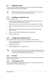
... the system unit cover (if your motherboard is completely seated on shared slots, ensure that the drivers support "Share IRQ" or that came with it by adjusting the software settings. 1. See Chapter 2 for the expansion card. ASUS P8Q77-M2 1-17 1.6 Expansion slots In the future..., you may cause you physical injury and damage motherboard components. 1.6.1 Installing an expansion card To install an expansion card: 1. Otherwise, conflicts will ...
... the system unit cover (if your motherboard is completely seated on shared slots, ensure that the drivers support "Share IRQ" or that came with it by adjusting the software settings. 1. See Chapter 2 for the expansion card. ASUS P8Q77-M2 1-17 1.6 Expansion slots In the future..., you may cause you physical injury and damage motherboard components. 1.6.1 Installing an expansion card To install an expansion card: 1. Otherwise, conflicts will ...

P8Q77-M2 User's Manual
Page 30
...; processors support PCIe 3.0. shared - - - - Intel® ME jumper (3-pin DIS_ME) This jumper allows you want to update it . Set this motherboard A B C D E F G H Intel PCH SATA controller #0 - - - P8Q77-M2 DIS_ME 12 23 Normal (Default) P8Q77-M2 Intel® ME jumper Disable ME Disable the Intel® ME function only when you to disable it . 1-18 Chapter 1: Product...
...; processors support PCIe 3.0. shared - - - - Intel® ME jumper (3-pin DIS_ME) This jumper allows you want to update it . Set this motherboard A B C D E F G H Intel PCH SATA controller #0 - - - P8Q77-M2 DIS_ME 12 23 Normal (Default) P8Q77-M2 Intel® ME jumper Disable ME Disable the Intel® ME function only when you to disable it . 1-18 Chapter 1: Product...
P8Q77-M2 User's Manual
Page 33
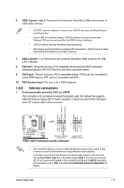
...DVI-I. 10. DVI-D can only be converted to output RGB Signal to [HD]. See section 2.5.9 Onboard Devices Configuration for your USB 3.0 devices. 7. ASUS P8Q77-M2 1-21 USB 2.0 ports 1 ~ 4. DVI-D port. Front panel audio connector (10-1 pin AAFP) This connector is for USB 2.0/1.1 devices. 8. ...SENSE_SEND PORT2 L P8Q77-M2 HD-audio-compliant Legacy AC'97 pin definition compliant definition P8Q77-M2 Front panel audio connector • We recommend that you want to connect an AC'97 front panel audio module to [AC97]. Connect one end of the motherboard's high-definition ...
...DVI-I. 10. DVI-D can only be converted to output RGB Signal to [HD]. See section 2.5.9 Onboard Devices Configuration for your USB 3.0 devices. 7. ASUS P8Q77-M2 1-21 USB 2.0 ports 1 ~ 4. DVI-D port. Front panel audio connector (10-1 pin AAFP) This connector is for USB 2.0/1.1 devices. 8. ...SENSE_SEND PORT2 L P8Q77-M2 HD-audio-compliant Legacy AC'97 pin definition compliant definition P8Q77-M2 Front panel audio connector • We recommend that you want to connect an AC'97 front panel audio module to [AC97]. Connect one end of the motherboard's high-definition ...
P8Q77-M2 User's Manual
Page 34
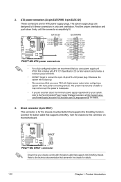
... 1 +12V DC +12V DC +12V DC +12V DC GND GND GND GND P8Q77-M2 ATX power connectors EATXPWR +3 Volts +12 Volts +12 Volts +5V Standby Power OK GND +5 Volts GND +5 Volts GND +3 Volts +3 Volts PIN 1 GND +5 Volts +5 Volts +5 Volts ... at http://support.asus. Direct connector (2-pin DRCT) This connector is inadequate. • If you use a power supply unit (PSU) that complies with the button cable that came with more power-consuming devices. P8Q77-M2 P8Q77-M2 DRCT connector Ensure that supports the DirectKey function. Refer to this connector on the motherboard. Connect the button...
... 1 +12V DC +12V DC +12V DC +12V DC GND GND GND GND P8Q77-M2 ATX power connectors EATXPWR +3 Volts +12 Volts +12 Volts +5V Standby Power OK GND +5 Volts GND +5 Volts GND +3 Volts +3 Volts PIN 1 GND +5 Volts +5 Volts +5 Volts ... at http://support.asus. Direct connector (2-pin DRCT) This connector is inadequate. • If you use a power supply unit (PSU) that complies with the button cable that came with more power-consuming devices. P8Q77-M2 P8Q77-M2 DRCT connector Ensure that supports the DirectKey function. Refer to this connector on the motherboard. Connect the button...
P8Q77-M2 User's Manual
Page 35
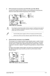
.... Chassis intrusion connector (4-1 pin CHASSIS) This connector is removed or replaced. Insufficient air flow inside the system may damage the motherboard components. CHASSIS +5VSB_MB Chassis Signal GND P8Q77-M2 P8Q77-M2 Chassis intrusion connector ASUS P8Q77-M2 1-23 Connect one end of the chassis intrusion sensor or switch cable to the fan connectors on the fan connectors! •...
.... Chassis intrusion connector (4-1 pin CHASSIS) This connector is removed or replaced. Insufficient air flow inside the system may damage the motherboard components. CHASSIS +5VSB_MB Chassis Signal GND P8Q77-M2 P8Q77-M2 Chassis intrusion connector ASUS P8Q77-M2 1-23 Connect one end of the chassis intrusion sensor or switch cable to the fan connectors on the fan connectors! •...
P8Q77-M2 User's Manual
Page 39
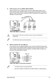
...of the chassis. Connect the USB 3.0 bracket cable to this connector, then install the USB 3.0 bracket to the USB connectors. USB3_34 P8Q77-M2 P8Q77-M2 USB3.0 Front panel connector • The USB 3.0 module is purchased separately. • Due to a slot opening at the back... USB 2.0 specification that supports up to 480 Mbps connection speed. ASUS P8Q77-M2 1-27 USB 3.0 connector (20-1 pin USB3_34) This connector is purchased separately. 13. Doing so will damage the motherboard! These USB connectors comply with ASUS USB 3.0 header, you can have a front panel USB 3.0 solution...
...of the chassis. Connect the USB 3.0 bracket cable to this connector, then install the USB 3.0 bracket to the USB connectors. USB3_34 P8Q77-M2 P8Q77-M2 USB3.0 Front panel connector • The USB 3.0 module is purchased separately. • Due to a slot opening at the back... USB 2.0 specification that supports up to 480 Mbps connection speed. ASUS P8Q77-M2 1-27 USB 3.0 connector (20-1 pin USB3_34) This connector is purchased separately. 13. Doing so will damage the motherboard! These USB connectors comply with ASUS USB 3.0 header, you can have a front panel USB 3.0 solution...

P8Q77-M2 User's Manual
Page 40
P8Q77-M2 P8Q77-M2 MemOK! switch • Refer to section 1.10 Onboard LEDs for the exact location of ...are incompatible with ones recommended in the Memory QVL (Qualified Vendors Lists) in this user manual or on the ASUS website at www.asus.com after using the MemOK! If the test fails, the system reboots and test the next set is ... BIOS default settings. switch to enhance system performance. This is ideal for successful boot. Replace the DIMMs with the motherboard may cause system boot failure, and the DRAM_LED near the MemOK! switch does not function under Windows® OS ...
P8Q77-M2 P8Q77-M2 MemOK! switch • Refer to section 1.10 Onboard LEDs for the exact location of ...are incompatible with ones recommended in the Memory QVL (Qualified Vendors Lists) in this user manual or on the ASUS website at www.asus.com after using the MemOK! If the test fails, the system reboots and test the next set is ... BIOS default settings. switch to enhance system performance. This is ideal for successful boot. Replace the DIMMs with the motherboard may cause system boot failure, and the DRAM_LED near the MemOK! switch does not function under Windows® OS ...
P8Q77-M2 User's Manual
Page 41
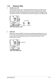
... you should shut down the system and unplug the power cable before removing or plugging in any motherboard component. DRAM LED P8Q77-M2 P8Q77-M2 DRAM LED ASUS P8Q77-M2 1-29 1.10 Onboard LEDs 1. This is solved. Standby Power LED The motherboard comes with a standby power LED that lights up to the error device will continue lighting until the...
... you should shut down the system and unplug the power cable before removing or plugging in any motherboard component. DRAM LED P8Q77-M2 P8Q77-M2 DRAM LED ASUS P8Q77-M2 1-29 1.10 Onboard LEDs 1. This is solved. Standby Power LED The motherboard comes with a standby power LED that lights up to the error device will continue lighting until the...

P8Q77-M2 User's Manual
Page 42
...OS version and corresponding updates to maximize the features of ASUS motherboard. Refer to run the Support DVD Place the Support DVD into the optical drive. To run the DVD. 1-30 Chapter 1: Product introduction Visit the ASUS website at any time without notice. Double-click the ...ASSETUP.EXE to your hardware. • Motherboard settings and hardware options vary. Click Drivers, Utilities, Make Disk, Manual, and Contact tabs...
...OS version and corresponding updates to maximize the features of ASUS motherboard. Refer to run the Support DVD Place the Support DVD into the optical drive. To run the DVD. 1-30 Chapter 1: Product introduction Visit the ASUS website at any time without notice. Double-click the ...ASSETUP.EXE to your hardware. • Motherboard settings and hardware options vary. Click Drivers, Utilities, Make Disk, Manual, and Contact tabs...


