
User Guide
Page 13
... 32/64bit ATX Form Factor, 12"x 9.6" (30.5cm x 24.5cm) *Specifications are subject to change without notice. P8P67 WS Revolution specifications summary Internal I/O Connectors Manageability OS Form Factor 24-pin ATX Power connector 8-pin ATX +12V Power connector 4pin EZ_PLUG Power connector CPU fan with PWM control Chassis fan1 with Q-fan control Chassis fan2 with Q-fan control Chassis...
... 32/64bit ATX Form Factor, 12"x 9.6" (30.5cm x 24.5cm) *Specifications are subject to change without notice. P8P67 WS Revolution specifications summary Internal I/O Connectors Manageability OS Form Factor 24-pin ATX Power connector 8-pin ATX +12V Power connector 4pin EZ_PLUG Power connector CPU fan with PWM control Chassis fan1 with Q-fan control Chassis fan2 with Q-fan control Chassis...
User Guide
Page 41
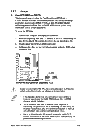
... RAM, never remove the cap on pins 2-3 for about 5-10 seconds, then move the jumper again to clear the CMOS RTC RAM data. Shut down the key during the boot process and enter BIOS setup to overclocking. ASUS P8P67 WS Revolution 2-15 Turn OFF the computer and unplug the power cord. 2. Removing the cap will cause...
... RAM, never remove the cap on pins 2-3 for about 5-10 seconds, then move the jumper again to clear the CMOS RTC RAM data. Shut down the key during the boot process and enter BIOS setup to overclocking. ASUS P8P67 WS Revolution 2-15 Turn OFF the computer and unplug the power cord. 2. Removing the cap will cause...

User Guide
Page 48
...caps on the motherboard, ensuring that you install two VGA cards, we recommend that the black wire of each cable matches the ground pin of maximum 2A (24 W) fan power. • If you plug the rear chassis fan cable to the fan connectors. These are not jumpers! 7. CPU, chassis,... and power fan connectors (4-pin CPU_FAN; 4-pin CHA_FAN1/2/3; 3-pin PWR_FAN) Connect the fan cables to the fan connectors on the fan connectors! • The CPU_FAN connector supports the CPU fan of ...
...caps on the motherboard, ensuring that you install two VGA cards, we recommend that the black wire of each cable matches the ground pin of maximum 2A (24 W) fan power. • If you plug the rear chassis fan cable to the fan connectors. These are not jumpers! 7. CPU, chassis,... and power fan connectors (4-pin CPU_FAN; 4-pin CHA_FAN1/2/3; 3-pin PWR_FAN) Connect the fan cables to the fan connectors on the fan connectors! • The CPU_FAN connector supports the CPU fan of ...

User Guide
Page 50
TPM connector (20-1 pin TPM) This connector supports a Trusted Platform Module (TPM) system, which can also serve for G.P. Diagnosis card layout LED 0 and 1 Power Switch. Press to turn ON or OFF the computer. This connector can securely store keys, digital certificates, passwords, and data. Card connector 2-24 Chapter 2: Hardware information Diagnosis card installtion. Press to restart the computer. A TPM system also helps enhance network security, protects digital identities, and ensures platform integrity. Reset Button. 10. G.P.
TPM connector (20-1 pin TPM) This connector supports a Trusted Platform Module (TPM) system, which can also serve for G.P. Diagnosis card layout LED 0 and 1 Power Switch. Press to turn ON or OFF the computer. This connector can securely store keys, digital certificates, passwords, and data. Card connector 2-24 Chapter 2: Hardware information Diagnosis card installtion. Press to restart the computer. A TPM system also helps enhance network security, protects digital identities, and ensures platform integrity. Reset Button. 10. G.P.

User Guide
Page 51
...S3 S4 S5 Resume from S1 Resume from S3 Resume from S4 ASUS P8P67 WS Revolution 2-25 Installing G.P. With the LEDs of the diagnosis card facing to avoid electrical shock hazard. 1. Diagnosis card Ensure to turn off the power supply unit before installing the diagnosis card to the PCIe slots, ...align the card connector with the TPM connector and press firmly until the card sits on the motherboard. 2. Locate the TPM connector (20-1 pin TPM) on the connector completely. Diagnosis...
...S3 S4 S5 Resume from S1 Resume from S3 Resume from S4 ASUS P8P67 WS Revolution 2-25 Installing G.P. With the LEDs of the diagnosis card facing to avoid electrical shock hazard. 1. Diagnosis card Ensure to turn off the power supply unit before installing the diagnosis card to the PCIe slots, ...align the card connector with the TPM connector and press firmly until the card sits on the motherboard. 2. Locate the TPM connector (20-1 pin TPM) on the connector completely. Diagnosis...

User Guide
Page 52
... not boot. • Use of 350 W. • Do not forget to connect the 8-pin EATX12 V power plug; The power supply plugs are uncertain about the minimum power supply requirement for your system, refer to fit these connectors in only one orientation. Find the... stability. 2-26 Chapter 2: Hardware information 11. ATX power connectors (24-pin EATXPWR; 8-pin EATX12V; 4-pin EZ_PLUG) These connectors are for details. • If you are designed to the Recommended Power Supply Wattage Calculator at http://support.asus.com/PowerSupplyCalculator/PSCalculator. aspx?SLanguage=en-us for ATX...
... not boot. • Use of 350 W. • Do not forget to connect the 8-pin EATX12 V power plug; The power supply plugs are uncertain about the minimum power supply requirement for your system, refer to fit these connectors in only one orientation. Find the... stability. 2-26 Chapter 2: Hardware information 11. ATX power connectors (24-pin EATXPWR; 8-pin EATX12V; 4-pin EZ_PLUG) These connectors are for details. • If you are designed to the Recommended Power Supply Wattage Calculator at http://support.asus.com/PowerSupplyCalculator/PSCalculator. aspx?SLanguage=en-us for ATX...

User Guide
Page 53
... cable to the HDD. • System warning speaker (4-pin SPEAKER) This 4-pin connector is for the HDD Activity LED. The IDE LED lights up when you to this connector. ASUS P8P67 WS Revolution 2-27 Pressing the power button turns the system on the BIOS settings. 12. Connect the chassis power LED cable to hear system beeps and warnings...
... cable to the HDD. • System warning speaker (4-pin SPEAKER) This 4-pin connector is for the HDD Activity LED. The IDE LED lights up when you to this connector. ASUS P8P67 WS Revolution 2-27 Pressing the power button turns the system on the BIOS settings. 12. Connect the chassis power LED cable to hear system beeps and warnings...

User Guide
Page 160
... components you installed. 5-12 Chapter 5: Multiple GPU technology support Refer to install the device drivers. 7. The screen differs based on the slot. 4. 3. Connect either one 8-pin power connector or two 6-pin power connectors from the menu. To verify graphics card driver installation, right-click My Computer and select Properties from the...
... components you installed. 5-12 Chapter 5: Multiple GPU technology support Refer to install the device drivers. 7. The screen differs based on the slot. 4. 3. Connect either one 8-pin power connector or two 6-pin power connectors from the menu. To verify graphics card driver installation, right-click My Computer and select Properties from the...


