User Manual
Page 13
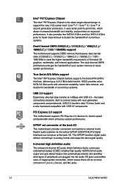
... new features and latest technologies, making it , check the items in your motherboard package for buying an ASUS® P8P67-M PRO motherboard! This provides great graphics performance. Before you for the following items. Motherboard Cables Accessories Application DVD Documentation ASUS P8P67-M PRO motherboard 2 x Serial ATA 3.0Gb/s cables 2 x Serial ATA 6.0Gb/s cables 1 x Q-shield 1 x Q-Connector (retail version only...
... new features and latest technologies, making it , check the items in your motherboard package for buying an ASUS® P8P67-M PRO motherboard! This provides great graphics performance. Before you for the following items. Motherboard Cables Accessories Application DVD Documentation ASUS P8P67-M PRO motherboard 2 x Serial ATA 3.0Gb/s cables 2 x Serial ATA 6.0Gb/s cables 1 x Q-shield 1 x Q-Connector (retail version only...
User Manual
Page 14
...stability, and provides an improved performance. It uses serial point-to meet the higher bandwidth requirements of Line-in, Line-out, and Mic jacks. 1-2 ASUS P8P67-M PRO S/PDIF out connector at the back I/O This motherboard provides convenient connectivity to boost system performance. the latest connectivity standard. The S/PDIF transfers digital audio... / 1600(O.C.) / 1333 / 1066 MHz to -point links, which means there will be no more confusion of the latest 3D graphics, multimedia, and Internet applications. ASUS provides extra SATA 6.0 Gb/s ports with USB 2.0 components.
...stability, and provides an improved performance. It uses serial point-to meet the higher bandwidth requirements of Line-in, Line-out, and Mic jacks. 1-2 ASUS P8P67-M PRO S/PDIF out connector at the back I/O This motherboard provides convenient connectivity to boost system performance. the latest connectivity standard. The S/PDIF transfers digital audio... / 1600(O.C.) / 1333 / 1066 MHz to -point links, which means there will be no more confusion of the latest 3D graphics, multimedia, and Internet applications. ASUS provides extra SATA 6.0 Gb/s ports with USB 2.0 components.

User Manual
Page 16
...a corrupted BIOS file using the bundled support DVD or USB flash disk that contains the latest BIOS file. 1-4 ASUS P8P67-M PRO Combined with usability and aesthetics, the ASUS Wing Heatsink will give users an extremely silent and cooling experience with Auto Tuning! This tool also provides stability testing... The built-in different geographic regions and your favorite photo into one software offers diverse and ease to use software package. ASUS CrashFree BIOS 3 ASUS CrashFree BIOS 3 is an auto-recovery tool that allows you to adjust the CPU and chassis fan speeds according to use...
...a corrupted BIOS file using the bundled support DVD or USB flash disk that contains the latest BIOS file. 1-4 ASUS P8P67-M PRO Combined with usability and aesthetics, the ASUS Wing Heatsink will give users an extremely silent and cooling experience with Auto Tuning! This tool also provides stability testing... The built-in different geographic regions and your favorite photo into one software offers diverse and ease to use software package. ASUS CrashFree BIOS 3 ASUS CrashFree BIOS 3 is an auto-recovery tool that allows you to adjust the CPU and chassis fan speeds according to use...

User Manual
Page 18
... you install the motherboard, study the configuration of the chassis as indicated in the correct orientation. Place this side towards the rear of the chassis P8P67-M PRO 1-6 ASUS P8P67-M PRO
... you install the motherboard, study the configuration of the chassis as indicated in the correct orientation. Place this side towards the rear of the chassis P8P67-M PRO 1-6 ASUS P8P67-M PRO
User Manual
Page 22
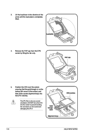
... damaging the CPU! Position the CPU over the socket, ensuring that the gold triangle is completely lifted. Gold triangle mark Alignment keys CPU notches 1-10 ASUS P8P67-M PRO Remove the PnP cap from the CPU socket by lifting the tab only. The CPU fits in the direction of the socket, and then fit...
... damaging the CPU! Position the CPU over the socket, ensuring that the gold triangle is completely lifted. Gold triangle mark Alignment keys CPU notches 1-10 ASUS P8P67-M PRO Remove the PnP cap from the CPU socket by lifting the tab only. The CPU fits in the direction of the socket, and then fit...
User Manual
Page 24
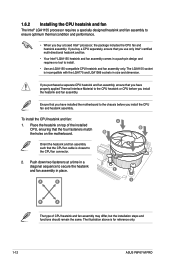
... LGA1155-compatible CPU heatsink and fan assembly only. A B 1 1 B A The type of the installed CPU, ensuring that the CPU fan cable is for reference only. 1-12 ASUS P8P67-M PRO To install the CPU heatsink and fan: A 1. Place the heatsink on top of CPU heatsink and fan assembly may differ, but the installation steps and...
... LGA1155-compatible CPU heatsink and fan assembly only. A B 1 1 B A The type of the installed CPU, ensuring that the CPU fan cable is for reference only. 1-12 ASUS P8P67-M PRO To install the CPU heatsink and fan: A 1. Place the heatsink on top of CPU heatsink and fan assembly may differ, but the installation steps and...
User Manual
Page 26
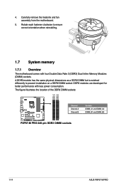
... a DDR2 DIMM socket. The figure illustrates the location of the DDR3 DIMM sockets: DIMM_A1 DIMM_A2 DIMM_B1 DIMM_B2 P8P67-M PRO Channel Channel A Channel B Sockets DIMM_A1 and DIMM_A2 DIMM_B1 and DIMM_B2 P8P67-M PRO 240-pin DDR3 DIMM sockets 1-14 ASUS P8P67-M PRO 4. Carefully remove the heatsink and fan assembly from the motherboard. 5. A DDR3 module has the same physical dimensions...
... a DDR2 DIMM socket. The figure illustrates the location of the DDR3 DIMM sockets: DIMM_A1 DIMM_A2 DIMM_B1 DIMM_B2 P8P67-M PRO Channel Channel A Channel B Sockets DIMM_A1 and DIMM_A2 DIMM_B1 and DIMM_B2 P8P67-M PRO 240-pin DDR3 DIMM sockets 1-14 ASUS P8P67-M PRO 4. Carefully remove the heatsink and fan assembly from the motherboard. 5. A DDR3 module has the same physical dimensions...
User Manual
Page 32
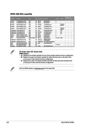
Visit the ASUS website at www.asus.com for the latest QVL. 1-20 ASUS P8P67-M PRO DDR3-1066 MHz capability Vendors Part No. Size SS/ DS Chip Brand Chip NO. SS: Single-sided / DS: Double-sided DIMM support: • A*: Supports one ...
Visit the ASUS website at www.asus.com for the latest QVL. 1-20 ASUS P8P67-M PRO DDR3-1066 MHz capability Vendors Part No. Size SS/ DS Chip Brand Chip NO. SS: Single-sided / DS: Double-sided DIMM support: • A*: Supports one ...
User Manual
Page 34
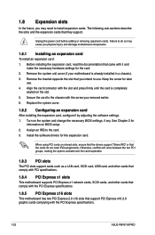
... with the PCI Express specifications. 1.8.5 PCI Express x16 slots This motherboard has two PCI Express 2.0 x16 slots that came with the PCI Express specifications. 1-22 ASUS P8P67-M PRO
... with the PCI Express specifications. 1.8.5 PCI Express x16 slots This motherboard has two PCI Express 2.0 x16 slots that came with the PCI Express specifications. 1-22 ASUS P8P67-M PRO
User Manual
Page 36
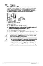
... RTC when the system hangs due to overclocking. Hold down and reboot the system, then the BIOS automatically resets parameter settings to default values. 1-24 ASUS P8P67-M PRO You can clear the CMOS memory of date, time, and system setup parameters by erasing the CMOS RTC RAM data.... P8P67-M PRO CLRTC 12 23 Normal (Default) Clear RTC P8P67-M PRO Clear RTC RAM To erase the RTC RAM: 1. For system failure due to pins 2-3. 1.9 Jumpers Clear RTC RAM (3-pin CLRTC) This jumper allows you...
... RTC when the system hangs due to overclocking. Hold down and reboot the system, then the BIOS automatically resets parameter settings to default values. 1-24 ASUS P8P67-M PRO You can clear the CMOS memory of date, time, and system setup parameters by erasing the CMOS RTC RAM data.... P8P67-M PRO CLRTC 12 23 Normal (Default) Clear RTC P8P67-M PRO Clear RTC RAM To erase the RTC RAM: 1. For system failure due to pins 2-3. 1.9 Jumpers Clear RTC RAM (3-pin CLRTC) This jumper allows you...
User Manual
Page 38
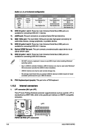
... PC-compatible computers. LPT AFD ERR# INIT# SLIN# GND GND GND GND GND GND GND GND 1-26 P8P67-M PRO P8P67-M PRO LPT connector PIN 1 STB# PD0 PD1 PD2 PD3 PD4 PD5 PD6 PD7 ACK# BUSY PE SLCT ASUS P8P67-M PRO These two 4-pin Universal Serial Bus (USB) ports are available for audio/video devices, storage peripherals, or...
... PC-compatible computers. LPT AFD ERR# INIT# SLIN# GND GND GND GND GND GND GND GND 1-26 P8P67-M PRO P8P67-M PRO LPT connector PIN 1 STB# PD0 PD1 PD2 PD3 PD4 PD5 PD6 PD7 ACK# BUSY PE SLCT ASUS P8P67-M PRO These two 4-pin Universal Serial Bus (USB) ports are available for audio/video devices, storage peripherals, or...
User Manual
Page 40
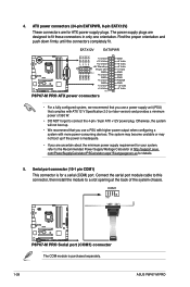
...proper orientation and push down firmly until the connectors completely fit. EATX12V EATXPWR +12V DC +12V DC +12V DC +12V DC P8P67-M PRO GND GND GND GND +3 Volts +12 Volts +12 Volts +5V Standby Power OK PIN 1 GND +5 Volts GND +5 Volts GND +3 Volts +3...the power is inadequate. • If you are designed to a slot opening at http://support.asus. Serial port connector (10-1 pin COM1) This connector is purchased separately. 1-28 ASUS P8P67-M PRO COM1 PIN 1 P8P67-M PRO P8P67-M PRO Serial port (COM1) connector The COM module is for your system, refer to connect the 4-...
...proper orientation and push down firmly until the connectors completely fit. EATX12V EATXPWR +12V DC +12V DC +12V DC +12V DC P8P67-M PRO GND GND GND GND +3 Volts +12 Volts +12 Volts +5V Standby Power OK PIN 1 GND +5 Volts GND +5 Volts GND +3 Volts +3...the power is inadequate. • If you are designed to a slot opening at http://support.asus. Serial port connector (10-1 pin COM1) This connector is purchased separately. 1-28 ASUS P8P67-M PRO COM1 PIN 1 P8P67-M PRO P8P67-M PRO Serial port (COM1) connector The COM module is for your system, refer to connect the 4-...
User Manual
Page 42
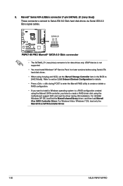
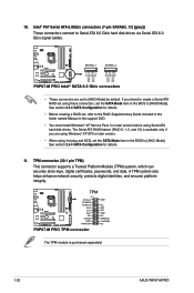
Marvell® Serial ATA 6.0Gb/s connector (7-pin SATA6G_E1 [navy blue]) These connectors connect to [AHCI Mode]. SATA6G_E1 P8P67-M PRO P8P67-M PRO Marvell® SATA 6.0 Gb/s connector • The SATA6G_E1 (navy blue) connector is not supported. • You must...then load Marvell 91xx SATA Controller Driver. For Windows Vista / Windows 7 OS, load only the Marvell 91xx SATA Controller Driver. 1-30 ASUS P8P67-M PRO Refer to section 2.5.6 Onboard Devices Configuration for data drives only. GND RSATA_RXN1 RSATA_RXP1 GND RSATA_TXN1 RSATA_TXP1 GND 8. ATAPI device is for details....
Marvell® Serial ATA 6.0Gb/s connector (7-pin SATA6G_E1 [navy blue]) These connectors connect to [AHCI Mode]. SATA6G_E1 P8P67-M PRO P8P67-M PRO Marvell® SATA 6.0 Gb/s connector • The SATA6G_E1 (navy blue) connector is not supported. • You must...then load Marvell 91xx SATA Controller Driver. For Windows Vista / Windows 7 OS, load only the Marvell 91xx SATA Controller Driver. 1-30 ASUS P8P67-M PRO Refer to section 2.5.6 Onboard Devices Configuration for data drives only. GND RSATA_RXN1 RSATA_RXP1 GND RSATA_TXN1 RSATA_TXP1 GND 8. ATAPI device is for details....
User Manual
Page 44
... these connectors, set the SATA Mode item in the BIOS to [RAID Mode]. The Serial ATA RAID feature (RAID 0, 1, 5, and 10) is purchased separately! 1-32 ASUS P8P67-M PRO TPM P8P67-M PRO PIN 1 PCICLK FRAME# PCIRST# AD3 3.3V AD0 NC 3.3VSB GND PWRDW# GND NC AD2 AD1 GND NC SERIRQ# CLKRUN# NC... P8P67-M PRO TPM connector The TPM module is available only if you intend to [AHCI Mode] by default. 10. A TPM system also helps enhance network security, protects ...
... these connectors, set the SATA Mode item in the BIOS to [RAID Mode]. The Serial ATA RAID feature (RAID 0, 1, 5, and 10) is purchased separately! 1-32 ASUS P8P67-M PRO TPM P8P67-M PRO PIN 1 PCICLK FRAME# PCIRST# AD3 3.3V AD0 NC 3.3VSB GND PWRDW# GND NC AD2 AD1 GND NC SERIRQ# CLKRUN# NC... P8P67-M PRO TPM connector The TPM module is available only if you intend to [AHCI Mode] by default. 10. A TPM system also helps enhance network security, protects ...
User Manual
Page 46
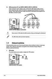
TPU P8P67-M PRO P8P67-M PRO TPU switch 1-34 ASUS P8P67-M PRO The USB module cable is ideal for USB 2.0 ports. These USB ...+5V USB_P10USB_P10+ GND NC USB+5V USB_P12USB_P12+ GND NC USB+5V USB_P14USB_P14+ GND NC P8P67-M PRO PIN 1 PIN 1 PIN 1 PIN 1 USB+5V USB_P7USB_P7+ GND USB+5V USB_P9USB_P9+ GND USB+5V USB_P11USB_P11+ GND USB...+5V USB_P13USB_P13+ GND P8P67-M PRO USB2.0 connectors Never connect a 1394 cable to a slot opening at the back of the system chassis. USB connectors...
TPU P8P67-M PRO P8P67-M PRO TPU switch 1-34 ASUS P8P67-M PRO The USB module cable is ideal for USB 2.0 ports. These USB ...+5V USB_P10USB_P10+ GND NC USB+5V USB_P12USB_P12+ GND NC USB+5V USB_P14USB_P14+ GND NC P8P67-M PRO PIN 1 PIN 1 PIN 1 PIN 1 USB+5V USB_P7USB_P7+ GND USB+5V USB_P9USB_P9+ GND USB+5V USB_P11USB_P11+ GND USB...+5V USB_P13USB_P13+ GND P8P67-M PRO USB2.0 connectors Never connect a 1394 cable to a slot opening at the back of the system chassis. USB connectors...
User Manual
Page 48
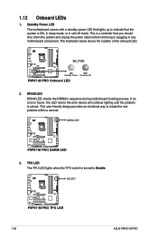
... provides an intuitional way to Enable. The illustration below shows the location of the onboard LED. SB_PWR P8P67-M PRO ON OFF Standby Power Powered Off P8P67-M PRO Onboard LED 2. O2LED1 P8P67-M PRO P8P67-M PRO TPU LED 1-36 ASUS P8P67-M PRO 1.12 Onboard LEDs 1. DARM LED P8P67-M PRO P8P67-M PRO DARM LED 3. This is a reminder that lights up to the error device will continue lighting until...
... provides an intuitional way to Enable. The illustration below shows the location of the onboard LED. SB_PWR P8P67-M PRO ON OFF Standby Power Powered Off P8P67-M PRO Onboard LED 2. O2LED1 P8P67-M PRO P8P67-M PRO TPU LED 1-36 ASUS P8P67-M PRO 1.12 Onboard LEDs 1. DARM LED P8P67-M PRO P8P67-M PRO DARM LED 3. This is a reminder that lights up to the error device will continue lighting until...
User Manual
Page 52
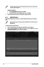
... Advanced Mode of updating itself through the Internet. Go to the Tool menu to select ASUS EZ Flash Utility and press to the USB port. 2. ASUSTek EZ Flash 2 BIOS ROM Utility V00.75 Flash Info MODEL: P8P67-M PRO File Path: fs0:\ Drive fs0:\ VER: 0202 Folder Info 10/18/10 10:23p ... File Info MODEL: Help Info VER: DATE [Enter] Select or Load [Tab] Switch [Up/Down/PageUp/PageDown/Home/End] Move [Esc] Exit 2-2 ASUS P8P67-M PRO Locate the BIOS file from file, then click Next. Select Update BIOS from the Open window, then click Open. 3. b. Insert the USB flash disk that ...
... Advanced Mode of updating itself through the Internet. Go to the Tool menu to select ASUS EZ Flash Utility and press to the USB port. 2. ASUSTek EZ Flash 2 BIOS ROM Utility V00.75 Flash Info MODEL: P8P67-M PRO File Path: fs0:\ Drive fs0:\ VER: 0202 Folder Info 10/18/10 10:23p ... File Info MODEL: Help Info VER: DATE [Enter] Select or Load [Tab] Switch [Up/Down/PageUp/PageDown/Home/End] Move [Esc] Exit 2-2 ASUS P8P67-M PRO Locate the BIOS file from file, then click Next. Select Update BIOS from the Open window, then click Open. 3. b. Insert the USB flash disk that ...
User Manual
Page 54
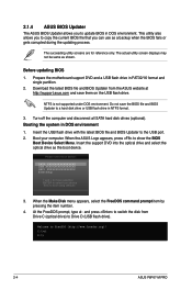
... and save the BIOS file and BIOS Updater to a hard disk drive or USB flash drive in DOS environment. C:\>d: D:\> 2-4 ASUS P8P67-M PRO Do not save them on the USB flash drive. Please select boot device: SATA: XXXXXXXXXXXXXXXX USB XXXXXXXXXXXXXXXXX UEFI: XXXXXXXXXXXXXXXX Enter Setup ↑ and ... file and BIOS Updater to boot using defaults 3. The actual utility screen displays may not be same as the boot device. 2.1.4 ASUS BIOS Updater The ASUS BIOS Updater allows you can use as a backup when the BIOS fails or gets corrupted during the updating process. Download the latest ...
... and save the BIOS file and BIOS Updater to a hard disk drive or USB flash drive in DOS environment. C:\>d: D:\> 2-4 ASUS P8P67-M PRO Do not save them on the USB flash drive. Please select boot device: SATA: XXXXXXXXXXXXXXXX USB XXXXXXXXXXXXXXXXX UEFI: XXXXXXXXXXXXXXXX Enter Setup ↑ and ... file and BIOS Updater to boot using defaults 3. The actual utility screen displays may not be same as the boot device. 2.1.4 ASUS BIOS Updater The ASUS BIOS Updater allows you can use as a backup when the BIOS fails or gets corrupted during the updating process. Download the latest ...
User Manual
Page 56
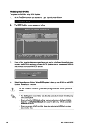
...Restart your computer. Select the Load Optimized Defaults item under the Exit menu. Refer to section 2.9 Exit menu for DOS V1.18 Current ROM BOARD: P8P67-M PRO VER: 0202 DATE: 10/18/2010 Update ROM BOARD: Unknown VER: Unknown DATE: Unknown PATH: A:\ A: P8P67MP.ROM 4194304 2010-10-18 17:30... /pc /g and press . Select Yes and press . Are you to the DOS prompt after updating the BIOS file if you have disconnected them. 2-6 ASUS P8P67-M PRO When BIOS update is done, press to select the BIOS file and press . DO NOT shut down or reset the system while updating the BIOS...
...Restart your computer. Select the Load Optimized Defaults item under the Exit menu. Refer to section 2.9 Exit menu for DOS V1.18 Current ROM BOARD: P8P67-M PRO VER: 0202 DATE: 10/18/2010 Update ROM BOARD: Unknown VER: Unknown DATE: Unknown PATH: A:\ A: P8P67MP.ROM 4194304 2010-10-18 17:30... /pc /g and press . Select Yes and press . Are you to the DOS prompt after updating the BIOS file if you have disconnected them. 2-6 ASUS P8P67-M PRO When BIOS update is done, press to select the BIOS file and press . DO NOT shut down or reset the system while updating the BIOS...
User Manual
Page 58
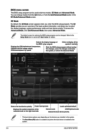
... Exit/Advanced Mode, then select Advanced Mode. EZ Mode By default, the EZ Mode screen appears when you to the system. 2-8 ASUS P8P67-M PRO EZ Mode Friday [10/08/2010] P8P67-M PRO BIOS Version : 0202 CPU Type : Genuine Intel(R) CPU 0 @ 3.10GHz Total Memory : 1024 MB (DDR3 1333MHz) Exit/Advanced Mode...or enters the Advanced Mode EFI BIOS Utility - Selects the display language of the selected mode on the right hand side Normal mode ASUS Optimal mode Selects the boot device priority • The boot device options vary depending on the devices you installed to the system. ...
... Exit/Advanced Mode, then select Advanced Mode. EZ Mode By default, the EZ Mode screen appears when you to the system. 2-8 ASUS P8P67-M PRO EZ Mode Friday [10/08/2010] P8P67-M PRO BIOS Version : 0202 CPU Type : Genuine Intel(R) CPU 0 @ 3.10GHz Total Memory : 1024 MB (DDR3 1333MHz) Exit/Advanced Mode...or enters the Advanced Mode EFI BIOS Utility - Selects the display language of the selected mode on the right hand side Normal mode ASUS Optimal mode Selects the boot device priority • The boot device options vary depending on the devices you installed to the system. ...


