
User Manual
Page 13
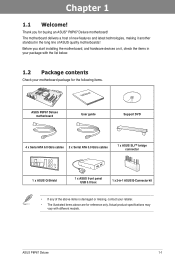
... list below. 1.2 Package contents Check your motherboard package for the following items. User Manual ASUS P8P67 Deluxe motherboard User guide Support DVD 4 x Serial ATA 6.0 Gb/s cables 2 x Serial ATA 3.0 Gb/s cables 1 x ASUS SLI™ bridge connector 1 x ASUS Q-Shield 1 x ASUS front panel USB 3.0 box 1 x 2-in-1 ASUS Q-Connector kit • If any of new features and latest technologies, making it...
... list below. 1.2 Package contents Check your motherboard package for the following items. User Manual ASUS P8P67 Deluxe motherboard User guide Support DVD 4 x Serial ATA 6.0 Gb/s cables 2 x Serial ATA 3.0 Gb/s cables 1 x ASUS SLI™ bridge connector 1 x ASUS Q-Shield 1 x ASUS front panel USB 3.0 box 1 x 2-in-1 ASUS Q-Connector kit • If any of new features and latest technologies, making it...

User Manual
Page 15
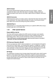
... flexibility and perfect precision to ensure optimized performance, extreme system stability, and greater power efficiency. 2X Precise Power Control ASUS DIGI+ VRM delivers twice the precision power, intelligently adjusting PWM voltage and frequency modulation to enhance system stability through enabling... additional adapter. DIGI+ VRM The new ASUS DIGI+ VRM design upgrades motherboard power delivery to Bluetooth devices with DIGI+ VRM digital power design launch control into the world's first real-time PC power saving chip through enabling VRM spread spectrum. ASUS P8P67 Deluxe 1-3
... flexibility and perfect precision to ensure optimized performance, extreme system stability, and greater power efficiency. 2X Precise Power Control ASUS DIGI+ VRM delivers twice the precision power, intelligently adjusting PWM voltage and frequency modulation to enhance system stability through enabling... additional adapter. DIGI+ VRM The new ASUS DIGI+ VRM design upgrades motherboard power delivery to Bluetooth devices with DIGI+ VRM digital power design launch control into the world's first real-time PC power saving chip through enabling VRM spread spectrum. ASUS P8P67 Deluxe 1-3
User Manual
Page 17
... UltraPC delivers exceptional 5.1 surround experience through product design and innovation to use external SATA devices without the usual "fingers" - ASUS P8P67 Deluxe 1-5 making it against static electricity and shields it convenient and easy to install. The cable is a user-friendly utility that... and power source together, allowing you to easily connect or disconnect the chassis front panel cables to energy consumptions. ASUS Q-Connector ASUS Q-Connector allows you to reduce carbon footprint of the product and thus mitigate environmental impacts. This is European Union's...
... UltraPC delivers exceptional 5.1 surround experience through product design and innovation to use external SATA devices without the usual "fingers" - ASUS P8P67 Deluxe 1-5 making it against static electricity and shields it convenient and easy to install. The cable is a user-friendly utility that... and power source together, allowing you to easily connect or disconnect the chassis front panel cables to energy consumptions. ASUS Q-Connector ASUS Q-Connector allows you to reduce carbon footprint of the product and thus mitigate environmental impacts. This is European Union's...

User Manual
Page 19
ASUS P8P67 Deluxe 2-1 Failure to do so may cause severe damage to avoid touching the ICs on them. • Whenever you uninstall any component, place it on a grounded ...
ASUS P8P67 Deluxe 2-1 Failure to do so may cause severe damage to avoid touching the ICs on them. • Whenever you uninstall any component, place it on a grounded ...

User Manual
Page 23
A DDR3 module is notched differently from a DDR or DDR2 module. DO NOT install a DDR or DDR2 memory module to the DDR3 slot. Recommended memory configurations Chapter 2 ASUS P8P67 Deluxe 2-5 2.2.3 System memory The motherboard comes with four Double Data Rate 3 (DDR3) Dual Inline Memory Modules (DIMM) slots.
A DDR3 module is notched differently from a DDR or DDR2 module. DO NOT install a DDR or DDR2 memory module to the DDR3 slot. Recommended memory configurations Chapter 2 ASUS P8P67 Deluxe 2-5 2.2.3 System memory The motherboard comes with four Double Data Rate 3 (DDR3) Dual Inline Memory Modules (DIMM) slots.

User Manual
Page 25
...) 1 DIMM 2 DIMM 4 DIMM • • • • • • • • • • • • • • • • • • • P8P67 Deluxe Motherboard Qualified Vendors Lists (QVL) DDR3 1866(O.C.) MHz capability Vendor Part No. Timing Apacer 78.AAGD5.9KD(XMP) 6GB(3 x 2GB) DS - - Crucial BL12864BE2009.8SFB3(EPP...; • • 1.65 • • 1.65 • • • 1.65 • • • 1.65 • • 1.65 • • • 1.65 • • ASUS P8P67 Deluxe 2-7
...) 1 DIMM 2 DIMM 4 DIMM • • • • • • • • • • • • • • • • • • • P8P67 Deluxe Motherboard Qualified Vendors Lists (QVL) DDR3 1866(O.C.) MHz capability Vendor Part No. Timing Apacer 78.AAGD5.9KD(XMP) 6GB(3 x 2GB) DS - - Crucial BL12864BE2009.8SFB3(EPP...; • • 1.65 • • 1.65 • • • 1.65 • • • 1.65 • • 1.65 • • • 1.65 • • ASUS P8P67 Deluxe 2-7

User Manual
Page 31
...) VGA configuration Single VGA/PCIe card Dual VGA/PCIe card PCI Express operating mode PCIe 2.0 x16_1 x16 (Recommend for single VGA) x8 PCIe 2.0 x16_2 N/A x8 ASUS P8P67 Deluxe 2-13 Chapter 2 1 2 3 ® 4 P8P67 DELUXE 5 6 7 RESET Slot No. 2.2.4 Expansion slots Ensure to do so may cause you physical injury and damage motherboard components.
...) VGA configuration Single VGA/PCIe card Dual VGA/PCIe card PCI Express operating mode PCIe 2.0 x16_1 x16 (Recommend for single VGA) x8 PCIe 2.0 x16_2 N/A x8 ASUS P8P67 Deluxe 2-13 Chapter 2 1 2 3 ® 4 P8P67 DELUXE 5 6 7 RESET Slot No. 2.2.4 Expansion slots Ensure to do so may cause you physical injury and damage motherboard components.

User Manual
Page 33
Reset switch Press the reset switch to a power source indicating that allows you to enhance system performance. 1. Chapter 2 ASUS P8P67 Deluxe 2-15 The illustration below shows the location of the onboard power-on a bare or opencase system. The switch also lights up the system. Power-on ...
Reset switch Press the reset switch to a power source indicating that allows you to enhance system performance. 1. Chapter 2 ASUS P8P67 Deluxe 2-15 The illustration below shows the location of the onboard power-on a bare or opencase system. The switch also lights up the system. Power-on ...

User Manual
Page 35
... to Enable. However, the system will use the last setting you change the switch setting to section 2.2.6 Onboard LEDs for fast, yet stable clock speeds. ASUS P8P67 Deluxe 2-17 Refer to Enable under the OS environment, the TPU function will automatically optimize the system for the exact location of the TPU LED. •...
... to Enable. However, the system will use the last setting you change the switch setting to section 2.2.6 Onboard LEDs for fast, yet stable clock speeds. ASUS P8P67 Deluxe 2-17 Refer to Enable under the OS environment, the TPU function will automatically optimize the system for the exact location of the TPU LED. •...

User Manual
Page 37
This user-friendly design provides an intuitional way to the error device will continue lighting until the problem is found , the LED next to locate the root problem within a second. 2. If an error is solved. ID LEDs The ID LEDs provide an elegant embellishment to the motherboard design. POST State LEDs The POST State LEDs of CPU, DRAM, VGA card, and HDD indicate key components status during POST (Power-on Self Test). Chapter 2 ASUS P8P67 Deluxe 2-19 2.2.6 Onboard LEDs 1.
This user-friendly design provides an intuitional way to the error device will continue lighting until the problem is found , the LED next to locate the root problem within a second. 2. If an error is solved. ID LEDs The ID LEDs provide an elegant embellishment to the motherboard design. POST State LEDs The POST State LEDs of CPU, DRAM, VGA card, and HDD indicate key components status during POST (Power-on Self Test). Chapter 2 ASUS P8P67 Deluxe 2-19 2.2.6 Onboard LEDs 1.

User Manual
Page 39
... - 2F 30 Description Not used Power on. Q-Code LEDs The Q-Code LED design provides you the 2-digit display, allowing you to the Q-Code table below ) ASUS P8P67 Deluxe 2-21 5.
... - 2F 30 Description Not used Power on. Q-Code LEDs The Q-Code LED design provides you the 2-digit display, allowing you to the Q-Code table below ) ASUS P8P67 Deluxe 2-21 5.
User Manual
Page 41
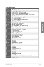
... started SCSI Reset SCSI Detect SCSI Enable Setup Verifying Password Start of Setup Reserved for ASL (see ASL Status Codes section below) Setup Input Wait ASUS P8P67 Deluxe 2-23
... started SCSI Reset SCSI Detect SCSI Enable Setup Verifying Password Start of Setup Reserved for ASL (see ASL Status Codes section below) Setup Input Wait ASUS P8P67 Deluxe 2-23
User Manual
Page 43
.... If you installed Serial ATA hard disk drives, you are set to create a Serial ATA RAID set using Windows® XP SP3 or later versions. ASUS P8P67 Deluxe 2-25 Refer to section 3.5.4 SATA Configuration for details. • You must install Windows® XP Service Pack 3 or later versions before using NCQ, set the...
.... If you installed Serial ATA hard disk drives, you are set to create a Serial ATA RAID set using Windows® XP SP3 or later versions. ASUS P8P67 Deluxe 2-25 Refer to section 3.5.4 SATA Configuration for details. • You must install Windows® XP Service Pack 3 or later versions before using NCQ, set the...
User Manual
Page 45
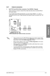
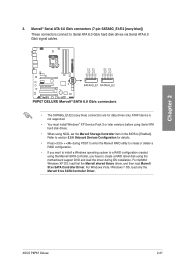
...; Press + during OS installation. For 32/64bit Windows XP OS, load first the Marvell shared library driver, and then load Marvell 91xx SATA Controller Driver. ASUS P8P67 Deluxe 2-27 For Windows Vista / Windows 7 OS, load only the Marvell 91xx SATA Controller Driver. Chapter 2 3. Marvell® Serial ATA 6.0 Gb/s connectors (7-pin SATA6G_E1/E2 [navy...
...; Press + during OS installation. For 32/64bit Windows XP OS, load first the Marvell shared library driver, and then load Marvell 91xx SATA Controller Driver. ASUS P8P67 Deluxe 2-27 For Windows Vista / Windows 7 OS, load only the Marvell 91xx SATA Controller Driver. Chapter 2 3. Marvell® Serial ATA 6.0 Gb/s connectors (7-pin SATA6G_E1/E2 [navy...

User Manual
Page 47
Doing so will damage the motherboard! 6. ASUS P8P67 Deluxe 2-29 The IEEE 1394 bracket is purchased separately. Digital audio connector (4-1 pin SPDIF_OUT) This connector is for an additional Sony/Philips Digital Interface (S/PDIF) port(s). ...
Doing so will damage the motherboard! 6. ASUS P8P67 Deluxe 2-29 The IEEE 1394 bracket is purchased separately. Digital audio connector (4-1 pin SPDIF_OUT) This connector is for an additional Sony/Philips Digital Interface (S/PDIF) port(s). ...

User Manual
Page 49
... either HD Audio or legacy AC`97 audio standard. Front panel audio connector (10-1 pin AAFP) This connector is set the item to [HD]. 10. ASUS P8P67 Deluxe 2-31 Find the proper orientation and push down firmly until the connectors completely fit. ATX power connectors (24-pin EATXPWR; 8-pin EATX12V) These connectors are...
... either HD Audio or legacy AC`97 audio standard. Front panel audio connector (10-1 pin AAFP) This connector is set the item to [HD]. 10. ASUS P8P67 Deluxe 2-31 Find the proper orientation and push down firmly until the connectors completely fit. ATX power connectors (24-pin EATXPWR; 8-pin EATX12V) These connectors are...

User Manual
Page 51
Connect the chassis power LED cable to hear system beeps and warnings. • ATX power button/soft-off the system power. ASUS P8P67 Deluxe 2-33 11. The speaker allows you turn on the system power, and blinks when the system is in sleep or soft-off mode depending on ...
Connect the chassis power LED cable to hear system beeps and warnings. • ATX power button/soft-off the system power. ASUS P8P67 Deluxe 2-33 11. The speaker allows you turn on the system power, and blinks when the system is in sleep or soft-off mode depending on ...

User Manual
Page 53
DO NOT install a LGA1156 CPU on the LGA1155 socket. 1 A B 2 3 ASUS P8P67 Deluxe 2-35 Chapter 2 2.3.2 CPU installation The LGA1156 CPU is incompatible with the LGA1155 socket.
DO NOT install a LGA1156 CPU on the LGA1155 socket. 1 A B 2 3 ASUS P8P67 Deluxe 2-35 Chapter 2 2.3.2 CPU installation The LGA1156 CPU is incompatible with the LGA1155 socket.

User Manual
Page 55
Chapter 2 2.3.3 CPU heatsink and fan assembly installation Apply the Thermal Interface Material to the CPU heatsink and CPU before you install the heatsink and fan if necessary. To install the CPU heatsink and fan assembly 1 A B 2 B A 3 4 ASUS P8P67 Deluxe 2-37
Chapter 2 2.3.3 CPU heatsink and fan assembly installation Apply the Thermal Interface Material to the CPU heatsink and CPU before you install the heatsink and fan if necessary. To install the CPU heatsink and fan assembly 1 A B 2 B A 3 4 ASUS P8P67 Deluxe 2-37

User Manual
Page 57
2.3.4 1 DIMM installation 2 Chapter 2 3 To remove a DIMM B A ASUS P8P67 Deluxe 2-39
2.3.4 1 DIMM installation 2 Chapter 2 3 To remove a DIMM B A ASUS P8P67 Deluxe 2-39


