P8H77-M LE User's Manual
Page 3
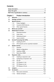
Contents Safety information vi About this guide vi P8H77-M LE specifications summary viii Chapter 1: Product introduction 1.1 Welcome 1-1 1.2 Package contents 1-1 1.3 Special features 1-1 1.3.1 Product highlights 1-1 1.3.2 Innovative ASUS features 1-3 1.3.3 Other special features 1-5 1.4 Before you proceed 1-6 1.5 Motherboard overview 1-7 1.5.1 Placement direction 1-7 1.5.2 Screw holes 1-7 1.5.3 Motherboard... 1.8.5 PCI Express x4 slot 1-20 1.8.6 PCI Express x16 slot 1-21 1.9 Jumpers 1-21 1.10 Connectors 1-22 1.10.1 Rear panel connectors 1-22 1.10.2 Internal connectors 1-24 iii
Contents Safety information vi About this guide vi P8H77-M LE specifications summary viii Chapter 1: Product introduction 1.1 Welcome 1-1 1.2 Package contents 1-1 1.3 Special features 1-1 1.3.1 Product highlights 1-1 1.3.2 Innovative ASUS features 1-3 1.3.3 Other special features 1-5 1.4 Before you proceed 1-6 1.5 Motherboard overview 1-7 1.5.1 Placement direction 1-7 1.5.2 Screw holes 1-7 1.5.3 Motherboard... 1.8.5 PCI Express x4 slot 1-20 1.8.6 PCI Express x16 slot 1-21 1.9 Jumpers 1-21 1.10 Connectors 1-22 1.10.1 Rear panel connectors 1-22 1.10.2 Internal connectors 1-24 iii
P8H77-M LE User's Manual
Page 9
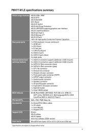
... 1 x 8-pin EATX 12V power connector 1 x MemOK! button 1 x Clear CMOS jumper 64 Mb Flash ROM, UEFI BIOS, PnP, DMI v2.0, WfM 2.0, ACPI v2.0a, SM BIOS v2.5, Multi-language BIOS, ASUS CrashFree BIOS 3, ASUS EZ Flash 2 WOL, PXE, PME Wake Up 2 x Serial ATA 6.0Gb/s cables...shield 1 x User Manual 1 x Support DVD Drivers ASUS utilities ASUS Update Anti-virus software (OEM version) MicroATX form factor: 9.6 in x 8.2 in (24.4 cm x 20.8 cm) * Specifications are subject to change without notice. ix P8H77-M LE specifications summary ASUS unique features Rear panel ports Internal connectors/ switches/ ...
... 1 x 8-pin EATX 12V power connector 1 x MemOK! button 1 x Clear CMOS jumper 64 Mb Flash ROM, UEFI BIOS, PnP, DMI v2.0, WfM 2.0, ACPI v2.0a, SM BIOS v2.5, Multi-language BIOS, ASUS CrashFree BIOS 3, ASUS EZ Flash 2 WOL, PXE, PME Wake Up 2 x Serial ATA 6.0Gb/s cables...shield 1 x User Manual 1 x Support DVD Drivers ASUS utilities ASUS Update Anti-virus software (OEM version) MicroATX form factor: 9.6 in x 8.2 in (24.4 cm x 20.8 cm) * Specifications are subject to change without notice. ix P8H77-M LE specifications summary ASUS unique features Rear panel ports Internal connectors/ switches/ ...
P8H77-M LE User's Manual
Page 18
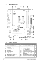
... USB56, 1-28 USB78, USB910) 1-29 16. DRAM_LED 2 24.4cm(9.6in) LAN_USB12 AUDIO Super I/O RTL 8111F CHA_FAN Lithium Cell CMOS Power PCIEX16 P8H77-M LE PCIEX1_1 ASM 1083 PCI1 Intel® H77 7 8 9 CLRTC CHASSIS SATA3G_2 SATA3G_1 64Mb BIOS SB_PWR SATA3G_4 SATA3G_3 10 11 10 USB3_34 ALC 887 AAFP PCIEX4_1... SPDIF_OUT USB910 USB78 SPEAKER USB56 F_PANEL SATA6G_2 SATA6G_1 12 17 16 15 14 13 1.5.4 Layout contents Connectors/Jumpers/Slots/LED 1. DDR3 DIMM slots 5. USB 3.0 connector (20-1 pin USB3_34) 8. Chassis intrusion connector (4-1 pin CHASSIS) Page Connectors...
... USB56, 1-28 USB78, USB910) 1-29 16. DRAM_LED 2 24.4cm(9.6in) LAN_USB12 AUDIO Super I/O RTL 8111F CHA_FAN Lithium Cell CMOS Power PCIEX16 P8H77-M LE PCIEX1_1 ASM 1083 PCI1 Intel® H77 7 8 9 CLRTC CHASSIS SATA3G_2 SATA3G_1 64Mb BIOS SB_PWR SATA3G_4 SATA3G_3 10 11 10 USB3_34 ALC 887 AAFP PCIEX4_1... SPDIF_OUT USB910 USB78 SPEAKER USB56 F_PANEL SATA6G_2 SATA6G_1 12 17 16 15 14 13 1.5.4 Layout contents Connectors/Jumpers/Slots/LED 1. DDR3 DIMM slots 5. USB 3.0 connector (20-1 pin USB3_34) 8. Chassis intrusion connector (4-1 pin CHASSIS) Page Connectors...
P8H77-M LE User's Manual
Page 31
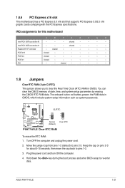
... - PCIE x1 shared - - - - - - - PCI - - The onboard button cell battery powers the RAM data in CMOS. ASUS P8H77-M LE 1-21 IRQ assignments for about 5-10 seconds, then move the cap back to clear the Real Time Clock (RTC) RAM in CMOS, which...cards complying with the PCI Express specifications. PCIE x4 shared - - - - - - - shared - - - - - 1.9 Jumpers Clear RTC RAM (3-pin CLRTC) This jumper allows you to pins 1-2. 3. Move the jumper cap from pins 1-2 (default) to re-enter data. Intel PCH SATA controller #1 - - - Plug the power cord and ...
... - PCIE x1 shared - - - - - - - PCI - - The onboard button cell battery powers the RAM data in CMOS. ASUS P8H77-M LE 1-21 IRQ assignments for about 5-10 seconds, then move the cap back to clear the Real Time Clock (RTC) RAM in CMOS, which...cards complying with the PCI Express specifications. PCIE x4 shared - - - - - - - shared - - - - - 1.9 Jumpers Clear RTC RAM (3-pin CLRTC) This jumper allows you to pins 1-2. 3. Move the jumper cap from pins 1-2 (default) to re-enter data. Intel PCH SATA controller #1 - - - Plug the power cord and ...
P8H77-M LE User's Manual
Page 32
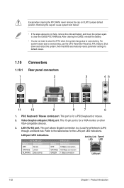
...or other VGA-compatible devices. 3. After clearing the CMOS, reinstall the battery. • You do not help, remove the onboard battery and move the jumper again to overclocking. This port is for a PS/2 keyboard or mouse. 2. PS/2 Keyboard / Mouse combo port. This port allows Gigabit connection to overclocking..., use the CPU Parameter Recall (C.P.R.) feature. Except when clearing the RTC RAM, never remove the cap on CLRTC jumper default position. For system failure due to a Local Area Network (LAN) through a network hub. LAN (RJ-45) port.
...or other VGA-compatible devices. 3. After clearing the CMOS, reinstall the battery. • You do not help, remove the onboard battery and move the jumper again to overclocking. This port is for a PS/2 keyboard or mouse. 2. PS/2 Keyboard / Mouse combo port. This port allows Gigabit connection to overclocking..., use the CPU Parameter Recall (C.P.R.) feature. Except when clearing the RTC RAM, never remove the cap on CLRTC jumper default position. For system failure due to a Local Area Network (LAN) through a network hub. LAN (RJ-45) port.
P8H77-M LE User's Manual
Page 36
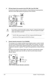
... place jumper caps on the motherboard, ensuring that the black wire of each cable matches the ground pin of maximum 2A (24 W) fan power. • Only the 4-pin CPU fan supports the ASUS Q-Fan 2 feature. 5. The signal is for a chassis-mounted intrusion detection sensor or switch. P8H77-M LE CHASSIS GND Chassis Signal +5VSB_MB P8H77-M LE Chassis...
... place jumper caps on the motherboard, ensuring that the black wire of each cable matches the ground pin of maximum 2A (24 W) fan power. • Only the 4-pin CPU fan supports the ASUS Q-Fan 2 feature. 5. The signal is for a chassis-mounted intrusion detection sensor or switch. P8H77-M LE CHASSIS GND Chassis Signal +5VSB_MB P8H77-M LE Chassis...
P8H77-M LE User's Manual
Page 48
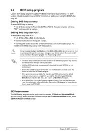
...If the system becomes unstable after changing any BIOS setting, try to clear the CMOS and reset the motherboard to your screen. • Visit the ASUS website at startup: • Press during the Power-On Self Test (POST). Select the Load Optimized Defaults item under two modes: EZ Mode and .... BIOS menu screen The BIOS setup program can be used under the Exit menu. You can cause damage to the default value. See section 1.9 Jumpers for this option only if you in the EZ Mode/Advanced Mode screen. 2-6 Chapter 2: BIOS information Entering BIOS Setup after POST To enter BIOS ...
...If the system becomes unstable after changing any BIOS setting, try to clear the CMOS and reset the motherboard to your screen. • Visit the ASUS website at startup: • Press during the Power-On Self Test (POST). Select the Load Optimized Defaults item under two modes: EZ Mode and .... BIOS menu screen The BIOS setup program can be used under the Exit menu. You can cause damage to the default value. See section 1.9 Jumpers for this option only if you in the EZ Mode/Advanced Mode screen. 2-6 Chapter 2: BIOS information Entering BIOS Setup after POST To enter BIOS ...
P8H77-M LE User's Manual
Page 52
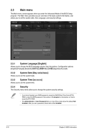
... Time Clock (RTC) RAM to erase the RTC RAM. • The Administrator or User Password items on top of the BIOS Setup program. See section 1.9 Jumpers for information on how to clear the BIOS password. 2.3 Main menu The Main menu screen appears when you enter the Advanced Mode of the screen...
... Time Clock (RTC) RAM to erase the RTC RAM. • The Administrator or User Password items on top of the BIOS Setup program. See section 1.9 Jumpers for information on how to clear the BIOS password. 2.3 Main menu The Main menu screen appears when you enter the Advanced Mode of the screen...

