User Manual
Page 13
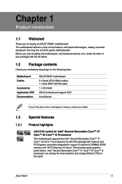
...you for the following items. Motherboard Cables Accessories Application DVD Documentation ASUS P8H67 motherboard 2 x Serial ATA 6.0Gb/s cables 1 x Ultra DMA 133/100 cable 1 x I/O shield ASUS motherboard support DVD User Manual If any of ASUS quality motherboards! Chapter 1 Product introduction 1.1 Welcome! Thank you ... Core™ i3 processors are among the most powerful and energy efficient CPUs in your motherboard package for buying an ASUS® P8H67 motherboard! The motherboard delivers a host of new features and latest technologies, making it , check the items in the...
...you for the following items. Motherboard Cables Accessories Application DVD Documentation ASUS P8H67 motherboard 2 x Serial ATA 6.0Gb/s cables 1 x Ultra DMA 133/100 cable 1 x I/O shield ASUS motherboard support DVD User Manual If any of ASUS quality motherboards! Chapter 1 Product introduction 1.1 Welcome! Thank you ... Core™ i3 processors are among the most powerful and energy efficient CPUs in your motherboard package for buying an ASUS® P8H67 motherboard! The motherboard delivers a host of new features and latest technologies, making it , check the items in the...
User Manual
Page 15
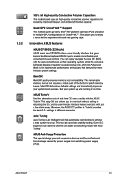
... for durability, improved lifespan, and enhanced thermal capacity. Even O.C. beginners can easily navigate the new EFI BIOS with the ASUS TurboV. determines failsafe settings and dramatically improves your system up . 1.3.2 100% All High-quality Conductive Polymer Capacitors This motherboard... tool that goes beyond traditional keyboard BIOS input to enjoy a never before-experienced brand new gaming style. MemOK! ASUS P8H67 1-3 ASUS Anti-Surge Protection This special design prevents expensive devices and the motherboard from damage caused by power surges from switching power...
... for durability, improved lifespan, and enhanced thermal capacity. Even O.C. beginners can easily navigate the new EFI BIOS with the ASUS TurboV. determines failsafe settings and dramatically improves your system up . 1.3.2 100% All High-quality Conductive Polymer Capacitors This motherboard... tool that goes beyond traditional keyboard BIOS input to enjoy a never before-experienced brand new gaming style. MemOK! ASUS P8H67 1-3 ASUS Anti-Surge Protection This special design prevents expensive devices and the motherboard from damage caused by power surges from switching power...
User Manual
Page 17
...-efficient products through product design and innovation to reduce carbon footprint of the product and thus mitigate environmental impacts. eliminates the need to overclocking failure. ASUS P8H67 1-5 feature automatically restores the CPU default settings when the system hangs due to open the system chassis and clear the RTC data. Simply shut down...
...-efficient products through product design and innovation to reduce carbon footprint of the product and thus mitigate environmental impacts. eliminates the need to overclocking failure. ASUS P8H67 1-5 feature automatically restores the CPU default settings when the system hangs due to open the system chassis and clear the RTC data. Simply shut down...
User Manual
Page 19
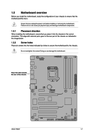
... installing the motherboard, ensure that the motherboard fits into the holes indicated by circles to secure the motherboard to the rear part of the chassis P8H67 ASUS P8H67 1-7 1.5 Motherboard overview Before you unplug the power cord before installing or removing the motherboard.
... installing the motherboard, ensure that the motherboard fits into the holes indicated by circles to secure the motherboard to the rear part of the chassis P8H67 ASUS P8H67 1-7 1.5 Motherboard overview Before you unplug the power cord before installing or removing the motherboard.
User Manual
Page 21
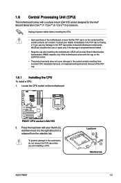
...Core™ i5 / Core™ i3 processors. To prevent damage to the right (B) until it is on the motherboard. Load lever A B Retention tab ASUS P8H67 1-9 ASUS will shoulder the cost of the PnP cap. 1.6.1 Installing the CPU To install a CPU: 1. Unplug all power cables before installing the CPU. • ...incorrect CPU installation/removal, or misplacement/loss/incorrect removal of repair only if the damage is missing, or if you are not bent. P8H67 P8H67 CPU socket LGA1155 2. Contact your thumb (A), and then move it to the socket pins, do not remove the PnP cap unless ...
...Core™ i5 / Core™ i3 processors. To prevent damage to the right (B) until it is on the motherboard. Load lever A B Retention tab ASUS P8H67 1-9 ASUS will shoulder the cost of the PnP cap. 1.6.1 Installing the CPU To install a CPU: 1. Unplug all power cables before installing the CPU. • ...incorrect CPU installation/removal, or misplacement/loss/incorrect removal of repair only if the damage is missing, or if you are not bent. P8H67 P8H67 CPU socket LGA1155 2. Contact your thumb (A), and then move it to the socket pins, do not remove the PnP cap unless ...
User Manual
Page 23
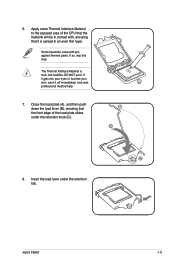
... contact with preapplied thermal paste. Insert the load lever under the retention knob (C). If it gets into your eyes or touches your skin, wash it . ASUS P8H67 1-11 B A C 8. If so, skip this step. Close the load plate (A), and then push down the load lever (B), ensuring that the front edge of the CPU...
... contact with preapplied thermal paste. Insert the load lever under the retention knob (C). If it gets into your eyes or touches your skin, wash it . ASUS P8H67 1-11 B A C 8. If so, skip this step. Close the load plate (A), and then push down the load lever (B), ensuring that the front edge of the CPU...
User Manual
Page 25
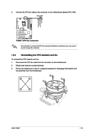
Pull up two fasteners at a time in a diagonal sequence to the connector on the motherboard. 2. 3. A B A B B A B A ASUS P8H67 1-13 Disconnect the CPU fan cable from the motherboard. CPU_FAN CPU FAN PWM CPU FAN IN CPU FAN PWR GND P8H67 P8H67 CPU fan connector Do not forget to plug this connector. 1.6.3 Uninstalling the CPU heatsink and fan...
Pull up two fasteners at a time in a diagonal sequence to the connector on the motherboard. 2. 3. A B A B B A B A ASUS P8H67 1-13 Disconnect the CPU fan cable from the motherboard. CPU_FAN CPU FAN PWM CPU FAN IN CPU FAN PWR GND P8H67 P8H67 CPU fan connector Do not forget to plug this connector. 1.6.3 Uninstalling the CPU heatsink and fan...
User Manual
Page 27
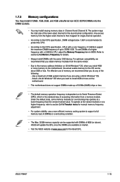
... for the OS can be about 3GB or less. The system maps the total size of 8GB (or above). ASUS P8H67 1-15 Any excess memory from the higher-sized channel is recommended to protect the CPU. • According to Intel CPU specification, CPUs with a 2.66GHz CPU, ... is then mapped for details. • Always install DIMMs with DIMMs of the lower-sized channel for overclocking may install varying memory sizes in BIOS. ASUS will update the QVL once the DIMMs are using a 32-bit Windows® OS. - For effective use a more memory on 32-bit Windows® OS...
... for the OS can be about 3GB or less. The system maps the total size of 8GB (or above). ASUS P8H67 1-15 Any excess memory from the higher-sized channel is recommended to protect the CPU. • According to Intel CPU specification, CPUs with a 2.66GHz CPU, ... is then mapped for details. • Always install DIMMs with DIMMs of the lower-sized channel for overclocking may install varying memory sizes in BIOS. ASUS will update the QVL once the DIMMs are using a 32-bit Windows® OS. - For effective use a more memory on 32-bit Windows® OS...
User Manual
Page 31
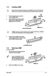
... clips snap back in only one direction. Remove the DIMM from the socket. Simultaneously press the retaining clips outward to unlock a DIMM socket. 2. DIMM notch ASUS P8H67 1-19 Press the retaining clips outward to unlock the DIMM. 2 Support the DIMM lightly with extra force. 1 2. Locked Retaining Clip 1.7.4 Removing a DIMM To remove a DIMM...
... clips snap back in only one direction. Remove the DIMM from the socket. Simultaneously press the retaining clips outward to unlock a DIMM socket. 2. DIMM notch ASUS P8H67 1-19 Press the retaining clips outward to unlock the DIMM. 2 Support the DIMM lightly with extra force. 1 2. Locked Retaining Clip 1.7.4 Removing a DIMM To remove a DIMM...
User Manual
Page 33
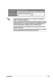
...) x16 PCIe x16_2 N/A x4 • In single VGA card mode, use the PCIe x1 slot when you provide sufficient power when running CrossFireX™ mode. ASUS P8H67 1-21 To disable the PCIe x1 slot, refer to the Onboard Devices Configuration section in the BIOS for details. • We recommend that you install...
...) x16 PCIe x16_2 N/A x4 • In single VGA card mode, use the PCIe x1 slot when you provide sufficient power when running CrossFireX™ mode. ASUS P8H67 1-21 To disable the PCIe x1 slot, refer to the Onboard Devices Configuration section in the BIOS for details. • We recommend that you install...

User Manual
Page 35
... Gigabit connection to the table below for the LAN port LED indicators. Refer to the audio configuration table on the next page for a PS/2 mouse. 2. ASUS P8H67 1-23
... Gigabit connection to the table below for the LAN port LED indicators. Refer to the audio configuration table on the next page for a PS/2 mouse. 2. ASUS P8H67 1-23
User Manual
Page 37
... Black Black Gray Black or gray • Pin 20 on the IDE connector is removed to PIN 1. ASUS P8H67 1-25 If any device jumper is for Ultra DMA 133/100 IDE devices. P8H67 PRI_EIDE PIN1 P8H67 IDE connector NOTE:Orient the red markings on the IDE ribbon cable to match the covered hole on...
... Black Black Gray Black or gray • Pin 20 on the IDE connector is removed to PIN 1. ASUS P8H67 1-25 If any device jumper is for Ultra DMA 133/100 IDE devices. P8H67 PRI_EIDE PIN1 P8H67 IDE connector NOTE:Orient the red markings on the IDE ribbon cable to match the covered hole on...
User Manual
Page 39
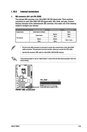
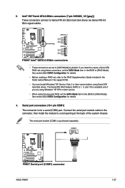
...connectors, set the SATA Mode item in the BIOS to [AHCI Mode]. P8H67 SATA6G_2 GND RSATA_TXP2 RSATA_TXN2 GND RSATA_RXP2 RSATA_RXN2 GND SATA6G_1 GND RSATA_TXP1 RSATA_TXN1 GND RSATA_RXP1 RSATA_RXN1 GND P8H67 Intel® SATA 6.0Gb/s connectors • These connectors are using Windows&#...then install the module to Serial ATA 6.0 Gb/s hard disk drives via Serial ATA 6.0 Gb/s signal cables. COM1 PIN 1 P8H67 P8H67 Serial port (COM1) connector ASUS P8H67 1-27 Serial port connectors (10-1 pin COM1) The connector is purchased separately. 3. Intel® H67 Serial ATA 6.0Gb/s ...
...connectors, set the SATA Mode item in the BIOS to [AHCI Mode]. P8H67 SATA6G_2 GND RSATA_TXP2 RSATA_TXN2 GND RSATA_RXP2 RSATA_RXN2 GND SATA6G_1 GND RSATA_TXP1 RSATA_TXN1 GND RSATA_RXP1 RSATA_RXN1 GND P8H67 Intel® SATA 6.0Gb/s connectors • These connectors are using Windows&#...then install the module to Serial ATA 6.0 Gb/s hard disk drives via Serial ATA 6.0 Gb/s signal cables. COM1 PIN 1 P8H67 P8H67 Serial port (COM1) connector ASUS P8H67 1-27 Serial port connectors (10-1 pin COM1) The connector is purchased separately. 3. Intel® H67 Serial ATA 6.0Gb/s ...
User Manual
Page 41
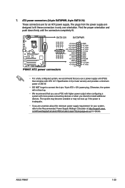
...supply requirement for your system, refer to install additional devices. com/PowerSupplyCalculator/PSCalculator.aspx?SLanguage=en-us for an ATX power supply. ASUS P8H67 1-29 The system may become unstable or may not boot up . • We recommend that complies with more power-consuming devices... or when you intend to the Recommended Power Supply Wattage Calculator at http://support.asus. The plugs from the power supply are for details. Find the proper orientation and push down firmly until the connectors completely fit....
...supply requirement for your system, refer to install additional devices. com/PowerSupplyCalculator/PSCalculator.aspx?SLanguage=en-us for an ATX power supply. ASUS P8H67 1-29 The system may become unstable or may not boot up . • We recommend that complies with more power-consuming devices... or when you intend to the Recommended Power Supply Wattage Calculator at http://support.asus. The plugs from the power supply are for details. Find the proper orientation and push down firmly until the connectors completely fit....
User Manual
Page 43
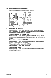
ASUS P8H67 1-31 Connect the chassis power LED cable to this connector. The speaker allows you turn on the system power, and blinks when the system is ...) This 2-pin connector is for the chassis-mounted reset button for the system power LED. PWR Ground Reset Ground PANEL PIN 1 P8H67 IDE_LED PWRSW RESET * Requires an ATX power supply P8H67 System panel connector • System power LED (2-pin PLED) This 2-pin connector is for the HDD Activity LED. The IDE LED...
ASUS P8H67 1-31 Connect the chassis power LED cable to this connector. The speaker allows you turn on the system power, and blinks when the system is ...) This 2-pin connector is for the chassis-mounted reset button for the system power LED. PWR Ground Reset Ground PANEL PIN 1 P8H67 IDE_LED PWRSW RESET * Requires an ATX power supply P8H67 System panel connector • System power LED (2-pin PLED) This 2-pin connector is for the HDD Activity LED. The IDE LED...
User Manual
Page 45
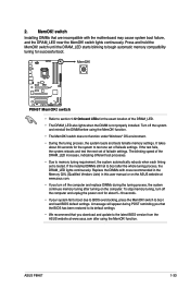
...tuning, turn off the system and reinstall the DIMM before using the MemOK! function. Press and hold the MemOK! P8H67 P8H67 MemOK! switch does not function under Windows® OS environment. • During the tuning process, the system loads ... DRAM_LED starts blinking to begin automatic memory compatibility tuning for the system to boot after turning on the ASUS website at www.asus.com after using the MemOK! The blinking speed of failsafe settings. It takes about 5-10 seconds. ... computer and unplug the power cord for the exact location of failsafe settings. ASUS P8H67 1-33
...tuning, turn off the system and reinstall the DIMM before using the MemOK! function. Press and hold the MemOK! P8H67 P8H67 MemOK! switch does not function under Windows® OS environment. • During the tuning process, the system loads ... DRAM_LED starts blinking to begin automatic memory compatibility tuning for the system to boot after turning on the ASUS website at www.asus.com after using the MemOK! The blinking speed of failsafe settings. It takes about 5-10 seconds. ... computer and unplug the power cord for the exact location of failsafe settings. ASUS P8H67 1-33
User Manual
Page 47
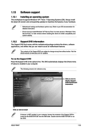
... drivers, software applications, and utilities that you can install to your hardware. • Motherboard settings and hardware options vary. Visit the ASUS website at any time without notice. Click an icon to display Support DVD/motherboard information Click an item to locate the file ASSETUP.EXE...® XP / Vista / 7 Operating Systems (OS). The contents of the Support DVD to install If Autorun is for reference only. ASUS P8H67 1-35 Double-click the ASSETUP.EXE to run the Support DVD Place the Support DVD to maximize the features of your OS documentation for detailed...
... drivers, software applications, and utilities that you can install to your hardware. • Motherboard settings and hardware options vary. Visit the ASUS website at any time without notice. Click an icon to display Support DVD/motherboard information Click an item to locate the file ASSETUP.EXE...® XP / Vista / 7 Operating Systems (OS). The contents of the Support DVD to install If Autorun is for reference only. ASUS P8H67 1-35 Double-click the ASSETUP.EXE to run the Support DVD Place the Support DVD to maximize the features of your OS documentation for detailed...

User Manual
Page 50
.../27/10 10:23p 4194304 Exit DATE: 10/13/2010 P8H67.ROM File Info MODEL: Help Info VER: DATE [Enter] Select or Load [Tab] Switch [Up/Down/PageUp/PageDown/Home/End] Move [Esc] Exit 2-2 ASUS P8H67 The ASUS Update utility is capable of the BIOS setup program. Before... you to avail all its features. Follow the onscreen instructions to complete the updating process. 2.1.2 ASUS EZ Flash 2 The ASUS EZ Flash 2 feature allows you start using this utility...
.../27/10 10:23p 4194304 Exit DATE: 10/13/2010 P8H67.ROM File Info MODEL: Help Info VER: DATE [Enter] Select or Load [Tab] Switch [Up/Down/PageUp/PageDown/Home/End] Move [Esc] Exit 2-2 ASUS P8H67 The ASUS Update utility is capable of the BIOS setup program. Before... you to avail all its features. Follow the onscreen instructions to complete the updating process. 2.1.2 ASUS EZ Flash 2 The ASUS EZ Flash 2 feature allows you start using this utility...
User Manual
Page 52
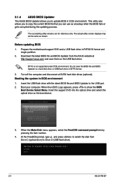
... (USB flash drive). When the Make Disk menu appears, select the FreeDOS command prompt item by pressing the item number. 4. C:\>d: D:\> 2-4 ASUS P8H67 Booting the system in FAT32/16 format and single partition. 2. The succeeding utility screens are for reference only. Prepare the motherboard support DVD and ... drive in DOS environment 1. Do not save them on the USB flash drive. NTFS is not supported under DOS environment. When the ASUS Logo appears, press to a hard disk drive or USB flash drive in DOS environment. Please select boot device: SATA: XXXXXXXXXXXXXXXX USB ...
... (USB flash drive). When the Make Disk menu appears, select the FreeDOS command prompt item by pressing the item number. 4. C:\>d: D:\> 2-4 ASUS P8H67 Booting the system in FAT32/16 format and single partition. 2. The succeeding utility screens are for reference only. Prepare the motherboard support DVD and ... drive in DOS environment 1. Do not save them on the USB flash drive. NTFS is not supported under DOS environment. When the ASUS Logo appears, press to a hard disk drive or USB flash drive in DOS environment. Please select boot device: SATA: XXXXXXXXXXXXXXXX USB ...
User Manual
Page 54
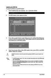
.../pc /g 2. Yes No 4. Refer to section 2.9 Exit menu for DOS V1.07 Current ROM BOARD: P8H67 VER: 0217 DATE: 10/13/2010 Update ROM BOARD: Unknown VER: Unknown DATE: Unknown PATH: A:\ A: P8H67.ROM 4194304 2010-09-20 17:30:48 Note [Enter] Select or Load [Up/Down/Home/End] Move...load the BIOS default settings to ensure system compatibility and stability. BIOS Updater checks the selected BIOS file and prompts you have disconnected them. 2-6 ASUS P8H67 Select Yes and press . When BIOS update is done, press to select the BIOS file and press . Restart your computer. Press to ...
.../pc /g 2. Yes No 4. Refer to section 2.9 Exit menu for DOS V1.07 Current ROM BOARD: P8H67 VER: 0217 DATE: 10/13/2010 Update ROM BOARD: Unknown VER: Unknown DATE: Unknown PATH: A:\ A: P8H67.ROM 4194304 2010-09-20 17:30:48 Note [Enter] Select or Load [Up/Down/Home/End] Move...load the BIOS default settings to ensure system compatibility and stability. BIOS Updater checks the selected BIOS file and prompts you have disconnected them. 2-6 ASUS P8H67 Select Yes and press . When BIOS update is done, press to select the BIOS file and press . Restart your computer. Press to ...


