
User Manual
Page 13
...list below. 1.2 Package contents Check your retailer. 1.3 1.3.1 Special features Product highlights LGA1155 socket for buying an ASUS® P8H67-V motherboard! This provides great graphics performance. The motherboard delivers a host of new features and latest technologies, ...items. Motherboard Cables Accessories Application DVD Documentation ASUS P8H67-V motherboard 2 x Serial ATA 6.0Gb/s cables 1 x Ultra DMA 133/100 cable 1 x I/O shield ASUS motherboard support DVD User Manual If any of ASUS quality motherboards! ASUS P8H67-V 1-1 Thank you start installing the motherboard...
...list below. 1.2 Package contents Check your retailer. 1.3 1.3.1 Special features Product highlights LGA1155 socket for buying an ASUS® P8H67-V motherboard! This provides great graphics performance. The motherboard delivers a host of new features and latest technologies, ...items. Motherboard Cables Accessories Application DVD Documentation ASUS P8H67-V motherboard 2 x Serial ATA 6.0Gb/s cables 1 x Ultra DMA 133/100 cable 1 x I/O shield ASUS motherboard support DVD User Manual If any of ASUS quality motherboards! ASUS P8H67-V 1-1 Thank you start installing the motherboard...

User Manual
Page 15
...up and running in no time. This allows you to enjoy a never before-experienced brand new gaming style. Innovative ASUS features ASUS EFI BIOS (EZ Mode) ASUS brand new EFI BIOS offers a user-friendly interface that goes beyond traditional keyboard BIOS input to patch memory issues. MemOK... EZ Mode displays frequently-accessed setup info, while the Advanced Mode is enhanced with the ASUS TurboV. MemOK! Get your system boot success. settings in TurboV provides the best O.C. ASUS P8H67-V 1-3 1.3.2 Gigabit LAN solution The onboard LAN controller is an intelligent tool that demand far...
...up and running in no time. This allows you to enjoy a never before-experienced brand new gaming style. Innovative ASUS features ASUS EFI BIOS (EZ Mode) ASUS brand new EFI BIOS offers a user-friendly interface that goes beyond traditional keyboard BIOS input to patch memory issues. MemOK... EZ Mode displays frequently-accessed setup info, while the Advanced Mode is enhanced with the ASUS TurboV. MemOK! Get your system boot success. settings in TurboV provides the best O.C. ASUS P8H67-V 1-3 1.3.2 Gigabit LAN solution The onboard LAN controller is an intelligent tool that demand far...

User Manual
Page 17
... need to the motherboard, peripherals, or components. C.P.R. (CPU Parameter Recall) The BIOS C.P.R. This is in line with ASUS vision of creating environment-friendly and energy-efficient products through product design and innovation to reduce carbon footprint of the product and...power cord from the power supply. Failure to do so may cause severe damage to open the system chassis and clear the RTC data. ASUS P8H67-V 1-5 Simply shut down and reboot the system, and the BIOS automatically restores the CPU parameters to overclocking failure. C.P.R. feature automatically restores ...
... need to the motherboard, peripherals, or components. C.P.R. (CPU Parameter Recall) The BIOS C.P.R. This is in line with ASUS vision of creating environment-friendly and energy-efficient products through product design and innovation to reduce carbon footprint of the product and...power cord from the power supply. Failure to do so may cause severe damage to open the system chassis and clear the RTC data. ASUS P8H67-V 1-5 Simply shut down and reboot the system, and the BIOS automatically restores the CPU parameters to overclocking failure. C.P.R. feature automatically restores ...

User Manual
Page 21
... from the CPU socket by lifting the tab only. DO NOT force the CPU into the CPU notches. Gold triangle mark Alignment keys CPU notches ASUS P8H67-V 1-9 Load plate 4. 3. Lift the load lever in only one correct orientation. Position the CPU over the socket, ensuring that the gold triangle is completely lifted...
... from the CPU socket by lifting the tab only. DO NOT force the CPU into the CPU notches. Gold triangle mark Alignment keys CPU notches ASUS P8H67-V 1-9 Load plate 4. 3. Lift the load lever in only one correct orientation. Position the CPU over the socket, ensuring that the gold triangle is completely lifted...

User Manual
Page 23
... fan and heatsink assembly. The illustration above is for reference only. Place the heatsink on the motherboard. If you install the heatsink and fan assembly. ASUS P8H67-V 1-11
... fan and heatsink assembly. The illustration above is for reference only. Place the heatsink on the motherboard. If you install the heatsink and fan assembly. ASUS P8H67-V 1-11

User Manual
Page 25
... Modules (DIMM) sockets. The figure illustrates the location of the DDR3 DIMM sockets: DIMM_A1 DIMM_A2 DIMM_B1 DIMM_B2 Channel Sockets P8H67-V Channel A DIMM_A1 and DIMM_A2 Channel B DIMM_B1 and DIMM_B2 P8H67-V 240-pin DDR3 DIMM sockets ASUS P8H67-V 1-13 Carefully remove the heatsink and fan assembly from the motherboard. 5. A DDR3 module has the same physical dimensions...
... Modules (DIMM) sockets. The figure illustrates the location of the DDR3 DIMM sockets: DIMM_A1 DIMM_A2 DIMM_B1 DIMM_B2 Channel Sockets P8H67-V Channel A DIMM_A1 and DIMM_A2 Channel B DIMM_B1 and DIMM_B2 P8H67-V 240-pin DDR3 DIMM sockets ASUS P8H67-V 1-13 Carefully remove the heatsink and fan assembly from the motherboard. 5. A DDR3 module has the same physical dimensions...

User Manual
Page 29
... and the black slots as one (1) module inserted into either the blue slots or the black slots as two pairs of dual-channel memory configuration. ASUS P8H67-V 1-17 DDR3-1066MHz capability Vendors Part No. DIMM support A* B* C • •• • •• • •• • •• SS: Single-sided / DS...
... and the black slots as one (1) module inserted into either the blue slots or the black slots as two pairs of dual-channel memory configuration. ASUS P8H67-V 1-17 DDR3-1066MHz capability Vendors Part No. DIMM support A* B* C • •• • •• • •• • •• SS: Single-sided / DS...

User Manual
Page 31
... card After installing the expansion card, configure it and make the necessary hardware settings for the expansion card. Install the software drivers for the card. 2. ASUS P8H67-V 1-19 1.8 Expansion slots In the future, you may cause you physical injury and damage motherboard components. 1.8.1 Installing an expansion card To install an expansion card...
... card After installing the expansion card, configure it and make the necessary hardware settings for the expansion card. Install the software drivers for the card. 2. ASUS P8H67-V 1-19 1.8 Expansion slots In the future, you may cause you physical injury and damage motherboard components. 1.8.1 Installing an expansion card To install an expansion card...

User Manual
Page 33
... CMOS, reinstall the battery. • You do not help, remove the onboard battery and move the cap back to clear the CMOS RTC RAM data. ASUS P8H67-V 1-21 Hold down and reboot the system, then the BIOS automatically resets parameter settings to re-enter data. Shut down the key during the boot...
... CMOS, reinstall the battery. • You do not help, remove the onboard battery and move the cap back to clear the CMOS RTC RAM data. ASUS P8H67-V 1-21 Hold down and reboot the system, then the BIOS automatically resets parameter settings to re-enter data. Shut down the key during the boot...

User Manual
Page 35
... Serial Bus (USB) ports connect to USB 2.0/1.1 devices. This port is for a High-Definition Multimedia Interface (HDMI) connector, and is for your USB 3.0 devices. 13. ASUS P8H67-V 1-23 DVI-D can only be converted to output RGB Signal to any DVI-D compatible device. Rear Speaker Out - 6-channel Line in Front Speaker Out Mic...
... Serial Bus (USB) ports connect to USB 2.0/1.1 devices. This port is for a High-Definition Multimedia Interface (HDMI) connector, and is for your USB 3.0 devices. 13. ASUS P8H67-V 1-23 DVI-D can only be converted to output RGB Signal to any DVI-D compatible device. Rear Speaker Out - 6-channel Line in Front Speaker Out Mic...

User Manual
Page 37
... maximum 2A (24 W) fan power. • Only the CPU_FAN, CHA_FAN1 and CHA_FAN2 connectors support the ASUS Fan Xpert feature. • If you install two VGA cards, we recommend that you plug the rear...the fan cables to the fan connectors. Insufficient air flow inside the system may damage the motherboard components. ASUS P8H67-V 1-25 DO NOT forget to connect the fan cables to the fan connectors on the fan connectors.... CPU_FAN CPU FAN PWM CPU FAN IN CPU FAN PWR GND P8H67-V CHA_FAN2 CPU FAN PWM CPU FAN IN CPU FAN PWR GND CHA_FAN1 PWR_FAN GND CPU FAN ...
... maximum 2A (24 W) fan power. • Only the CPU_FAN, CHA_FAN1 and CHA_FAN2 connectors support the ASUS Fan Xpert feature. • If you install two VGA cards, we recommend that you plug the rear...the fan cables to the fan connectors. Insufficient air flow inside the system may damage the motherboard components. ASUS P8H67-V 1-25 DO NOT forget to connect the fan cables to the fan connectors on the fan connectors.... CPU_FAN CPU FAN PWM CPU FAN IN CPU FAN PWR GND P8H67-V CHA_FAN2 CPU FAN PWM CPU FAN IN CPU FAN PWR GND CHA_FAN1 PWR_FAN GND CPU FAN ...

User Manual
Page 39
...• If you intend to connect the 4-pin / 8-pin ATX +12V power plug. EATX12V EATXPWR +12V DC +12V DC +12V DC +12V DC P8H67-V GND GND GND GND +3 Volts +12 Volts +12 Volts +5V Standby Power OK PIN 1 GND +5 Volts GND +5 Volts GND +3 Volts +3 Volts PIN... a system with ATX 12 V Specification 2.0 (or later version) and provides a minimum power of 350 W. • DO NOT forget to install additional devices. ASUS P8H67-V 1-27 The plugs from the power supply are for details. com/PowerSupplyCalculator/PSCalculator.aspx?SLanguage=en-us for an ATX power supply.
...• If you intend to connect the 4-pin / 8-pin ATX +12V power plug. EATX12V EATXPWR +12V DC +12V DC +12V DC +12V DC P8H67-V GND GND GND GND +3 Volts +12 Volts +12 Volts +5V Standby Power OK PIN 1 GND +5 Volts GND +5 Volts GND +3 Volts +3 Volts PIN... a system with ATX 12 V Specification 2.0 (or later version) and provides a minimum power of 350 W. • DO NOT forget to install additional devices. ASUS P8H67-V 1-27 The plugs from the power supply are for details. com/PowerSupplyCalculator/PSCalculator.aspx?SLanguage=en-us for an ATX power supply.

User Manual
Page 41
... Master Slave Cable connector Black Black Gray Black or gray • Pin 20 on the IDE connector is removed to PIN 1. PRI_EIDE P8H67-V PIN1 P8H67-V IDE connector NOTE:Orient the red markings on the IDE ribbon cable to match the covered hole on each Ultra DMA 133/100 signal...set as "Cable-Select", ensure that all other device jumpers have the same setting. There are three connectors on the Ultra DMA cable connector. ASUS P8H67-V 1-29 Connect the blue connector to the motherboard's IDE connector, then select one of the following modes to configure your devices: Single device ...
... Master Slave Cable connector Black Black Gray Black or gray • Pin 20 on the IDE connector is removed to PIN 1. PRI_EIDE P8H67-V PIN1 P8H67-V IDE connector NOTE:Orient the red markings on the IDE ribbon cable to match the covered hole on each Ultra DMA 133/100 signal...set as "Cable-Select", ensure that all other device jumpers have the same setting. There are three connectors on the Ultra DMA cable connector. ASUS P8H67-V 1-29 Connect the blue connector to the motherboard's IDE connector, then select one of the following modes to configure your devices: Single device ...
User Manual
Page 43
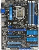
.... A message will appear during the tuning process, the system continues memory tuning after the whole tuning process, the DRAM_LED lights continuously. ASUS P8H67-V 1-31 switch lights continuously. If the test fails, the system reboots and test the next set of failsafe settings. Replace the DIMMs...recommend that are incompatible with ones recommended in the Memory QVL (Qualified Vendors Lists) in this user manual or on the ASUS website at www.asus.com after using the MemOK! This is ideal for successful boot. 1.11 Onboard switches Onboard switches allow you download and ...
.... A message will appear during the tuning process, the system continues memory tuning after the whole tuning process, the DRAM_LED lights continuously. ASUS P8H67-V 1-31 switch lights continuously. If the test fails, the system reboots and test the next set of failsafe settings. Replace the DIMMs...recommend that are incompatible with ones recommended in the Memory QVL (Qualified Vendors Lists) in this user manual or on the ASUS website at www.asus.com after using the MemOK! This is ideal for successful boot. 1.11 Onboard switches Onboard switches allow you download and ...

User Manual
Page 45
... system is a reminder that you should shut down the system and unplug the power cable before removing or plugging in any motherboard component. P8H67-V DRAM LED P8H67-V DRAM LED ASUS P8H67-V 1-33 This is ON, in sleep mode, or in sequence during motherboard booting process. DRAM LED DRAM LED checks the DRAM in soft...
... system is a reminder that you should shut down the system and unplug the power cable before removing or plugging in any motherboard component. P8H67-V DRAM LED P8H67-V DRAM LED ASUS P8H67-V 1-33 This is ON, in sleep mode, or in sequence during motherboard booting process. DRAM LED DRAM LED checks the DRAM in soft...
User Manual
Page 48
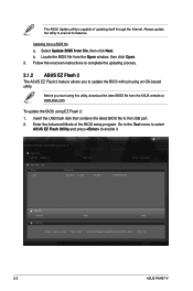
Before you to update the BIOS without using an OS‑based utility. Follow the onscreen instructions to avail all its features. The ASUS Update utility is capable of the BIOS setup program. Insert the USB flash disk that contains the latest BIOS file to enable it. Select Update ... BIOS file from file, then click Next. Locate the BIOS file from a BIOS file a. ASUSTek EZ Flash 2 BIOS ROM Utility V00.74 Flash Info MODEL: P8H67-V File Path: fs0:\ Drive fs0:\ VER: 0211 Folder Info 09/27/10 10:23p 4194304 Exit DATE: 09/20/2010 P8H67V.ROM File Info MODEL...
Before you to update the BIOS without using an OS‑based utility. Follow the onscreen instructions to avail all its features. The ASUS Update utility is capable of the BIOS setup program. Insert the USB flash disk that contains the latest BIOS file to enable it. Select Update ... BIOS file from file, then click Next. Locate the BIOS file from a BIOS file a. ASUSTek EZ Flash 2 BIOS ROM Utility V00.74 Flash Info MODEL: P8H67-V File Path: fs0:\ Drive fs0:\ VER: 0211 Folder Info 09/27/10 10:23p 4194304 Exit DATE: 09/20/2010 P8H67V.ROM File Info MODEL...

User Manual
Page 50
... the optical drive and select the optical drive as a backup when the BIOS fails or gets corrupted during the updating process. C:\>d: D:\> 2-4 ASUS P8H67-V The actual utility screen displays may not be same as shown. Welcome to show the BIOS Boot Device Select Menu. When the Make Disk... menu appears, select the FreeDOS command prompt item by pressing the item number. 4. 2.1.4 ASUS BIOS Updater The ASUS BIOS Updater allows you can use as the boot device. NTFS is not supported under DOS environment. Booting the system in NTFS format...
... the optical drive and select the optical drive as a backup when the BIOS fails or gets corrupted during the updating process. C:\>d: D:\> 2-4 ASUS P8H67-V The actual utility screen displays may not be same as shown. Welcome to show the BIOS Boot Device Select Menu. When the Make Disk... menu appears, select the FreeDOS command prompt item by pressing the item number. 4. 2.1.4 ASUS BIOS Updater The ASUS BIOS Updater allows you can use as the boot device. NTFS is not supported under DOS environment. Booting the system in NTFS format...
User Manual
Page 52
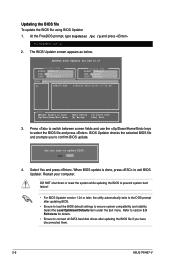
... under the Exit menu. Are you sure to confirm BIOS update. BIOS Updater checks the selected BIOS file and prompts you have disconnected them. 2-6 ASUS P8H67-V D:\>bupdater /pc /g 2. The BIOS Updater screen appears as below. ASUSTek BIOS Updater for details. • Ensure to connect all SATA hard ...failure! • For BIOS Updater version 1.04 or later, the utility automatically exits to section 2.9 Exit menu for DOS V1.07 Current ROM BOARD: P8H67-V VER: 0217 DATE: 09/25/2010 Update ROM BOARD: Unknown VER: Unknown DATE: Unknown PATH: A:\ A: P8H67V.ROM 4194304 2010-09-20 17...
... under the Exit menu. Are you sure to confirm BIOS update. BIOS Updater checks the selected BIOS file and prompts you have disconnected them. 2-6 ASUS P8H67-V D:\>bupdater /pc /g 2. The BIOS Updater screen appears as below. ASUSTek BIOS Updater for details. • Ensure to connect all SATA hard ...failure! • For BIOS Updater version 1.04 or later, the utility automatically exits to section 2.9 Exit menu for DOS V1.07 Current ROM BOARD: P8H67-V VER: 0217 DATE: 09/25/2010 Update ROM BOARD: Unknown VER: Unknown DATE: Unknown PATH: A:\ A: P8H67V.ROM 4194304 2010-09-20 17...

User Manual
Page 54
... setup program. BIOS menu screen The BIOS setup program can be used under two modes: EZ Mode and Advanced Mode. EZ Mode Monday [9/27/2010] P8H67-V BIOS Version : 0217 CPU Type : Genuine Intel(R) CPU 0 @ 3.10GHz Total Memory : 1024 MB (DDR3 1333MHz) Exit/Advanced Mode Build Date : 09/25/...N/A CHA_FAN2 N/A System Performance Quiet Performance Boot Priority Energy Saving Normal Use the mouse to drag or keyboard to navigate to the system. 2-8 ASUS P8H67-V Refer to select the display language, system performance mode and boot device priority. The default screen for details.
... setup program. BIOS menu screen The BIOS setup program can be used under two modes: EZ Mode and Advanced Mode. EZ Mode Monday [9/27/2010] P8H67-V BIOS Version : 0217 CPU Type : Genuine Intel(R) CPU 0 @ 3.10GHz Total Memory : 1024 MB (DDR3 1333MHz) Exit/Advanced Mode Build Date : 09/25/...N/A CHA_FAN2 N/A System Performance Quiet Performance Boot Priority Energy Saving Normal Use the mouse to drag or keyboard to navigate to the system. 2-8 ASUS P8H67-V Refer to select the display language, system performance mode and boot device priority. The default screen for details.

User Manual
Page 56
... opposite the item. General help At the top right corner of the menu screen is user-configurable, you can change the value of options. 2-10 ASUS P8H67-V Configuration fields These fields show the values for that do not fit on it and press or click on the screen. To change the settings...
... opposite the item. General help At the top right corner of the menu screen is user-configurable, you can change the value of options. 2-10 ASUS P8H67-V Configuration fields These fields show the values for that do not fit on it and press or click on the screen. To change the settings...


