
User Manual
Page 3
Contents Notices...vi Safety information vii About this guide vii P8H67-M LE Series specifications summary ix Chapter 1: Product introduction 1.1 Before you proceed 1-1 1.2 Motherboard overview 1-2 1.2.1 Motherboard layout 1-2 1.2.2 Layout contents 1-2 1.3 Central Processing Unit (CPU 1-3 1.4 System memory 1-3 1.4.1 Overview 1-3 1.4.2 Memory configurations 1-4 1.5 Expansion slots 1-7 1.5.1 Installing an ...1.10.2 Support DVD information 1-19 Chapter 2: BIOS information 2.1 Managing and updating your BIOS 2-1 2.1.1 ASUS Update utility 2-1 2.1.2 ASUS CrashFree BIOS 3 utility 2-2 iii
Contents Notices...vi Safety information vii About this guide vii P8H67-M LE Series specifications summary ix Chapter 1: Product introduction 1.1 Before you proceed 1-1 1.2 Motherboard overview 1-2 1.2.1 Motherboard layout 1-2 1.2.2 Layout contents 1-2 1.3 Central Processing Unit (CPU 1-3 1.4 System memory 1-3 1.4.1 Overview 1-3 1.4.2 Memory configurations 1-4 1.5 Expansion slots 1-7 1.5.1 Installing an ...1.10.2 Support DVD information 1-19 Chapter 2: BIOS information 2.1 Managing and updating your BIOS 2-1 2.1.1 ASUS Update utility 2-1 2.1.2 ASUS CrashFree BIOS 3 utility 2-2 iii
User Manual
Page 6
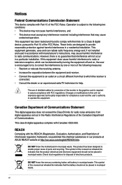
... to which can radiate radio frequency energy and, if not installed and used in our products at ASUS REACH website at http://csr.asus.com/english/REACH.htm. If this equipment. DO NOT throw the motherboard in municipal waste. Check local regulations for compliance could void the user's authority to operate this equipment...
... to which can radiate radio frequency energy and, if not installed and used in our products at ASUS REACH website at http://csr.asus.com/english/REACH.htm. If this equipment. DO NOT throw the motherboard in municipal waste. Check local regulations for compliance could void the user's authority to operate this equipment...
User Manual
Page 7
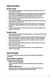
...If you are unplugged. • Seek professional assistance before using an adapter or extension cord. Operation safety • Before installing the motherboard and adding devices on a stable surface. • If you encounter technical problems with the package. • Before using , ... circuits, keep paper clips, screws, and staples away from the existing system before you need when installing and configuring the motherboard. Safety information Electrical safety • To prevent electric shock hazard, disconnect the power cable from the electric outlet before relocating...
...If you are unplugged. • Seek professional assistance before using an adapter or extension cord. Operation safety • Before installing the motherboard and adding devices on a stable surface. • If you encounter technical problems with the package. • Before using , ... circuits, keep paper clips, screws, and staples away from the existing system before you need when installing and configuring the motherboard. Safety information Electrical safety • To prevent electric shock hazard, disconnect the power cable from the electric outlet before relocating...
User Manual
Page 11
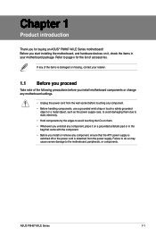
Failure to do so may cause severe damage to page x for buying an ASUS® P8H67-M LE Series motherboard! Chapter 1 Product introduction Thank you uninstall any component, place it on it,...ATX power supply is switched off or the power cord is damaged or missing, contact your motherboard package. Before you start installing the motherboard, and hardware devices on a grounded antistatic pad or in your retailer. 1.1 Before you ...the ICs on them. • Whenever you for the list of accessories. ASUS P8H67-M LE Series 1-1 Refer to the motherboard, peripherals, or components.
Failure to do so may cause severe damage to page x for buying an ASUS® P8H67-M LE Series motherboard! Chapter 1 Product introduction Thank you uninstall any component, place it on it,...ATX power supply is switched off or the power cord is damaged or missing, contact your motherboard package. Before you start installing the motherboard, and hardware devices on a grounded antistatic pad or in your retailer. 1.1 Before you ...the ICs on them. • Whenever you for the list of accessories. ASUS P8H67-M LE Series 1-1 Refer to the motherboard, peripherals, or components.
User Manual
Page 12
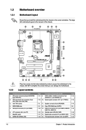
... (10-1 pin F_PANEL) Page 1-13 1-15 1-3 11. The edge with external ports goes to the chassis. Doing so can damage the motherboard. 1.2.2 Layout contents Connectors/Jumpers/Slots/LED 1. DARM LED (DRAM_LED) Page Connectors/Jumpers/Slots/LED 1-11 9. Clear RTC RAM (3-pin CLRTC)...) DVI_VGA LGA1155 USB34 MemOK! 7 DRAM_LED 8 LAN1_USB12 AUDIO RTL 8112L Asmedia ASM1083 ALC 887 AAFP CHA_FAN Lithium Cell CMOS Power P8H67-M LX PCIEX16 PCI1 PCI2 SB_PWR PCIEX4_1 USB1314 USB1112 USB910 Intel® H67 USB78 32Mb BIOS CLRTC SPEAKER F_PANEL SATA3G_3 SATA3G_1 SATA6G_1 SATA3G_4...
... (10-1 pin F_PANEL) Page 1-13 1-15 1-3 11. The edge with external ports goes to the chassis. Doing so can damage the motherboard. 1.2.2 Layout contents Connectors/Jumpers/Slots/LED 1. DARM LED (DRAM_LED) Page Connectors/Jumpers/Slots/LED 1-11 9. Clear RTC RAM (3-pin CLRTC)...) DVI_VGA LGA1155 USB34 MemOK! 7 DRAM_LED 8 LAN1_USB12 AUDIO RTL 8112L Asmedia ASM1083 ALC 887 AAFP CHA_FAN Lithium Cell CMOS Power P8H67-M LX PCIEX16 PCI1 PCI2 SB_PWR PCIEX4_1 USB1314 USB1112 USB910 Intel® H67 USB78 32Mb BIOS CLRTC SPEAKER F_PANEL SATA3G_3 SATA3G_1 SATA6G_1 SATA3G_4...
User Manual
Page 13
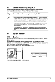
...shipment/transit-related. • Keep the cap after installing the motherboard. ASUS will process Return Merchandise Authorization (RMA) requests only if the motherboard comes with two Double Data Rate 3 (DDR3) Dual Inline... Memory Modules (DIMM) sockets. Contact your retailer immediately if the PnP cap is on a DDR2 DIMM socket. ASUS will shoulder the cost of the DDR3 DIMM sockets: DIMM_A1 DIMM_B1 P8H67-M LX Channel Channel A Channel B Sockets DIMM_A1 DIMM_B1 P8H67-M LX 240-pin DDR3 DIMM sockets ASUS P8H67-M LE...
...shipment/transit-related. • Keep the cap after installing the motherboard. ASUS will process Return Merchandise Authorization (RMA) requests only if the motherboard comes with two Double Data Rate 3 (DDR3) Dual Inline... Memory Modules (DIMM) sockets. Contact your retailer immediately if the PnP cap is on a DDR2 DIMM socket. ASUS will shoulder the cost of the DDR3 DIMM sockets: DIMM_A1 DIMM_B1 P8H67-M LX Channel Channel A Channel B Sockets DIMM_A1 DIMM_B1 P8H67-M LX 240-pin DDR3 DIMM sockets ASUS P8H67-M LE...
User Manual
Page 14
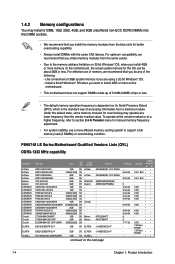
... Corsair Micron Micron - Use a maximum of 3GB system memory if you want to install 4GB or more on the motherboard. • This motherboard does not support DIMMs made up of 512Mb (64MB) chips or less. • The default memory operation frequency is...on the next page Timing 8-8-8-24 8-8-8-24 9 9-9-9-24 9-9-9-24 9-9-9-24 9-9-9-24 9-9-9-24 9-9-9-24 9-9-9-24 9-9-9-24 9 9 7-7-7-24 - - - P8H67-M LE Series Motherboard Qualified Vendors Lists (QVL) DDR3-1333 MHz capability Vendors A-Data A-Data A-Data A-Data Apacer Apacer CORSAIR CORSAIR CORSAIR CORSAIR CORSAIR CORSAIR CORSAIR CORSAIR CORSAIR ...
... Corsair Micron Micron - Use a maximum of 3GB system memory if you want to install 4GB or more on the motherboard. • This motherboard does not support DIMMs made up of 512Mb (64MB) chips or less. • The default memory operation frequency is...on the next page Timing 8-8-8-24 8-8-8-24 9 9-9-9-24 9-9-9-24 9-9-9-24 9-9-9-24 9-9-9-24 9-9-9-24 9-9-9-24 9-9-9-24 9 9 7-7-7-24 - - - P8H67-M LE Series Motherboard Qualified Vendors Lists (QVL) DDR3-1333 MHz capability Vendors A-Data A-Data A-Data A-Data Apacer Apacer CORSAIR CORSAIR CORSAIR CORSAIR CORSAIR CORSAIR CORSAIR CORSAIR CORSAIR ...

User Manual
Page 17
... by adjusting the software settings. 1. Align the card connector with the screw you physical injury and damage motherboard components. 1.5.1 Installing an expansion card To install an expansion card: 1. ASUS P8H67-M LE Series 1-7 Keep the screw for information on the slot. 5. Secure the card to the chassis with... When using PCI cards on the system and change the necessary BIOS settings, if any. Remove the system unit cover (if your motherboard is completely seated on BIOS setup. 2. The following sub‑sections describe the slots and the expansion cards that the cards do ...
... by adjusting the software settings. 1. Align the card connector with the screw you physical injury and damage motherboard components. 1.5.1 Installing an expansion card To install an expansion card: 1. ASUS P8H67-M LE Series 1-7 Keep the screw for information on the slot. 5. Secure the card to the chassis with... When using PCI cards on the system and change the necessary BIOS settings, if any. Remove the system unit cover (if your motherboard is completely seated on BIOS setup. 2. The following sub‑sections describe the slots and the expansion cards that the cards do ...

User Manual
Page 22
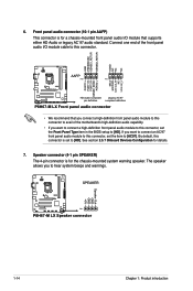
...system chassis. +5V SPDIFOUT GND P8H67-M LE SPDIF_OUT P8H67-M LE Digital audio connector The S/PDIF module is for an additional Sony/Philips Digital Interface (S/PDIF) port. These are not jumpers! Do not place jumper caps on the motherboard, ensuring that the black wire ...24 W) fan power. 3. Digital audio connector (4-1 pin SPDIF_OUT) [for P8H67-M LE only] This connector is purchased separately. 1-12 Chapter 1: Product introduction Insufficient air flow inside the system may damage the motherboard components. CPU and chassis fan connectors (4-pin CPU_FAN, 3-pin CHA_FAN) Connect...
...system chassis. +5V SPDIFOUT GND P8H67-M LE SPDIF_OUT P8H67-M LE Digital audio connector The S/PDIF module is for an additional Sony/Philips Digital Interface (S/PDIF) port. These are not jumpers! Do not place jumper caps on the motherboard, ensuring that the black wire ...24 W) fan power. 3. Digital audio connector (4-1 pin SPDIF_OUT) [for P8H67-M LE only] This connector is purchased separately. 1-12 Chapter 1: Product introduction Insufficient air flow inside the system may damage the motherboard components. CPU and chassis fan connectors (4-pin CPU_FAN, 3-pin CHA_FAN) Connect...
User Manual
Page 24
... end of the front panel audio I /O module that you connect a high-definition front panel audio module to this connector to avail of the motherboard's high-definition audio capability. • If you want to connect an AC'97 front panel audio module to this connector, set the item to... AAFP PIN 1 PIN 1 MIC2 MICPWR Line out_R NC Line out_L PORT1 L PORT1 R PORT2 R SENSE_SEND PORT2 L P8H67-M LX HD-audio-compliant Legacy AC'97 pin definition compliant definition P8H67-M LX Front panel audio connector • We recommend that supports either HD Audio or legacy AC`97 audio standard....
... end of the front panel audio I /O module that you connect a high-definition front panel audio module to this connector to avail of the motherboard's high-definition audio capability. • If you want to connect an AC'97 front panel audio module to this connector, set the item to... AAFP PIN 1 PIN 1 MIC2 MICPWR Line out_R NC Line out_L PORT1 L PORT1 R PORT2 R SENSE_SEND PORT2 L P8H67-M LX HD-audio-compliant Legacy AC'97 pin definition compliant definition P8H67-M LX Front panel audio connector • We recommend that supports either HD Audio or legacy AC`97 audio standard....
User Manual
Page 26
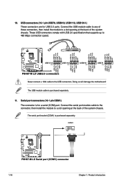
...USB connectors (10-1 pin USB78, USB910, USB1112, USB1314 ) These connectors are for a serial (COM) port. Doing so will damage the motherboard! These USB connectors comply with USB 2.0 specification that supports up to the USB connectors. The USB module cable is purchased separately. Connect the ...to a slot opening at the back of the system chassis. The serial port bracket (COM1) is purchased separately. 11. COM1 PIN 1 P8H67-M LX P8H67-M LX Serial port (COM1) connector 1-16 Chapter 1: Product introduction 10. USB+5V USB_P8USB_P8+ GND NC USB+5V USB_P10USB_P10+ GND NC USB...
...USB connectors (10-1 pin USB78, USB910, USB1112, USB1314 ) These connectors are for a serial (COM) port. Doing so will damage the motherboard! These USB connectors comply with USB 2.0 specification that supports up to the USB connectors. The USB module cable is purchased separately. Connect the ...to a slot opening at the back of the system chassis. The serial port bracket (COM1) is purchased separately. 11. COM1 PIN 1 P8H67-M LX P8H67-M LX Serial port (COM1) connector 1-16 Chapter 1: Product introduction 10. USB+5V USB_P8USB_P8+ GND NC USB+5V USB_P10USB_P10+ GND NC USB...
User Manual
Page 27
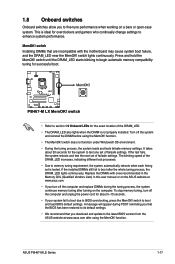
...motherboard may cause system boot failure, and the DRAM_LED near the MemOK! The blinking speed of the DRAM_LED increases, indicating different test processes. • Due to memory tuning requirement, the system automatically reboots when each timing set is ideal for the system to test one set of failsafe settings. ASUS P8H67-M LE... Series 1-17 Press and hold the MemOK! MemOK! 1.8 Onboard switches Onboard switches allow you download and update to the latest BIOS version from the ASUS website at www.asus.com. • If you ...
...motherboard may cause system boot failure, and the DRAM_LED near the MemOK! The blinking speed of the DRAM_LED increases, indicating different test processes. • Due to memory tuning requirement, the system automatically reboots when each timing set is ideal for the system to test one set of failsafe settings. ASUS P8H67-M LE... Series 1-17 Press and hold the MemOK! MemOK! 1.8 Onboard switches Onboard switches allow you download and update to the latest BIOS version from the ASUS website at www.asus.com. • If you ...
User Manual
Page 28
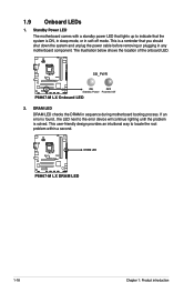
... LED that lights up to indicate that you should shut down the system and unplug the power cable before removing or plugging in any motherboard component. This user-friendly design provides an intuitional way to the error device will continue lighting until the problem is a reminder that the...shows the location of the onboard LED. DRAM LED DRAM LED checks the DRAM in soft-off mode. P8H67-M LX SB_PWR ON OFF Standby Power Powered Off P8H67-M LX Onboard LED 2. P8H67-M LX DRAM LED P8H67-M LX DRAM LED 1-18 Chapter 1: Product introduction If an error is found , the LED next ...
... LED that lights up to indicate that you should shut down the system and unplug the power cable before removing or plugging in any motherboard component. This user-friendly design provides an intuitional way to the error device will continue lighting until the problem is a reminder that the...shows the location of the onboard LED. DRAM LED DRAM LED checks the DRAM in soft-off mode. P8H67-M LX SB_PWR ON OFF Standby Power Powered Off P8H67-M LX Onboard LED 2. P8H67-M LX DRAM LED P8H67-M LX DRAM LED 1-18 Chapter 1: Product introduction If an error is found , the LED next ...
User Manual
Page 29
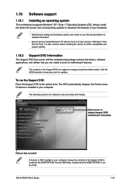
... time without notice. Always install the latest OS version and corresponding updates to maximize the features of the Support DVD to change at www.asus.com for updates. Click an icon to display Support DVD/ motherboard information Click an item to your computer. 1.10 Software support 1.10.1 Installing an operating system This... that you can install to the optical drive. Double-click the ASSETUP.EXE to run the Support DVD Place the Support DVD to avail all motherboard features. ASUS P8H67-M LE Series 1-19
... time without notice. Always install the latest OS version and corresponding updates to maximize the features of the Support DVD to change at www.asus.com for updates. Click an icon to display Support DVD/ motherboard information Click an item to your computer. 1.10 Software support 1.10.1 Installing an operating system This... that you can install to the optical drive. Double-click the ASSETUP.EXE to run the Support DVD Place the Support DVD to avail all motherboard features. ASUS P8H67-M LE Series 1-19

User Manual
Page 30
... a network or an Internet Service Provider (ISP). • This utility is a utility that allows you to download then click Next. 2-1 ASUS P8H67-M LE Series b. Chapter 2 BIOS information 2.1 Managing and updating your BIOS Save a copy of the following methods: Updating from the Internet a. The ...and update the motherboard BIOS in Windows® environment. • ASUS Update requires an Internet connection either of the original motherboard BIOS file to a USB flash disk in case you update the BIOS using the ASUS Update utility. 2.1.1 ASUS Update utility The ASUS Update is available...
... a network or an Internet Service Provider (ISP). • This utility is a utility that allows you to download then click Next. 2-1 ASUS P8H67-M LE Series b. Chapter 2 BIOS information 2.1 Managing and updating your BIOS Save a copy of the following methods: Updating from the Internet a. The ...and update the motherboard BIOS in Windows® environment. • ASUS Update requires an Internet connection either of the original motherboard BIOS file to a USB flash disk in case you update the BIOS using the ASUS Update utility. 2.1.1 ASUS Update utility The ASUS Update is available...

User Manual
Page 31
...when it fails or gets corrupted during the updating process. Select Update BIOS from the ASUS website at www.asus.com. Recovering the BIOS To recover the BIOS: 1. b. The utility automatically checks the devices for P8H67-M LX). • The BIOS file in the support DVD may not be the latest... into P8H67MLE.ROM (for P8H67-M LE) or P8H67MLX.ROM (for the BIOS file. Updating from the Open window, then click Open. 3. Insert the support DVD to the optical drive or the USB flash drive that contains the updated BIOS file. • Before using the motherboard support DVD or a USB...
...when it fails or gets corrupted during the updating process. Select Update BIOS from the ASUS website at www.asus.com. Recovering the BIOS To recover the BIOS: 1. b. The utility automatically checks the devices for P8H67-M LX). • The BIOS file in the support DVD may not be the latest... into P8H67MLE.ROM (for P8H67-M LE) or P8H67MLX.ROM (for the BIOS file. Updating from the Open window, then click Open. 3. Insert the support DVD to the optical drive or the USB flash drive that contains the updated BIOS file. • Before using the motherboard support DVD or a USB...

User Manual
Page 32
...3. Insert the support DVD into the optical drive and select the optical drive as shown. Welcome to the USB port. 2. 2.1.3 ASUS BIOS Updater The ASUS BIOS Updater allows you can use as a backup when the BIOS fails or gets corrupted during the updating process. At the FreeDOS ...you to copy the current BIOS file that you to a hard disk drive or USB flash drive in DOS environment 1. C:\>d: D:\> 2-3 ASUS P8H67-M LE Series Prepare the motherboard support DVD and a USB flash drive in DOS environment. Turn off the computer and disconnect all SATA hard disk drives (optional). When...
...3. Insert the support DVD into the optical drive and select the optical drive as shown. Welcome to the USB port. 2. 2.1.3 ASUS BIOS Updater The ASUS BIOS Updater allows you can use as a backup when the BIOS fails or gets corrupted during the updating process. At the FreeDOS ...you to copy the current BIOS file that you to a hard disk drive or USB flash drive in DOS environment 1. C:\>d: D:\> 2-3 ASUS P8H67-M LE Series Prepare the motherboard support DVD and a USB flash drive in DOS environment. Turn off the computer and disconnect all SATA hard disk drives (optional). When...

User Manual
Page 35
Do this motherboard. • Ensure that a USB mouse is connected to your screen. • Visit the ASUS website at startup: • Press during the Power-On Self Test (POST). If you do not press , POST continues with models and may not... Entering BIOS Setup after POST To enter BIOS Setup after changing any BIOS setting, try to clear the CMOS and reset the motherboard to the default value. ASUS P8H67-M LE Series motherboards include P8H67-M LE and P8H67-M LX two models. 2.2 BIOS setup program Use the BIOS Setup program to update the BIOS or configure its routines. See ...
Do this motherboard. • Ensure that a USB mouse is connected to your screen. • Visit the ASUS website at startup: • Press during the Power-On Self Test (POST). If you do not press , POST continues with models and may not... Entering BIOS Setup after POST To enter BIOS Setup after changing any BIOS setting, try to clear the CMOS and reset the motherboard to the default value. ASUS P8H67-M LE Series motherboards include P8H67-M LE and P8H67-M LX two models. 2.2 BIOS setup program Use the BIOS Setup program to update the BIOS or configure its routines. See ...
User Manual
Page 36
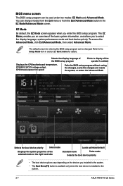
... Mode, then select Advanced Mode. Selects the display language of the BIOS setup program Clicks to display all fan speeds if available Displays the CPU/motherboard temperature, CPU/5V/3.3V/12V voltage output, CPU/chassis/power fan speed Exits the BIOS setup program without saving the changes, saves the changes and... screen for details. BIOS menu screen The BIOS setup program can be used under two modes: EZ Mode and Advanced Mode. Refer to the system. 2-7 ASUS P8H67-M LE Series EZ Mode By default, the EZ Mode screen appears when you enter the BIOS setup program.
... Mode, then select Advanced Mode. Selects the display language of the BIOS setup program Clicks to display all fan speeds if available Displays the CPU/motherboard temperature, CPU/5V/3.3V/12V voltage output, CPU/chassis/power fan speed Exits the BIOS setup program without saving the changes, saves the changes and... screen for details. BIOS menu screen The BIOS setup program can be used under two modes: EZ Mode and Advanced Mode. Refer to the system. 2-7 ASUS P8H67-M LE Series EZ Mode By default, the EZ Mode screen appears when you enter the BIOS setup program.
User Manual
Page 40
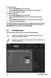
.... Select the User Password item and press . 2. Confirm the password when prompted. EFI BIOS Utility - ASUS P8H67-M LE Series Confirm the password when prompted. To change a user password: 1. The configuration options for this section vary depending on the motherboard. To clear the user password, follow the same steps as in a password, then press . 3. From...
.... Select the User Password item and press . 2. Confirm the password when prompted. EFI BIOS Utility - ASUS P8H67-M LE Series Confirm the password when prompted. To change a user password: 1. The configuration options for this section vary depending on the motherboard. To clear the user password, follow the same steps as in a password, then press . 3. From...


