
P8H61-MX R2.0 User's Manual
Page 1
Motherboard P8H61-MX Series • P8H61-MX R2.0 • P8H61-MX USB3
Motherboard P8H61-MX Series • P8H61-MX R2.0 • P8H61-MX USB3
P8H61-MX R2.0 User's Manual
Page 3
Contents Safety information vi About this guide vii P8H61-MX Series specifications summary ix Chapter 1 Product introduction 1.1 Before you proceed 1-1 1.2 Motherboard overview 1-2 1.2.1 Placement direction 1-2 1.2.2 Screw holes 1-2 1.2.3 Motherboard layout 1-3 1.2.4 Layout contents 1-4 1.3 Central Processing Unit (CPU 1-5 1.3.1 Installing the CPU 1-5 1.3.2 Installing the CPU heatsink and fan 1-8 1.3.3 Uninstalling the CPU heatsink and fan 1-9 1.4 System memory 1-10 1.4.1 ...
Contents Safety information vi About this guide vii P8H61-MX Series specifications summary ix Chapter 1 Product introduction 1.1 Before you proceed 1-1 1.2 Motherboard overview 1-2 1.2.1 Placement direction 1-2 1.2.2 Screw holes 1-2 1.2.3 Motherboard layout 1-3 1.2.4 Layout contents 1-4 1.3 Central Processing Unit (CPU 1-5 1.3.1 Installing the CPU 1-5 1.3.2 Installing the CPU heatsink and fan 1-8 1.3.3 Uninstalling the CPU heatsink and fan 1-9 1.4 System memory 1-10 1.4.1 ...
P8H61-MX R2.0 User's Manual
Page 6
.... If you are not sure about the voltage of the electrical outlet you add a device. • Before connecting or removing signal cables from the motherboard, ensure that your area. Do not place the product in your power supply is broken, do not try to fix it by yourself. Contact a... qualified service technician or your retailer. Operation safety • Before installing the motherboard and adding devices on it may become wet. • Place the product on a stable surface. • If you detect any area where it , ...
.... If you are not sure about the voltage of the electrical outlet you add a device. • Before connecting or removing signal cables from the motherboard, ensure that your area. Do not place the product in your power supply is broken, do not try to fix it by yourself. Contact a... qualified service technician or your retailer. Operation safety • Before installing the motherboard and adding devices on it may become wet. • Place the product on a stable surface. • If you detect any area where it , ...
P8H61-MX R2.0 User's Manual
Page 7
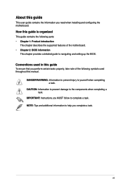
...throughout this guide is organized This guide contains the following symbols used in this guide To ensure that you need when installing and configuring the motherboard. DANGER/WARNING: Information to prevent injury to the components when completing a task. NOTE: Tips and additional information to help you MUST follow... tasks properly, take note of the following parts: • Chapter 1: Product introduction This chapter describes the supported features of the motherboard. • Chapter 2: BIOS information This chapter provides a detailed guide to navigating and setting up the BIOS.
...throughout this guide is organized This guide contains the following symbols used in this guide To ensure that you need when installing and configuring the motherboard. DANGER/WARNING: Information to prevent injury to the components when completing a task. NOTE: Tips and additional information to help you MUST follow... tasks properly, take note of the following parts: • Chapter 1: Product introduction This chapter describes the supported features of the motherboard. • Chapter 2: BIOS information This chapter provides a detailed guide to navigating and setting up the BIOS.
P8H61-MX R2.0 User's Manual
Page 11
... the ICs on them. • Whenever you for buying an ASUS® P8H61-MX Series motherboard! P8H61-MX R2.0 SB_PWR ON OFF Standby Power Powered Off P8H61-MX Series Onboard LED Chapter 1: Product introduction 1-1 Standby Power LED The motherboard comes with the component. • Before you should shut down ...switched off or the power cord is ON, in sleep mode, or in your retailer. • ASUS P8H61-MX Series motherboards include P8H61-MX R2.0 and P8H61-MX USB3 models. Chapter 1 Product introduction Thank you uninstall any component, place it on a grounded antistatic pad or in ...
... the ICs on them. • Whenever you for buying an ASUS® P8H61-MX Series motherboard! P8H61-MX R2.0 SB_PWR ON OFF Standby Power Powered Off P8H61-MX Series Onboard LED Chapter 1: Product introduction 1-1 Standby Power LED The motherboard comes with the component. • Before you should shut down ...switched off or the power cord is ON, in sleep mode, or in your retailer. • ASUS P8H61-MX Series motherboards include P8H61-MX R2.0 and P8H61-MX USB3 models. Chapter 1 Product introduction Thank you uninstall any component, place it on a grounded antistatic pad or in ...
P8H61-MX R2.0 User's Manual
Page 12
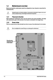
... as indicated in the correct orientation. The edge with external ports goes to the rear part of your chassis to do so can damage the motherboard. Place this side towards the rear of the chassis P8H61-MX R2.0 1-2 ASUS P8H61-MX Series Failure to ensure that the motherboard fits. Unplug the power cord before installing or removing the...
... as indicated in the correct orientation. The edge with external ports goes to the rear part of your chassis to do so can damage the motherboard. Place this side towards the rear of the chassis P8H61-MX R2.0 1-2 ASUS P8H61-MX Series Failure to ensure that the motherboard fits. Unplug the power cord before installing or removing the...
P8H61-MX R2.0 User's Manual
Page 15
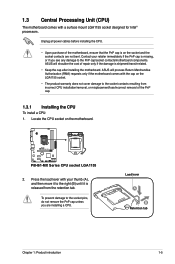
...CPU: 1. P8H61-MX R2.0 P8H61-MX Series CPU socket LGA1155 2. Locate the CPU socket on the LGA1155 socket. • The product warranty does not cover damage to the socket contacts resulting from the retention tab. To prevent damage to the PnP cap/socket contacts/motherboard components. ASUS will shoulder... the cost of the motherboard, ensure that the PnP cap is on the socket and the socket contacts are installing a CPU. Load...
...CPU: 1. P8H61-MX R2.0 P8H61-MX Series CPU socket LGA1155 2. Locate the CPU socket on the LGA1155 socket. • The product warranty does not cover damage to the socket contacts resulting from the retention tab. To prevent damage to the PnP cap/socket contacts/motherboard components. ASUS will shoulder... the cost of the motherboard, ensure that the PnP cap is on the socket and the socket contacts are installing a CPU. Load...
P8H61-MX R2.0 User's Manual
Page 18
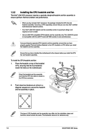
... the installation steps and functions should remain the same. Place the heatsink on the motherboard. To install the CPU heatsink and fan: 1. B Orient the heatsink and fan assembly A such that the CPU fan cable is for reference only. 1-8 ASUS P8H61-MX Series 1.3.2 Installing the CPU heatsink and fan The Intel® LGA1155 processor requires...
... the installation steps and functions should remain the same. Place the heatsink on the motherboard. To install the CPU heatsink and fan: 1. B Orient the heatsink and fan assembly A such that the CPU fan cable is for reference only. 1-8 ASUS P8H61-MX Series 1.3.2 Installing the CPU heatsink and fan The Intel® LGA1155 processor requires...
P8H61-MX R2.0 User's Manual
Page 19
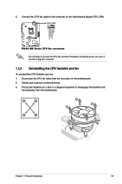
... fail to disengage the heatsink and fan assembly from the connector on the motherboard labeled CPU_FAN. CPU_FAN CPU FAN PWM CPU FAN IN CPU FAN PWR GND P8H61-MX R2.0 P8H61-MX Series CPU fan connector Do not forget to the connector on the motherboard. 2. A B B A A B B A Chapter 1: Product introduction 1-9 3. Rotate each fastener counterclockwise. 3. Connect the CPU fan cable...
... fail to disengage the heatsink and fan assembly from the connector on the motherboard labeled CPU_FAN. CPU_FAN CPU FAN PWM CPU FAN IN CPU FAN PWR GND P8H61-MX R2.0 P8H61-MX Series CPU fan connector Do not forget to the connector on the motherboard. 2. A B B A A B B A Chapter 1: Product introduction 1-9 3. Rotate each fastener counterclockwise. 3. Connect the CPU fan cable...
P8H61-MX R2.0 User's Manual
Page 20
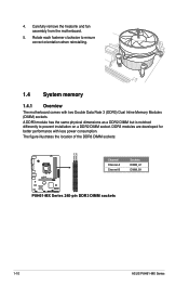
... the DDR3 DIMM sockets: DIMM_A1 DIMM_B1 P8H61-MX R2.0 Channel Channel A Channel B Sockets DIMM_A1 DIMM_B1 P8H61-MX Series 240-pin DDR3 DIMM sockets 1-10 ASUS P8H61-MX Series A DDR3 module has the same physical dimensions as a DDR2 DIMM but is notched differently to ensure correct orientation when reinstalling. 1.4 System memory 1.4.1 Overview The motherboard comes with less power consumption. DDR3...
... the DDR3 DIMM sockets: DIMM_A1 DIMM_B1 P8H61-MX R2.0 Channel Channel A Channel B Sockets DIMM_A1 DIMM_B1 P8H61-MX Series 240-pin DDR3 DIMM sockets 1-10 ASUS P8H61-MX Series A DDR3 module has the same physical dimensions as a DDR2 DIMM but is notched differently to ensure correct orientation when reinstalling. 1.4 System memory 1.4.1 Overview The motherboard comes with less power consumption. DDR3...
P8H61-MX R2.0 User's Manual
Page 21
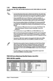
... effective use of accessing information from a memory module. Profile is then mapped for the OS can be about 3GB or less. P8H61-MX Series Motherboard Qualified Vendors Lists (QVL) DDR3-1066 MHz capability Vendors Part No. Under the default state, some memory modules for overclocking may ... manual memory frequency adjustment. • For system stability, use 512Mb (64MB) chips or less. • Memory modules with 8GB or above DIMMs. ASUS will update the memory QVL once the DIMMs are using a 32-bit Windows® OS. - Timing Voltage DIMM socket support (Optional) A* B*...
... effective use of accessing information from a memory module. Profile is then mapped for the OS can be about 3GB or less. P8H61-MX Series Motherboard Qualified Vendors Lists (QVL) DDR3-1066 MHz capability Vendors Part No. Under the default state, some memory modules for overclocking may ... manual memory frequency adjustment. • For system stability, use 512Mb (64MB) chips or less. • Memory modules with 8GB or above DIMMs. ASUS will update the memory QVL once the DIMMs are using a 32-bit Windows® OS. - Timing Voltage DIMM socket support (Optional) A* B*...
P8H61-MX R2.0 User's Manual
Page 27
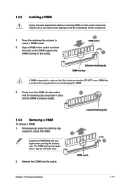
... a DIMM on the socket such that it flips out with your fingers when pressing the retaining clips. Press the retaining clips outward to both the motherboard and the components. 1. Simultaneously press the retaining clips outward to avoid damaging the DIMM. 3. Locked Retaining Clip 2 1 DIMM notch Chapter 1: Product introduction 1-17...
... a DIMM on the socket such that it flips out with your fingers when pressing the retaining clips. Press the retaining clips outward to both the motherboard and the components. 1. Simultaneously press the retaining clips outward to avoid damaging the DIMM. 3. Locked Retaining Clip 2 1 DIMM notch Chapter 1: Product introduction 1-17...
P8H61-MX R2.0 User's Manual
Page 28
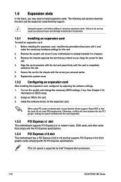
... you physical injury and damage motherboard components. 1.5.1 Installing an expansion card To install an expansion card: 1. Secure the card to the card. 3. Before installing the expansion card, read the documentation that they support. Align the card connector with it by Intel® 3rd generation processors. 1-18 ASUS P8H61-MX Series Unplug the power cord...
... you physical injury and damage motherboard components. 1.5.1 Installing an expansion card To install an expansion card: 1. Secure the card to the card. 3. Before installing the expansion card, read the documentation that they support. Align the card connector with it by Intel® 3rd generation processors. 1-18 ASUS P8H61-MX Series Unplug the power cord...

P8H61-MX R2.0 User's Manual
Page 32
...See section 2.5.6 Onboard Devices Configuration for details. 1-22 ASUS P8H61-MX Series Find the proper orientation and push down firmly until...EATX12V EATXPWR +12V DC +12V DC P8H61-MX R2.0 GND GND +3 Volts +12 Volts +12 Volts +5V Standby Power...P8H61-MX Series ATX power connectors GND +5 Volts +5 Volts +5 Volts -5 Volts GND GND GND PSON# GND -12 Volts +3 Volts • For a fully configured system, we recommend that you use a PSU with higher power output when configuring a system with ATX 12 V Specification 2.0 (or later version) and provides a minimum power of the motherboard...
...See section 2.5.6 Onboard Devices Configuration for details. 1-22 ASUS P8H61-MX Series Find the proper orientation and push down firmly until...EATX12V EATXPWR +12V DC +12V DC P8H61-MX R2.0 GND GND +3 Volts +12 Volts +12 Volts +5V Standby Power...P8H61-MX Series ATX power connectors GND +5 Volts +5 Volts +5 Volts -5 Volts GND GND GND PSON# GND -12 Volts +3 Volts • For a fully configured system, we recommend that you use a PSU with higher power output when configuring a system with ATX 12 V Specification 2.0 (or later version) and provides a minimum power of the motherboard...
P8H61-MX R2.0 User's Manual
Page 33
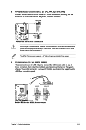
... speed. USB+5V USB_P6USB_P6+ GND NC USB+5V USB_P8USB_P8+ GND NC USB78 USB910 USB+5V USB_P5USB_P5+ GND USB+5V USB_P7USB_P7+ GND P8H61-MX R2.0 PIN 1 PIN 1 P8H61-MX Series USB2.0 connectors Chapter 1: Product introduction 1-23 These are for USB 2.0 ports. These USB connectors comply with USB 2.0 specification ...Do not place jumper caps on the motherboard, ensuring that supports up to a slot opening at the back of maximum 2A (24 W) fan power. 4. CPU_FAN CPU FAN PWM CPU FAN IN CPU FAN PWR GND P8H61-MX R2.0 CHA_FAN Rotation +12V GND P8H61-MX Series Fan connectors Do not forget to...
... speed. USB+5V USB_P6USB_P6+ GND NC USB+5V USB_P8USB_P8+ GND NC USB78 USB910 USB+5V USB_P5USB_P5+ GND USB+5V USB_P7USB_P7+ GND P8H61-MX R2.0 PIN 1 PIN 1 P8H61-MX Series USB2.0 connectors Chapter 1: Product introduction 1-23 These are for USB 2.0 ports. These USB connectors comply with USB 2.0 specification ...Do not place jumper caps on the motherboard, ensuring that supports up to a slot opening at the back of maximum 2A (24 W) fan power. 4. CPU_FAN CPU FAN PWM CPU FAN IN CPU FAN PWR GND P8H61-MX R2.0 CHA_FAN Rotation +12V GND P8H61-MX Series Fan connectors Do not forget to...
P8H61-MX R2.0 User's Manual
Page 34
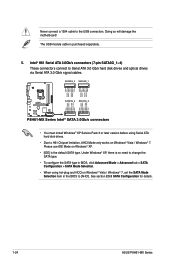
... Selection item in the BIOS to [AHCI]. See section 2.5.3 SATA Configuration for details. 1-24 ASUS P8H61-MX Series Doing so will damage the motherboard! SATA3G_3 SATA3G_1 GND RSATA_TXP3 RSATA_TXN3 GND RSATA_RXN3 RSATA_RXP3 GND GND RSATA_TXP1 RSATA_TXN1 GND RSATA_RXN1 RSATA_RXP1 GND P8H61-MX R2.0 SATA3G_4 SATA3G_2 GND RSATA_RXP4 RSATA_RXN4 GND RSATA_TXN4 RSATA_TXP4 GND GND RSATA_RXP2 RSATA_RXN2 GND RSATA_TXN2...
... Selection item in the BIOS to [AHCI]. See section 2.5.3 SATA Configuration for details. 1-24 ASUS P8H61-MX Series Doing so will damage the motherboard! SATA3G_3 SATA3G_1 GND RSATA_TXP3 RSATA_TXN3 GND RSATA_RXN3 RSATA_RXP3 GND GND RSATA_TXP1 RSATA_TXN1 GND RSATA_RXN1 RSATA_RXP1 GND P8H61-MX R2.0 SATA3G_4 SATA3G_2 GND RSATA_RXP4 RSATA_RXN4 GND RSATA_TXN4 RSATA_TXP4 GND GND RSATA_RXP2 RSATA_RXN2 GND RSATA_TXN2...
P8H61-MX R2.0 User's Manual
Page 36
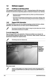
...before installing the drivers for reference only. Click an icon to display Support DVD/ motherboard information Click an item to change at www.asus.com for updates. To run the DVD. 1-26 ASUS P8H61-MX Series Always install the latest OS version and corresponding updates to maximize the features of... the Support DVD to avail all motherboard features. Refer to your computer, the DVD ...
...before installing the drivers for reference only. Click an icon to display Support DVD/ motherboard information Click an item to change at www.asus.com for updates. To run the DVD. 1-26 ASUS P8H61-MX Series Always install the latest OS version and corresponding updates to maximize the features of... the Support DVD to avail all motherboard features. Refer to your computer, the DVD ...
P8H61-MX R2.0 User's Manual
Page 37
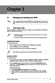
... Service Provider (ISP). • This utility is a utility that allows you to manage, save, and update the motherboard BIOS in a Windows® environment. • ASUS Update requires an Internet connection either of the original motherboard BIOS file to a USB flash disk in case you need to restore the BIOS in the support DVD...
... Service Provider (ISP). • This utility is a utility that allows you to manage, save, and update the motherboard BIOS in a Windows® environment. • ASUS Update requires an Internet connection either of the original motherboard BIOS file to a USB flash disk in case you need to restore the BIOS in the support DVD...
P8H61-MX R2.0 User's Manual
Page 39
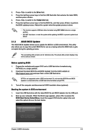
... disk drive or USB flash drive formatted using defaults Chapter 2: BIOS information 2-3 Before updating BIOS 1. Booting the system in a DOS environment. When the ASUS Logo appears, press to copy the current BIOS file for reference only. Insert the support DVD into the USB port. 2. Press the Up/Down arrow...to find the BIOS file, and then press to find the USB flash disk that contains the latest BIOS, and then press . 5. Prepare the motherboard support DVD and a USB flash drive formatted using FAT 16/32 format on a single partition. • DO NOT shut down or reset the system...
... disk drive or USB flash drive formatted using defaults Chapter 2: BIOS information 2-3 Before updating BIOS 1. Booting the system in a DOS environment. When the ASUS Logo appears, press to copy the current BIOS file for reference only. Insert the support DVD into the USB port. 2. Press the Up/Down arrow...to find the BIOS file, and then press to find the USB flash disk that contains the latest BIOS, and then press . 5. Prepare the motherboard support DVD and a USB flash drive formatted using FAT 16/32 format on a single partition. • DO NOT shut down or reset the system...
P8H61-MX R2.0 User's Manual
Page 41
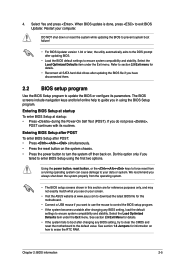
...BIOS Setup at www.asus.com to download the latest BIOS file for this option only if you want to use the mouse to control the BIOS setup program. • If the system becomes unstable after changing any BIOS setting, try to clear the CMOS and reset the motherboard to the default... value. Do this motherboard. • Connect a USB mouse if you failed to your data or system. See section 1.6 Jumpers for reference purposes only, and may...
...BIOS Setup at www.asus.com to download the latest BIOS file for this option only if you want to use the mouse to control the BIOS setup program. • If the system becomes unstable after changing any BIOS setting, try to clear the CMOS and reset the motherboard to the default... value. Do this motherboard. • Connect a USB mouse if you failed to your data or system. See section 1.6 Jumpers for reference purposes only, and may...


