User Manual
Page 3
Contents Notices...vi Safety information vii About this guide viii P8H61-M2 USB3 specifications summary ix Chapter 1: Product introduction 1.1 Before you proceed 1-1 1.2 Motherboard overview 1-2 1.2.1 Placement direction 1-2 1.2.2 Screw holes 1-2 1.2.3 Motherboard layout 1-3 1.2.4 ... an expansion card 1-13 1.5.3 PCI Express x1 slot 1-13 1.5.4 PCI Express x16 slot 1-13 1.6 Jumpers 1-14 1.7 Connectors 1-15 1.7.1 Rear panel connectors 1-15 1.7.2 Internal connectors 1-16 1.8 Software support 1-22 1.8.1 Installing an operating system 1-22 1.8.2 Support DVD information 1-22 iii
Contents Notices...vi Safety information vii About this guide viii P8H61-M2 USB3 specifications summary ix Chapter 1: Product introduction 1.1 Before you proceed 1-1 1.2 Motherboard overview 1-2 1.2.1 Placement direction 1-2 1.2.2 Screw holes 1-2 1.2.3 Motherboard layout 1-3 1.2.4 ... an expansion card 1-13 1.5.3 PCI Express x1 slot 1-13 1.5.4 PCI Express x16 slot 1-13 1.6 Jumpers 1-14 1.7 Connectors 1-15 1.7.1 Rear panel connectors 1-15 1.7.2 Internal connectors 1-16 1.8 Software support 1-22 1.8.1 Installing an operating system 1-22 1.8.2 Support DVD information 1-22 iii

User Manual
Page 7
...Registration, Evaluation, Authorisation, and Restriction of parts and recycling. Do not place the product in our products at ASUS REACH website at http://csr.asus.com/english/REACH.htm. DO NOT throw the motherboard in municipal waste. If possible, disconnect all power cables ... the motherboard and adding devices on a stable surface. • If you add a device. • Before connecting or removing signal cables from connectors, slots, sockets and circuitry. • Avoid dust, humidity, and temperature extremes. REACH Complying with the package. • Before using the product...
...Registration, Evaluation, Authorisation, and Restriction of parts and recycling. Do not place the product in our products at ASUS REACH website at http://csr.asus.com/english/REACH.htm. DO NOT throw the motherboard in municipal waste. If possible, disconnect all power cables ... the motherboard and adding devices on a stable surface. • If you add a device. • Before connecting or removing signal cables from connectors, slots, sockets and circuitry. • Avoid dust, humidity, and temperature extremes. REACH Complying with the package. • Before using the product...

User Manual
Page 9
... 10.1 1 x PCI Express 2.0 x16 slot 2 x PCI Express 2.0 x1 slots Intel® H61 Express Chipset: - 4 x Serial ATA 3.0 Gb/s connectors Realtek® 8111E PCIe Gigabit LAN controller VIA® VT1708S 8-channel* High Definition Audio CODEC - Integrated graphics processor Multi-VGA output support: HDMI and D-Sub...up to 1920 x 1200 @60Hz Supports D-Sub with 8GB or above DIMMs. ASUS will update the memory QVL once the DIMMs are using a Windows® 32-bit operating system. P8H61-M2 USB3 specifications summary CPU Chipset Memory Graphics Expansion slots Storage LAN Audio USB LGA1155 socket ...
... 10.1 1 x PCI Express 2.0 x16 slot 2 x PCI Express 2.0 x1 slots Intel® H61 Express Chipset: - 4 x Serial ATA 3.0 Gb/s connectors Realtek® 8111E PCIe Gigabit LAN controller VIA® VT1708S 8-channel* High Definition Audio CODEC - Integrated graphics processor Multi-VGA output support: HDMI and D-Sub...up to 1920 x 1200 @60Hz Supports D-Sub with 8GB or above DIMMs. ASUS will update the memory QVL once the DIMMs are using a Windows® 32-bit operating system. P8H61-M2 USB3 specifications summary CPU Chipset Memory Graphics Expansion slots Storage LAN Audio USB LGA1155 socket ...

User Manual
Page 10
P8H61-M2 USB3 specifications summary ASUS unique features Rear panel ports Internal connectors/ switches/ buttons BIOS features Accessories Support DVD Form factor ASUS EPU Lite GPU Boost ASUS Anti-Surge Protection ASUS UEFI BIOS ASUS Q-Fan 2 ASUS FanXpert ASUS CrashFree BIOS 3 ASUS EZ Flash 2 ASUS MyLogo 2™ 1 x PS/2 keyboard port (purple) 1 x PS/2 mouse port (green) 1 x HDMI port 1 x D-Sub port 1 x LAN (RJ-45) port 4 x USB...
P8H61-M2 USB3 specifications summary ASUS unique features Rear panel ports Internal connectors/ switches/ buttons BIOS features Accessories Support DVD Form factor ASUS EPU Lite GPU Boost ASUS Anti-Surge Protection ASUS UEFI BIOS ASUS Q-Fan 2 ASUS FanXpert ASUS CrashFree BIOS 3 ASUS EZ Flash 2 ASUS MyLogo 2™ 1 x PS/2 keyboard port (purple) 1 x PS/2 mouse port (green) 1 x HDMI port 1 x D-Sub port 1 x LAN (RJ-45) port 4 x USB...

User Manual
Page 13
... PCIEX16 ASM RTL 8111E 1042 PCIEX1_1 P8H61-M2 USB3 6 Intel® Super I/O PCIEX1_2 H61 SATA3G_1 SB_PWR 7 SATA3G_2 VIA VT1708S AAFP SPDIF_OUT USB56 USB78 CLRTC CHASSIS SPEAKER SATA3G_4 SATA3G_3 F_PANEL 32Mb BIOS 14 13 12 11 10 9 8 1.2.4 Layout contents Connectors/Jumpers/Slots/LED Page Connectors/Jumpers/Slots/LED Page 1. USB 3.0 connector (20-1 pin USB3_12) 6. Standby power LED...
... PCIEX16 ASM RTL 8111E 1042 PCIEX1_1 P8H61-M2 USB3 6 Intel® Super I/O PCIEX1_2 H61 SATA3G_1 SB_PWR 7 SATA3G_2 VIA VT1708S AAFP SPDIF_OUT USB56 USB78 CLRTC CHASSIS SPEAKER SATA3G_4 SATA3G_3 F_PANEL 32Mb BIOS 14 13 12 11 10 9 8 1.2.4 Layout contents Connectors/Jumpers/Slots/LED Page Connectors/Jumpers/Slots/LED Page 1. USB 3.0 connector (20-1 pin USB3_12) 6. Standby power LED...

User Manual
Page 15
... correct orientation. The CPU fits in the direction of the socket, and then fit the socket alignment keys into the socket to prevent bending the connectors on the bottom‑left corner of the arrow until the load plate is on the socket and damaging the CPU! PnP cap 5.
... correct orientation. The CPU fits in the direction of the socket, and then fit the socket alignment keys into the socket to prevent bending the connectors on the bottom‑left corner of the arrow until the load plate is on the socket and damaging the CPU! PnP cap 5.

User Manual
Page 17
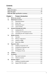
... fan assembly in size and dimension. B B Orient the heatsink and fan assembly A such that you have properly applied Thermal Interface Material to the CPU fan connector. 2. If you install the CPU fan and heatsink assembly. Place the heatsink on the motherboard. The LGA1155 socket is for reference only. If you purchased...
... fan assembly in size and dimension. B B Orient the heatsink and fan assembly A such that you have properly applied Thermal Interface Material to the CPU fan connector. 2. If you install the CPU fan and heatsink assembly. Place the heatsink on the motherboard. The LGA1155 socket is for reference only. If you purchased...
User Manual
Page 18
... cable from the motherboard. 3. CPU_FAN CPU FAN PWM CPU FAN IN CPU FAN PWR GND P8H61-M2 USB3 P8H61-M2 USB3 CPU fan connector Do not forget to the connector on the motherboard. 2. A B A B B A B A 1-8 ASUS P8H61-M2 USB3 Connect the CPU fan cable to connect the CPU fan connector! Hardware monitoring errors can occur if you fail to disengage the heatsink and fan assembly...
... cable from the motherboard. 3. CPU_FAN CPU FAN PWM CPU FAN IN CPU FAN PWR GND P8H61-M2 USB3 P8H61-M2 USB3 CPU fan connector Do not forget to the connector on the motherboard. 2. A B A B B A B A 1-8 ASUS P8H61-M2 USB3 Connect the CPU fan cable to connect the CPU fan connector! Hardware monitoring errors can occur if you fail to disengage the heatsink and fan assembly...

User Manual
Page 23
... seated on shared slots, ensure that the drivers support "Share IRQ" or that the cards do so may need IRQ assignments. shared - - - - - - Align the card connector with the screw you may cause you intend to the card. 3. 1.5 Expansion slots In the future, you removed earlier. 6. IRQ assignments for the expansion card...
... seated on shared slots, ensure that the drivers support "Share IRQ" or that the cards do so may need IRQ assignments. shared - - - - - - Align the card connector with the screw you may cause you intend to the card. 3. 1.5 Expansion slots In the future, you removed earlier. 6. IRQ assignments for the expansion card...

User Manual
Page 25
.../2 mouse port (green). Refer to the audio configuration table below for the LAN port LED indications. LAN (RJ-45) port. Chapter 1: Product introduction 1-15 1.7 1.7.1 1 Connectors Rear panel connectors 2 34 10 9 8 7 6 5 1. LAN port LED indications Activity/Link LED Status Description OFF No link ORANGE Linked BLINKING Data activity Speed LED Status OFF ORANGE...
.../2 mouse port (green). Refer to the audio configuration table below for the LAN port LED indications. LAN (RJ-45) port. Chapter 1: Product introduction 1-15 1.7 1.7.1 1 Connectors Rear panel connectors 2 34 10 9 8 7 6 5 1. LAN port LED indications Activity/Link LED Status Description OFF No link ORANGE Linked BLINKING Data activity Speed LED Status OFF ORANGE...
User Manual
Page 26
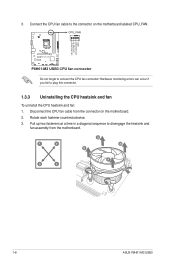
... HD DVD, Blu-ray, and other VGA-compatible devices. 9. 6. These two 4-pin Universal Serial Bus (USB) ports are for details. 1-16 ASUS P8H61-M2 USB3 Front panel audio connector (10-1 pin AAFP) This connector is for a chassis-mounted front panel audio I /O module cable to [AC97]. AGND NC SENSE1_RETUR SENSE2_RETUR AGND NC NC NC AAFP PIN 1 PIN...
... HD DVD, Blu-ray, and other VGA-compatible devices. 9. 6. These two 4-pin Universal Serial Bus (USB) ports are for details. 1-16 ASUS P8H61-M2 USB3 Front panel audio connector (10-1 pin AAFP) This connector is for a chassis-mounted front panel audio I /O module cable to [AC97]. AGND NC SENSE1_RETUR SENSE2_RETUR AGND NC NC NC AAFP PIN 1 PIN...

User Manual
Page 27
... for your system, refer to the Recommended Power Supply Wattage Calculator at http://support.asus. Chapter 1: Product introduction 1-17 ATX power connectors (24-pin EATXPWR, 4-pin ATX12V) These connectors are designed to connect the 4-pin ATX +12V power plug. 2. com/PowerSupplyCalculator/...with more power-consuming devices. ATX12V EATXPWR +12V DC +12V DC P8H61-M2 USB3 GND GND +3 Volts +12 Volts +12 Volts +5V Standby Power OK PIN 1 GND +5 Volts GND +5 Volts GND +3 Volts +3 Volts PIN 1 P8H61-M2 USB3 ATX power connectors GND +5 Volts +5 Volts +5 Volts -5 Volts GND GND GND ...
... for your system, refer to the Recommended Power Supply Wattage Calculator at http://support.asus. Chapter 1: Product introduction 1-17 ATX power connectors (24-pin EATXPWR, 4-pin ATX12V) These connectors are designed to connect the 4-pin ATX +12V power plug. 2. com/PowerSupplyCalculator/...with more power-consuming devices. ATX12V EATXPWR +12V DC +12V DC P8H61-M2 USB3 GND GND +3 Volts +12 Volts +12 Volts +5V Standby Power OK PIN 1 GND +5 Volts GND +5 Volts GND +3 Volts +3 Volts PIN 1 P8H61-M2 USB3 ATX power connectors GND +5 Volts +5 Volts +5 Volts -5 Volts GND GND GND ...

User Manual
Page 28
... removed or replaced. The chassis intrusion sensor or switch sends a high-level signal to this connector when a chassis component is for a chassis-mounted intrusion detection sensor or switch. CHASSIS +5VSB_MB Chassis Signal GND P8H61-M2 USB3 P8H61-M2 USB3 Chassis intrusion connector 1-18 ASUS P8H61-M2 USB3 Insufficient air flow inside the system may damage the motherboard components. By default, the pin...
... removed or replaced. The chassis intrusion sensor or switch sends a high-level signal to this connector when a chassis component is for a chassis-mounted intrusion detection sensor or switch. CHASSIS +5VSB_MB Chassis Signal GND P8H61-M2 USB3 P8H61-M2 USB3 Chassis intrusion connector 1-18 ASUS P8H61-M2 USB3 Insufficient air flow inside the system may damage the motherboard components. By default, the pin...
User Manual
Page 29
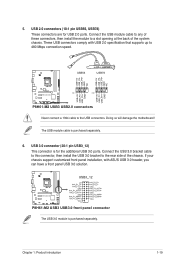
...GND NC USB+5V USB_P6USB_P6+ GND NC USB+5V USB_P7USB_P7+ GND USB+5V USB_P5USB_P5+ GND P8H61-M2 USB3 PIN 1 PIN 1 P8H61-M2 USB3 USB2.0 connectors Never connect a 1394 cable to 480 Mbps connection speed. The USB module cable is for USB 2.0 ports. 5.... to a slot opening at the back of the chassis. Chapter 1: Product introduction 1-19 USB3_12 P8H61-M2 USB3 P8H61-M2 USB3 USB3.0 front panel connector The USB 3.0 module is purchased separately. These USB connectors comply with ASUS USB 3.0 header, you can have a front panel USB 3.0 solution. If your chassis support customized...
...GND NC USB+5V USB_P6USB_P6+ GND NC USB+5V USB_P7USB_P7+ GND USB+5V USB_P5USB_P5+ GND P8H61-M2 USB3 PIN 1 PIN 1 P8H61-M2 USB3 USB2.0 connectors Never connect a 1394 cable to 480 Mbps connection speed. The USB module cable is for USB 2.0 ports. 5.... to a slot opening at the back of the chassis. Chapter 1: Product introduction 1-19 USB3_12 P8H61-M2 USB3 P8H61-M2 USB3 USB3.0 front panel connector The USB 3.0 module is purchased separately. These USB connectors comply with ASUS USB 3.0 header, you can have a front panel USB 3.0 solution. If your chassis support customized...
User Manual
Page 30
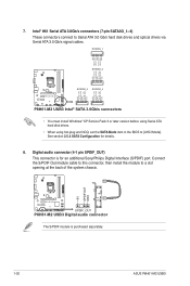
... install the module to a slot opening at the back of the system chassis. +5V SPDIFOUT GND P8H61-M2 USB3 SPDIF_OUT P8H61-M2 USB3 Digital audio connector The S/PDIF module is for details. 8. Digital audio connector (4-1 pin SPDIF_OUT) This connector is purchased separately. 1-20 ASUS P8H61-M2 USB3 SATA3G_1 GND RSATA_TXP1 RSATA_TXN1 GND RSATA_RXN1 RSATA_RXP1 GND SATA3G_2 GND RSATA_RXP2 RSATA_RXN2 GND RSATA_TXN2 RSATA_TXP2 GND...
... install the module to a slot opening at the back of the system chassis. +5V SPDIFOUT GND P8H61-M2 USB3 SPDIF_OUT P8H61-M2 USB3 Digital audio connector The S/PDIF module is for details. 8. Digital audio connector (4-1 pin SPDIF_OUT) This connector is purchased separately. 1-20 ASUS P8H61-M2 USB3 SATA3G_1 GND RSATA_TXP1 RSATA_TXN1 GND RSATA_RXN1 RSATA_RXP1 GND SATA3G_2 GND RSATA_RXP2 RSATA_RXN2 GND RSATA_TXN2 RSATA_TXP2 GND...

User Manual
Page 31
... system power LED. Ground Reset 9. Connect the chassis power LED cable to this connector. Connect the HDD Activity LED cable to this connector. F_PANEL PLED PWRBTN PIN 1 P8H61-M2 USB3 +HDLED RESET P8H61-M2 USB3 System panel connector • System power LED (2-pin PLED) This 2-pin connector is read from or written to hear system beeps and warnings. The IDE...
... system power LED. Ground Reset 9. Connect the chassis power LED cable to this connector. Connect the HDD Activity LED cable to this connector. F_PANEL PLED PWRBTN PIN 1 P8H61-M2 USB3 +HDLED RESET P8H61-M2 USB3 System panel connector • System power LED (2-pin PLED) This 2-pin connector is read from or written to hear system beeps and warnings. The IDE...

User Manual
Page 51
...on the audio standard that the front panel audio module supports. [HD] Sets the front panel audio connector (AAFP) mode to high definition audio. [AC97] Sets the front panel audio connector (AAFP) mode to legacy AC'97. If detected, the USB controller legacy mode is disabled. EHCI...previous item to [Enabled] and allows you to set the HD Audio Controller item to detect the presence of the Realtek LAN controller. Legacy USB3.0 Support [Enabled] [Enabled] Enables the support for operating systems without an EHCI hand‑off feature. [Disabled] Disables the function. 2.5.6...
...on the audio standard that the front panel audio module supports. [HD] Sets the front panel audio connector (AAFP) mode to high definition audio. [AC97] Sets the front panel audio connector (AAFP) mode to legacy AC'97. If detected, the USB controller legacy mode is disabled. EHCI...previous item to [Enabled] and allows you to set the HD Audio Controller item to detect the presence of the Realtek LAN controller. Legacy USB3.0 Support [Enabled] [Enabled] Enables the support for operating systems without an EHCI hand‑off feature. [Disabled] Disables the function. 2.5.6...


