
P8H61-M PLUS V3 User's Manual
Page 1
Motherboard P8H61-M PLUS V3
Motherboard P8H61-M PLUS V3

P8H61-M PLUS V3 User's Manual
Page 3
Contents Safety information vi About this guide vii P8H61-M PLUS V3 specifications summary ix Chapter 1 Product introduction 1.1 Before you proceed 1-1 1.2 Motherboard overview 1-2 1.2.1 Placement direction 1-2 1.2.2 Screw holes 1-2 1.2.3 Motherboard layout 1-3 1.2.4 Layout contents 1-3 1.3 Central Processing Unit (CPU 1-4 1.3.1 Installing the CPU 1-4 1.3.2 Installing the CPU heatsink and fan 1-7 1.3.3 Uninstalling the CPU heatsink and fan 1-8 1.4 System memory 1-9 1.4.1 Overview 1-9 1.4.2 ...
Contents Safety information vi About this guide vii P8H61-M PLUS V3 specifications summary ix Chapter 1 Product introduction 1.1 Before you proceed 1-1 1.2 Motherboard overview 1-2 1.2.1 Placement direction 1-2 1.2.2 Screw holes 1-2 1.2.3 Motherboard layout 1-3 1.2.4 Layout contents 1-3 1.3 Central Processing Unit (CPU 1-4 1.3.1 Installing the CPU 1-4 1.3.2 Installing the CPU heatsink and fan 1-7 1.3.3 Uninstalling the CPU heatsink and fan 1-8 1.4 System memory 1-9 1.4.1 Overview 1-9 1.4.2 ...

P8H61-M PLUS V3 User's Manual
Page 6
...qualified service technician or your dealer immediately. • To avoid short circuits, keep paper clips, screws, and staples away from the motherboard, ensure that all cables are correctly connected and the power cables are not damaged. These devices could interrupt the grounding circuit. &#...8226; If the power supply is set to the correct voltage in any damage, contact your retailer. Operation safety • Before installing the motherboard and adding devices on a stable surface. • If you add a device. • Before connecting or removing signal cables from connectors,...
...qualified service technician or your dealer immediately. • To avoid short circuits, keep paper clips, screws, and staples away from the motherboard, ensure that all cables are correctly connected and the power cables are not damaged. These devices could interrupt the grounding circuit. &#...8226; If the power supply is set to the correct voltage in any damage, contact your retailer. Operation safety • Before installing the motherboard and adding devices on a stable surface. • If you add a device. • Before connecting or removing signal cables from connectors,...

P8H61-M PLUS V3 User's Manual
Page 7
... of the BIOS parameters are not part of the motherboard and the new technology it supports. • Chapter 2: BIOS information This chapter tells how to change system settings through the BIOS Setup menus. ASUS websites The ASUS website provides updated information on ASUS hardware and software products. Refer to the following parts..., such as warranty flyers, that may have been added by your dealer. vii Where to find more information Refer to the ASUS contact information. 2. How this guide This user guide contains the information you need when installing and configuring the...
... of the BIOS parameters are not part of the motherboard and the new technology it supports. • Chapter 2: BIOS information This chapter tells how to change system settings through the BIOS Setup menus. ASUS websites The ASUS website provides updated information on ASUS hardware and software products. Refer to the following parts..., such as warranty flyers, that may have been added by your dealer. vii Where to find more information Refer to the ASUS contact information. 2. How this guide This user guide contains the information you need when installing and configuring the...
P8H61-M PLUS V3 User's Manual
Page 11
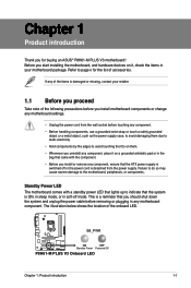
... the edges to page x for buying an ASUS® P8H61-M PLUS V3 motherboard! SB_PWR P8H61-M PLUS V3 ON OFF Standby Power Powered Off P8H61-M PLUS V3 Onboard LED Chapter 1: Product introduction 1-1 If any of the following precautions before you install motherboard components or change any motherboard settings. • Unplug the power cord from...check the items in your retailer. 1.1 Before you proceed Take note of the items is damaged or missing, contact your motherboard package. Refer to avoid touching the ICs on a grounded antistatic pad or in the bag that came with a standby ...
... the edges to page x for buying an ASUS® P8H61-M PLUS V3 motherboard! SB_PWR P8H61-M PLUS V3 ON OFF Standby Power Powered Off P8H61-M PLUS V3 Onboard LED Chapter 1: Product introduction 1-1 If any of the following precautions before you install motherboard components or change any motherboard settings. • Unplug the power cord from...check the items in your retailer. 1.1 Before you proceed Take note of the items is damaged or missing, contact your motherboard package. Refer to avoid touching the ICs on a grounded antistatic pad or in the bag that came with a standby ...
P8H61-M PLUS V3 User's Manual
Page 12
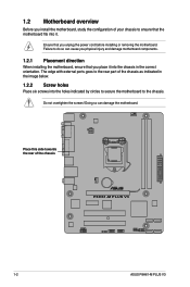
... power cord before installing or removing the motherboard. Failure to do so can damage the motherboard. Ensure that you place it . Place this side towards the rear of the chassis P8H61-M PLUS V3 1-2 ASUS P8H61-M PLUS V3 1.2 Motherboard overview Before you install the motherboard, study the configuration of your chassis to ensure that the motherboard fits into it into the holes indicated...
... power cord before installing or removing the motherboard. Failure to do so can damage the motherboard. Ensure that you place it . Place this side towards the rear of the chassis P8H61-M PLUS V3 1-2 ASUS P8H61-M PLUS V3 1.2 Motherboard overview Before you install the motherboard, study the configuration of your chassis to ensure that the motherboard fits into it into the holes indicated...

P8H61-M PLUS V3 User's Manual
Page 13
...-1 pin AAFP) 1-17 1-20 12. 1.2.3 Motherboard layout 1 2 3 1 4 19.8cm(7.8in) KBMS EPU CPU_FAN COM ATX12V DDR3 DIMM_A1 (64bit, 240-pin module) DDR3 DIMM_B1 (64bit, 240-pin module) EATXPWR 24.4cm(9.6in) LPT VGA LGA1155 USB34 2 LAN1_USB12 AUDIO RTL 8111E Lithium Cell CMOS Power CHA_FAN PCIEX16 P8H61-M PLUS V3 Super I/O PCIEX1_1 ASM 1083 PCI1 64Mb...
...-1 pin AAFP) 1-17 1-20 12. 1.2.3 Motherboard layout 1 2 3 1 4 19.8cm(7.8in) KBMS EPU CPU_FAN COM ATX12V DDR3 DIMM_A1 (64bit, 240-pin module) DDR3 DIMM_B1 (64bit, 240-pin module) EATXPWR 24.4cm(9.6in) LPT VGA LGA1155 USB34 2 LAN1_USB12 AUDIO RTL 8111E Lithium Cell CMOS Power CHA_FAN PCIEX16 P8H61-M PLUS V3 Super I/O PCIEX1_1 ASM 1083 PCI1 64Mb...
P8H61-M PLUS V3 User's Manual
Page 14
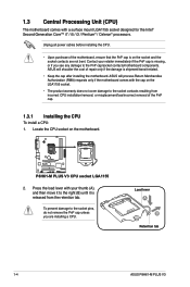
...ASUS P8H61-M PLUS V3 ASUS will process Return Merchandise Authorization (RMA) requests only if the motherboard comes with the cap on the LGA1155 socket. • The product warranty does not cover damage to the socket contacts resulting from the retention tab. ASUS will shoulder the cost of the motherboard...of the PnP cap. 1.3.1 Installing the CPU To install a CPU: 1. P8H61-M PLUS V3 P8H61-M PLUS V3 CPU socket LGA1155 2. Contact your thumb (A), and then move it to the PnP cap/socket contacts/motherboard components. Locate the CPU socket on the socket and the socket contacts are...
...ASUS P8H61-M PLUS V3 ASUS will process Return Merchandise Authorization (RMA) requests only if the motherboard comes with the cap on the LGA1155 socket. • The product warranty does not cover damage to the socket contacts resulting from the retention tab. ASUS will shoulder the cost of the motherboard...of the PnP cap. 1.3.1 Installing the CPU To install a CPU: 1. P8H61-M PLUS V3 P8H61-M PLUS V3 CPU socket LGA1155 2. Contact your thumb (A), and then move it to the PnP cap/socket contacts/motherboard components. Locate the CPU socket on the socket and the socket contacts are...

P8H61-M PLUS V3 User's Manual
Page 17
... sockets in size and dimension. If you install the CPU fan and heatsink assembly. Place the heatsink on the motherboard. A B 1 1 B A The type of the installed CPU, ensuring that you have installed the motherboard to the chassis before you install the heatsink and fan assembly. If you buy a CPU separately, ensure that you...
... sockets in size and dimension. If you install the CPU fan and heatsink assembly. Place the heatsink on the motherboard. A B 1 1 B A The type of the installed CPU, ensuring that you have installed the motherboard to the chassis before you install the heatsink and fan assembly. If you buy a CPU separately, ensure that you...

P8H61-M PLUS V3 User's Manual
Page 18
CPU_FAN CPU FAN PWM CPU FAN IN CPU FAN PWR GND P8H61-M PLUS V3 P8H61-M PLUS V3 CPU fan connector Do not forget to disengage the heatsink and fan assembly from the connector on the motherboard labeled CPU_FAN. A B A B B A B A 1-8 ASUS P8H61-M PLUS V3 Disconnect the CPU fan cable from the motherboard. Pull up two fasteners at a time in a diagonal sequence to connect the CPU...
CPU_FAN CPU FAN PWM CPU FAN IN CPU FAN PWR GND P8H61-M PLUS V3 P8H61-M PLUS V3 CPU fan connector Do not forget to disengage the heatsink and fan assembly from the connector on the motherboard labeled CPU_FAN. A B A B B A B A 1-8 ASUS P8H61-M PLUS V3 Disconnect the CPU fan cable from the motherboard. Pull up two fasteners at a time in a diagonal sequence to connect the CPU...

P8H61-M PLUS V3 User's Manual
Page 19
... DIMM_B1 P8H61-M PLUS V3 Channel Channel A Channel B Sockets DIMM_A1 DIMM_B1 P8H61-M PLUS V3 240-pin DDR3 DIMM sockets Chapter 1: Product introduction 1-9 Rotate each fastener clockwise to prevent installation on a DDR2 DIMM socket. A DDR3 module has the same physical dimensions as a DDR2 DIMM but is notched differently to ensure correct orientation when reinstalling. 1.4 System memory 1.4.1 Overview The motherboard...
... DIMM_B1 P8H61-M PLUS V3 Channel Channel A Channel B Sockets DIMM_A1 DIMM_B1 P8H61-M PLUS V3 240-pin DDR3 DIMM sockets Chapter 1: Product introduction 1-9 Rotate each fastener clockwise to prevent installation on a DDR2 DIMM socket. A DDR3 module has the same physical dimensions as a DDR2 DIMM but is notched differently to ensure correct orientation when reinstalling. 1.4 System memory 1.4.1 Overview The motherboard...

P8H61-M PLUS V3 User's Manual
Page 20
... x 2GB) DS Chip Brand Chip NO. - - DIMM socket support Voltage (optional) 1 DIMM 2 DIMMs 1.65V • • 1-10 ASUS P8H61-M PLUS V3 For optimum compatibility, we recommend that you obtain memory modules from the same vendor. • Due to support a full memory load (2 DIMMs) or... than the vendor-marked value. Size SS/DS KINGSTON KHX2250C9D3T1K2/4GX(XMP) 4GB(2 x 2GB) DS Chip Brand Chip NO. - - P8H61-M PLUS V3 Motherboard Qualified Vendors Lists (QVL) DDR3-2666 (O.C.) MHz capability Vendors Part No. 1.4.2 Memory configurations You may install 512MB, 1GB, 2GB, and...
... x 2GB) DS Chip Brand Chip NO. - - DIMM socket support Voltage (optional) 1 DIMM 2 DIMMs 1.65V • • 1-10 ASUS P8H61-M PLUS V3 For optimum compatibility, we recommend that you obtain memory modules from the same vendor. • Due to support a full memory load (2 DIMMs) or... than the vendor-marked value. Size SS/DS KINGSTON KHX2250C9D3T1K2/4GX(XMP) 4GB(2 x 2GB) DS Chip Brand Chip NO. - - P8H61-M PLUS V3 Motherboard Qualified Vendors Lists (QVL) DDR3-2666 (O.C.) MHz capability Vendors Part No. 1.4.2 Memory configurations You may install 512MB, 1GB, 2GB, and...

P8H61-M PLUS V3 User's Manual
Page 23
... DIMMs or other system components. Remove the DIMM from the socket. DIMM notch Chapter 1: Product introduction 1-13 Press the retaining clips outward to both the motherboard and the components. 1. Simultaneously press the retaining clips outward to avoid damaging the DIMM. 3. Firmly insert the DIMM into a socket in the wrong direction to...
... DIMMs or other system components. Remove the DIMM from the socket. DIMM notch Chapter 1: Product introduction 1-13 Press the retaining clips outward to both the motherboard and the components. 1. Simultaneously press the retaining clips outward to avoid damaging the DIMM. 3. Firmly insert the DIMM into a socket in the wrong direction to...

P8H61-M PLUS V3 User's Manual
Page 24
...that supports PCI Express x16 3.0/2.0 graphic cards complying with the PCI Express specifications. 1-14 ASUS P8H61-M PLUS V3 Failure to the chassis with the PCI Express specifications. 1.5.5 PCI Express x16 slot This motherboard has a PCI Express 3.0/2.0 x16 slot that they support. Keep the screw for the ...already installed in a chassis). 3. Unplug the power cord before adding or removing expansion cards. Remove the system unit cover (if your motherboard is completely seated on shared slots, ensure that the drivers support "Share IRQ" or that you intend to use . 4. 1.5 Expansion ...
...that supports PCI Express x16 3.0/2.0 graphic cards complying with the PCI Express specifications. 1-14 ASUS P8H61-M PLUS V3 Failure to the chassis with the PCI Express specifications. 1.5.5 PCI Express x16 slot This motherboard has a PCI Express 3.0/2.0 x16 slot that they support. Keep the screw for the ...already installed in a chassis). 3. Unplug the power cord before adding or removing expansion cards. Remove the system unit cover (if your motherboard is completely seated on shared slots, ensure that the drivers support "Share IRQ" or that you intend to use . 4. 1.5 Expansion ...

P8H61-M PLUS V3 User's Manual
Page 27
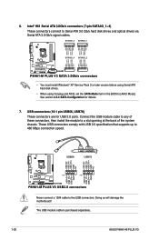
...AAFP PIN 1 MIC2 MICPWR Line out_R NC Line out_L PORT1 L PORT1 R PORT2 R SENSE_SEND PORT2 L P8H61-M PLUS V3 HD-audio-compliant Legacy AC'97 pin definition compliant definition P8H61-M PLUS V3 Front panel audio connector • We recommend that supports either HD Audio or legacy AC`97 audio standard....front panel audio module to [AC97]. These four 4-pin Universal Serial Bus (USB) ports are for details. Connect one end of the motherboard's high-definition audio capability. • If you connect a high-definition front panel audio module to this connector to [HD]. PS/2 ...
...AAFP PIN 1 MIC2 MICPWR Line out_R NC Line out_L PORT1 L PORT1 R PORT2 R SENSE_SEND PORT2 L P8H61-M PLUS V3 HD-audio-compliant Legacy AC'97 pin definition compliant definition P8H61-M PLUS V3 Front panel audio connector • We recommend that supports either HD Audio or legacy AC`97 audio standard....front panel audio module to [AC97]. These four 4-pin Universal Serial Bus (USB) ports are for details. Connect one end of the motherboard's high-definition audio capability. • If you connect a high-definition front panel audio module to this connector to [HD]. PS/2 ...

P8H61-M PLUS V3 User's Manual
Page 29
... to a slot opening at the back of the system chassis. +5V SPDIFOUT GND P8H61-M PLUS V3 SPDIF_OUT P8H61-M PLUS V3 Digital audio connector The S/PDIF module is for an additional Sony/Philips Digital Interface (S/PDIF) port. Do not place jumper caps on the motherboard, ensuring that the black wire of each cable matches the ground pin of...
... to a slot opening at the back of the system chassis. +5V SPDIFOUT GND P8H61-M PLUS V3 SPDIF_OUT P8H61-M PLUS V3 Digital audio connector The S/PDIF module is for an additional Sony/Philips Digital Interface (S/PDIF) port. Do not place jumper caps on the motherboard, ensuring that the black wire of each cable matches the ground pin of...
P8H61-M PLUS V3 User's Manual
Page 30
...system chassis. The USB module cable is purchased separately. 1-20 ASUS P8H61-M PLUS V3 These USB connectors comply with USB 2.0 specification that supports up ...motherboard! Intel® H61 Serial ATA 3.0Gb/s connectors (7-pin SATA3G_1~4) These connectors connect to the USB connectors. 6. SATA3G_3 SATA3G_1 GND RSATA_TXP3 RSATA_TXN3 GND RSATA_RXN3 RSATA_RXP3 GND GND RSATA_TXP1 RSATA_TXN1 GND RSATA_RXN1 RSATA_RXP1 GND GND RSATA_RXP4 RSATA_RXN4 GND RSATA_TXN4 RSATA_TXP4 GND GND RSATA_RXP2 RSATA_RXN2 GND RSATA_TXN2 RSATA_TXP2 GND P8H61-M PLUS V3 SATA3G_4 SATA3G_2 P8H61-M PLUS V3...
...system chassis. The USB module cable is purchased separately. 1-20 ASUS P8H61-M PLUS V3 These USB connectors comply with USB 2.0 specification that supports up ...motherboard! Intel® H61 Serial ATA 3.0Gb/s connectors (7-pin SATA3G_1~4) These connectors connect to the USB connectors. 6. SATA3G_3 SATA3G_1 GND RSATA_TXP3 RSATA_TXN3 GND RSATA_RXN3 RSATA_RXP3 GND GND RSATA_TXP1 RSATA_TXN1 GND RSATA_RXN1 RSATA_RXP1 GND GND RSATA_RXP4 RSATA_RXN4 GND RSATA_TXN4 RSATA_TXP4 GND GND RSATA_RXP2 RSATA_RXN2 GND RSATA_TXN2 RSATA_TXP2 GND P8H61-M PLUS V3 SATA3G_4 SATA3G_2 P8H61-M PLUS V3...

P8H61-M PLUS V3 User's Manual
Page 32
... stability. 1.8.2 Support DVD information The Support DVD that comes with the motherboard package contains the drivers, software applications, and utilities that you can install to change at www.asus.com for reference only. Double-click the ASSETUP.EXE to maximize the ... an item to install If Autorun is NOT enabled in your computer, browse the contents of ASUS motherboard. Always install the latest OS version and corresponding updates to run the Support DVD Place the ... features of the Support DVD to display their respective menus. To run the DVD. 1-22 ASUS P8H61-M PLUS V3
... stability. 1.8.2 Support DVD information The Support DVD that comes with the motherboard package contains the drivers, software applications, and utilities that you can install to change at www.asus.com for reference only. Double-click the ASSETUP.EXE to maximize the ... an item to install If Autorun is NOT enabled in your computer, browse the contents of ASUS motherboard. Always install the latest OS version and corresponding updates to run the Support DVD Place the ... features of the Support DVD to display their respective menus. To run the DVD. 1-22 ASUS P8H61-M PLUS V3
P8H61-M PLUS V3 User's Manual
Page 33
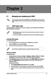
...appears. 2. Installing ASUS Update To install ASUS Update: 1. Quit all Windows® applications before you update the BIOS using the ASUS Update utility. 2.1.1 ASUS Update utility The ASUS Update is available in the support DVD that you wish to manage, save, and update the motherboard BIOS in Windows®...; environment. • ASUS Update requires an Internet connection either of the original motherboard BIOS file to a USB flash disk in case you need to avoid network ...
...appears. 2. Installing ASUS Update To install ASUS Update: 1. Quit all Windows® applications before you update the BIOS using the ASUS Update utility. 2.1.1 ASUS Update utility The ASUS Update is available in the support DVD that you wish to manage, save, and update the motherboard BIOS in Windows®...; environment. • ASUS Update requires an Internet connection either of the original motherboard BIOS file to a USB flash disk in case you need to avoid network ...

P8H61-M PLUS V3 User's Manual
Page 35
... ensure system compatibility and stability, we recommend that you to load default BIOS values. Doing so can restore a corrupted BIOS file using the motherboard support DVD or a USB flash drive that allows you press to restore the BIOS file when it fails or gets corrupted during the updating ...to enter BIOS Setup to the Drive field. 4. Download the latest BIOS file from the ASUS website at www.asus.com. Insert the support DVD to prevent system boot failure! 2.1.3 ASUS CrashFree BIOS 3 utility The ASUS CrashFree BIOS 3 is done. • This function supports USB flash disks with FAT 32...
... ensure system compatibility and stability, we recommend that you to load default BIOS values. Doing so can restore a corrupted BIOS file using the motherboard support DVD or a USB flash drive that allows you press to restore the BIOS file when it fails or gets corrupted during the updating ...to enter BIOS Setup to the Drive field. 4. Download the latest BIOS file from the ASUS website at www.asus.com. Insert the support DVD to prevent system boot failure! 2.1.3 ASUS CrashFree BIOS 3 utility The ASUS CrashFree BIOS 3 is done. • This function supports USB flash disks with FAT 32...


