
User Manual
Page 1
Motherboard P8H61-M PLUS V2
Motherboard P8H61-M PLUS V2
User Manual
Page 3
Contents Notices...vi Safety information vii About this guide viii P8H61-M PLUS V2 specifications summary ix Chapter 1: Product introduction 1.1 Before you proceed 1-1 1.2 Motherboard overview 1-2 1.2.1 Placement direction 1-2 1.2.2 Screw holes 1-2 1.2.3 Motherboard layout 1-3 1.2.4 Layout contents 1-3 1.3 Central Processing Unit (CPU 1-4 1.3.1 Installing the CPU 1-4 1.3.2 Installing the CPU heatsink and fan 1-7 1.3.3 Uninstalling the CPU heatsink and fan 1-8 1.4 System memory 1-9 1.4.1 Overview 1-9 1.4.2 ...
Contents Notices...vi Safety information vii About this guide viii P8H61-M PLUS V2 specifications summary ix Chapter 1: Product introduction 1.1 Before you proceed 1-1 1.2 Motherboard overview 1-2 1.2.1 Placement direction 1-2 1.2.2 Screw holes 1-2 1.2.3 Motherboard layout 1-3 1.2.4 Layout contents 1-3 1.3 Central Processing Unit (CPU 1-4 1.3.1 Installing the CPU 1-4 1.3.2 Installing the CPU heatsink and fan 1-7 1.3.3 Uninstalling the CPU heatsink and fan 1-8 1.4 System memory 1-9 1.4.1 Overview 1-9 1.4.2 ...
User Manual
Page 7
...of the crossed out wheeled bin indicates that the battery should not be placed in municipal waste. Operation safety • Before installing the motherboard and adding devices on a stable surface. • If you detect any area where it may become wet. • Place the ... Authorisation, and Restriction of Chemicals) regulatory framework, we published the chemical substances in our products at ASUS REACH website at http://csr.asus.com/english/index.aspx DO NOT throw the motherboard in municipal waste. REACH Complying with the package. • Before using the product, ensure that ...
...of the crossed out wheeled bin indicates that the battery should not be placed in municipal waste. Operation safety • Before installing the motherboard and adding devices on a stable surface. • If you detect any area where it may become wet. • Place the ... Authorisation, and Restriction of Chemicals) regulatory framework, we published the chemical substances in our products at ASUS REACH website at http://csr.asus.com/english/index.aspx DO NOT throw the motherboard in municipal waste. REACH Complying with the package. • Before using the product, ensure that ...
User Manual
Page 8
... to complete a task. Example: means that you must press the enclosed key. Detailed descriptions of the BIOS parameters are linked with a plus sign (+). CAUTION: Information to prevent damage to the components when trying to emphasize a word or a phrase. IMPORTANT: Instructions that you... guide To ensure that you MUST follow to the ASUS contact information. 2. About this guide is organized This guide contains the following parts: • Chapter 1: Product introduction This chapter describes the features of the motherboard and the new technology it supports. • Chapter...
... to complete a task. Example: means that you must press the enclosed key. Detailed descriptions of the BIOS parameters are linked with a plus sign (+). CAUTION: Information to prevent damage to the components when trying to emphasize a word or a phrase. IMPORTANT: Instructions that you... guide To ensure that you MUST follow to the ASUS contact information. 2. About this guide is organized This guide contains the following parts: • Chapter 1: Product introduction This chapter describes the features of the motherboard and the new technology it supports. • Chapter...

User Manual
Page 11
... location of the onboard LED. Failure to do so may cause severe damage to page x for buying an ASUS® P8H61-M PLUS V2 motherboard! This is damaged or missing, contact your motherboard package. Before you start installing the motherboard, and hardware devices on a grounded antistatic pad or in the bag that came with a standby power LED that...
... location of the onboard LED. Failure to do so may cause severe damage to page x for buying an ASUS® P8H61-M PLUS V2 motherboard! This is damaged or missing, contact your motherboard package. Before you start installing the motherboard, and hardware devices on a grounded antistatic pad or in the bag that came with a standby power LED that...

User Manual
Page 12
... configuration of your chassis to ensure that you place it into it. The edge with external ports goes to the rear part of the chassis P8H61-M PLUS V2 1-2 ASUS P8H61-M PLUS V2 Ensure that the motherboard fits into the chassis in the image below. 1.2.2 Screw holes Place six screws into the holes indicated by circles to secure the...
... configuration of your chassis to ensure that you place it into it. The edge with external ports goes to the rear part of the chassis P8H61-M PLUS V2 1-2 ASUS P8H61-M PLUS V2 Ensure that the motherboard fits into the chassis in the image below. 1.2.2 Screw holes Place six screws into the holes indicated by circles to secure the...

User Manual
Page 14
... PnP cap/socket contacts/motherboard components. Load lever A B Retention tab 1-4 ASUS P8H61-M PLUS V2 Unplug all power cables before installing the CPU. • Upon purchase of repair only if the damage is on the motherboard. Locate the CPU socket on the socket and the socket contacts are installing a CPU. P8H61-M PLUS V2 P8H61-M PLUS V2 CPU socket LGA1155 2. ASUS will shoulder the cost...
... PnP cap/socket contacts/motherboard components. Load lever A B Retention tab 1-4 ASUS P8H61-M PLUS V2 Unplug all power cables before installing the CPU. • Upon purchase of repair only if the damage is on the motherboard. Locate the CPU socket on the socket and the socket contacts are installing a CPU. P8H61-M PLUS V2 P8H61-M PLUS V2 CPU socket LGA1155 2. ASUS will shoulder the cost...
User Manual
Page 17
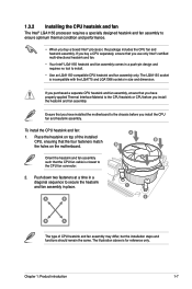
... and dimension. If you purchased a separate CPU heatsink and fan assembly, ensure that you have installed the motherboard to the chassis before you install the heatsink and fan assembly. Place the heatsink on the motherboard. Ensure that you have properly applied Thermal Interface Material to the CPU heatsink or CPU before you...
... and dimension. If you purchased a separate CPU heatsink and fan assembly, ensure that you have installed the motherboard to the chassis before you install the heatsink and fan assembly. Place the heatsink on the motherboard. Ensure that you have properly applied Thermal Interface Material to the CPU heatsink or CPU before you...

User Manual
Page 18
... PWM CPU FAN IN CPU FAN PWR GND P8H61-M PLUS V2 P8H61-M PLUS V2 CPU fan connector Do not forget to plug this connector. 1.3.3 Uninstalling the CPU heatsink and fan To uninstall the CPU heatsink and fan: 1. A B A B B A B A 1-8 ASUS P8H61-M PLUS V2 Connect the CPU fan cable to disengage the heatsink and fan assembly from the connector on the motherboard labeled CPU_FAN.
... PWM CPU FAN IN CPU FAN PWR GND P8H61-M PLUS V2 P8H61-M PLUS V2 CPU fan connector Do not forget to plug this connector. 1.3.3 Uninstalling the CPU heatsink and fan To uninstall the CPU heatsink and fan: 1. A B A B B A B A 1-8 ASUS P8H61-M PLUS V2 Connect the CPU fan cable to disengage the heatsink and fan assembly from the connector on the motherboard labeled CPU_FAN.
User Manual
Page 19
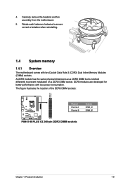
... DIMM sockets: DIMM_A1 DIMM_B1 P8H61-M PLUS V2 Channel Channel A Channel B Sockets DIMM_A1 DIMM_B1 P8H61-M PLUS V2 240-pin DDR3 DIMM sockets Chapter 1: Product introduction 1-9 4. DDR3 modules are developed for better performance with two Double Data Rate 3 (DDR3) Dual Inline Memory Modules (DIMM) sockets. Carefully remove the heatsink and fan assembly from the motherboard. 5. A DDR3 module has the...
... DIMM sockets: DIMM_A1 DIMM_B1 P8H61-M PLUS V2 Channel Channel A Channel B Sockets DIMM_A1 DIMM_B1 P8H61-M PLUS V2 240-pin DDR3 DIMM sockets Chapter 1: Product introduction 1-9 4. DDR3 modules are developed for better performance with two Double Data Rate 3 (DDR3) Dual Inline Memory Modules (DIMM) sockets. Carefully remove the heatsink and fan assembly from the motherboard. 5. A DDR3 module has the...

User Manual
Page 20
...- • • Kingtiger 2GB DIMM PC3-8500 2GB DS Hynix H5TQ1G83AFP G7C - - • • 1-10 ASUS P8H61-M PLUS V2 The system maps the total size of the following: - P8H61-M PLUS V2 Motherboard Qualified Vendors Lists (QVL) DDR3-1066 MHz capability Vendors Part No. 1.4.2 Memory configurations You may install 512MB, 1GB, 2GB...8226; Always install DIMMs with 8GB or above DIMMs. ASUS will update the memory QVL once the DIMMs are using a 32-bit Windows® OS. - For effective use a more on the motherboard. • This motherboard does not support DIMMs made up of memory, we...
...- • • Kingtiger 2GB DIMM PC3-8500 2GB DS Hynix H5TQ1G83AFP G7C - - • • 1-10 ASUS P8H61-M PLUS V2 The system maps the total size of the following: - P8H61-M PLUS V2 Motherboard Qualified Vendors Lists (QVL) DDR3-1066 MHz capability Vendors Part No. 1.4.2 Memory configurations You may install 512MB, 1GB, 2GB...8226; Always install DIMMs with 8GB or above DIMMs. ASUS will update the memory QVL once the DIMMs are using a 32-bit Windows® OS. - For effective use a more on the motherboard. • This motherboard does not support DIMMs made up of memory, we...
User Manual
Page 23
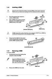
... keyed with a notch so that it flips out with your fingers when pressing the retaining 1 clips. Simultaneously press the retaining clips outward to both the motherboard and the components. 1. DIMM notch Chapter 1: Product introduction 1-13 Locked Retaining Clip 1.4.4 Removing a DIMM To remove a DIMM: 1. Failure to do so can cause severe damage...
... keyed with a notch so that it flips out with your fingers when pressing the retaining 1 clips. Simultaneously press the retaining clips outward to both the motherboard and the components. 1. DIMM notch Chapter 1: Product introduction 1-13 Locked Retaining Clip 1.4.4 Removing a DIMM To remove a DIMM: 1. Failure to do so can cause severe damage...

User Manual
Page 24
Failure to do not need to the chassis with the PCI Express specifications. 1-14 ASUS P8H61-M PLUS V2 Remove the system unit cover (if your motherboard is completely seated on BIOS setup. 2. Align the card connector with the slot and press firmly until the card ...Chapter 2 for later use . Install the software drivers for the card. 2. 1.5 Expansion slots In the future, you physical injury and damage motherboard components. 1.5.1 Installing an expansion card To install an expansion card: 1. Unplug the power cord before adding or removing expansion cards. Before installing the...
Failure to do not need to the chassis with the PCI Express specifications. 1-14 ASUS P8H61-M PLUS V2 Remove the system unit cover (if your motherboard is completely seated on BIOS setup. 2. Align the card connector with the slot and press firmly until the card ...Chapter 2 for later use . Install the software drivers for the card. 2. 1.5 Expansion slots In the future, you physical injury and damage motherboard components. 1.5.1 Installing an expansion card To install an expansion card: 1. Unplug the power cord before adding or removing expansion cards. Before installing the...
User Manual
Page 27
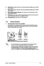
...motherboard's high-definition audio capability. • If you want to connect a high-definition front panel audio module to this connector, set the item to [HD]. GND PRESENCE# SENSE1_RETUR SENSE2_RETUR AGND NC NC NC AAFP PIN 1 PIN 1 MIC2 MICPWR Line out_R NC Line out_L PORT1 L PORT1 R PORT2 R SENSE_SEND PORT2 L P8H61-M PLUS V2... HD-audio-compliant Legacy AC'97 pin definition compliant definition P8H61-M PLUS V2 Front panel audio connector • We recommend that supports either HD Audio or ...
...motherboard's high-definition audio capability. • If you want to connect a high-definition front panel audio module to this connector, set the item to [HD]. GND PRESENCE# SENSE1_RETUR SENSE2_RETUR AGND NC NC NC AAFP PIN 1 PIN 1 MIC2 MICPWR Line out_R NC Line out_L PORT1 L PORT1 R PORT2 R SENSE_SEND PORT2 L P8H61-M PLUS V2... HD-audio-compliant Legacy AC'97 pin definition compliant definition P8H61-M PLUS V2 Front panel audio connector • We recommend that supports either HD Audio or ...
User Manual
Page 29
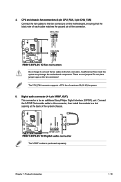
... air flow inside the system may damage the motherboard components. The CPU_FAN connector supports a CPU fan of the connector. CPU_FAN CPU FAN PWM CPU FAN IN CPU FAN PWR GND P8H61-M PLUS V2 CHA_FAN Rotation +12V GND P8H61-M PLUS V2 fan connectors Do not forget to connect the ...the system chassis. +5V SPDIFOUT GND P8H61-M PLUS V2 SPDIF_OUT P8H61-M PLUS V2 Digital audio connector The S/PDIF module is for an additional Sony/Philips Digital Interface (S/PDIF) port. Chapter 1: Product introduction 1-19 4. Do not place jumper caps on the motherboard, ensuring that the black wire of...
... air flow inside the system may damage the motherboard components. The CPU_FAN connector supports a CPU fan of the connector. CPU_FAN CPU FAN PWM CPU FAN IN CPU FAN PWR GND P8H61-M PLUS V2 CHA_FAN Rotation +12V GND P8H61-M PLUS V2 fan connectors Do not forget to connect the ...the system chassis. +5V SPDIFOUT GND P8H61-M PLUS V2 SPDIF_OUT P8H61-M PLUS V2 Digital audio connector The S/PDIF module is for an additional Sony/Philips Digital Interface (S/PDIF) port. Chapter 1: Product introduction 1-19 4. Do not place jumper caps on the motherboard, ensuring that the black wire of...

User Manual
Page 30
...-plug and NCQ, set the SATA Mode item in the BIOS to 480 Mbps connection speed. Doing so will damage the motherboard! 6. The USB module cable is purchased separately. 1-20 ASUS P8H61-M PLUS V2 USB connectors (10-1 pin USB78, USB910) These connectors are for details. 7. These USB connectors comply with USB 2.0 specification that supports up...
...-plug and NCQ, set the SATA Mode item in the BIOS to 480 Mbps connection speed. Doing so will damage the motherboard! 6. The USB module cable is purchased separately. 1-20 ASUS P8H61-M PLUS V2 USB connectors (10-1 pin USB78, USB910) These connectors are for details. 7. These USB connectors comply with USB 2.0 specification that supports up...

User Manual
Page 32
... can install to maximize the features of ASUS motherboard. Refer to your hardware. • Motherboard settings and hardware options vary. Always install the latest OS version and corresponding updates to avail all motherboard features. Visit the ASUS website at any time without notice. To run the DVD. 1-22 ASUS P8H61-M PLUS V2 Double-click the ASSETUP.EXE to display...
... can install to maximize the features of ASUS motherboard. Refer to your hardware. • Motherboard settings and hardware options vary. Always install the latest OS version and corresponding updates to avail all motherboard features. Visit the ASUS website at any time without notice. To run the DVD. 1-22 ASUS P8H61-M PLUS V2 Double-click the ASSETUP.EXE to display...

User Manual
Page 33
...; This utility is a utility that allows you to manage, save, and update the motherboard BIOS in Windows® environment. • ASUS Update requires an Internet connection either of the original motherboard BIOS file to a USB flash disk in case you need to restore the BIOS in... site, select the BIOS version that comes with the motherboard package. Updating the BIOS To update the BIOS: 1. b. Quit all Windows® applications before you update the BIOS using the ASUS Update utility. 2.1.1 ASUS Update utility The ASUS Update is available in the future. Chapter 2: BIOS ...
...; This utility is a utility that allows you to manage, save, and update the motherboard BIOS in Windows® environment. • ASUS Update requires an Internet connection either of the original motherboard BIOS file to a USB flash disk in case you need to restore the BIOS in... site, select the BIOS version that comes with the motherboard package. Updating the BIOS To update the BIOS: 1. b. Quit all Windows® applications before you update the BIOS using the ASUS Update utility. 2.1.1 ASUS Update utility The ASUS Update is available in the future. Chapter 2: BIOS ...
User Manual
Page 35
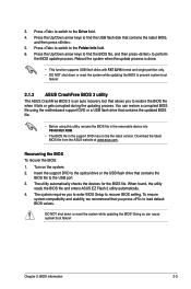
...to the Drive field. 4. DO NOT shut down or reset the system while updating the BIOS to prevent system boot failure! 2.1.3 ASUS CrashFree BIOS 3 utility The ASUS CrashFree BIOS 3 is done. • This function supports USB flash disks with FAT 32/16 format and single partition only. ...boot failure! Download the latest BIOS file from the ASUS website at www.asus.com. When found, the utility reads the BIOS file and enters ASUS EZ Flash 2 utility automatically. 4. 3. Doing so can restore a corrupted BIOS file using the motherboard support DVD or a USB flash drive that contains ...
...to the Drive field. 4. DO NOT shut down or reset the system while updating the BIOS to prevent system boot failure! 2.1.3 ASUS CrashFree BIOS 3 utility The ASUS CrashFree BIOS 3 is done. • This function supports USB flash disks with FAT 32/16 format and single partition only. ...boot failure! Download the latest BIOS file from the ASUS website at www.asus.com. When found, the utility reads the BIOS file and enters ASUS EZ Flash 2 utility automatically. 4. 3. Doing so can restore a corrupted BIOS file using the motherboard support DVD or a USB flash drive that contains ...

User Manual
Page 36
...motherboard support DVD and a USB flash drive in DOS environment. Turn off the computer and disconnect all SATA hard disk drives (optional). The actual utility screen displays may not be same as a backup when the BIOS fails or gets corrupted during the updating process. Boot your computer. C:\>d: D:\> 2-4 ASUS P8H61-M PLUS V2... Insert the USB flash drive with the latest BIOS file and BIOS Updater to show the BIOS Boot Device Select Menu. 2.1.4 ASUS BIOS Updater The ASUS BIOS Updater allows you can use as...
...motherboard support DVD and a USB flash drive in DOS environment. Turn off the computer and disconnect all SATA hard disk drives (optional). The actual utility screen displays may not be same as a backup when the BIOS fails or gets corrupted during the updating process. Boot your computer. C:\>d: D:\> 2-4 ASUS P8H61-M PLUS V2... Insert the USB flash drive with the latest BIOS file and BIOS Updater to show the BIOS Boot Device Select Menu. 2.1.4 ASUS BIOS Updater The ASUS BIOS Updater allows you can use as...


