
User Manual
Page 1
Motherboard P8H61-M LE P8H61-M LE/USB3
Motherboard P8H61-M LE P8H61-M LE/USB3

User Manual
Page 3
Contents Notices...vi Safety information vii About this guide viii P8H61-M LE Series specifications summary ix Chapter 1: Product introduction 1.1 Welcome 1-1 1.2 Package contents 1-1 1.3 Special features 1-1 1.3.1 Product highlights 1-1 1.3.2 Innovative ASUS features 1-3 1.4 Before you proceed 1-5 1.5 Motherboard overview 1-6 1.5.1 Placement direction 1-6 1.5.2 Screw holes 1-6 1.5.3 Motherboard layout 1-7 1.5.4 Layout contents 1-8 1.6 Central Processing Unit (CPU 1-9 1.6.1 Installing the CPU 1-9 1.6.2 Installing the CPU heatsink ...
Contents Notices...vi Safety information vii About this guide viii P8H61-M LE Series specifications summary ix Chapter 1: Product introduction 1.1 Welcome 1-1 1.2 Package contents 1-1 1.3 Special features 1-1 1.3.1 Product highlights 1-1 1.3.2 Innovative ASUS features 1-3 1.4 Before you proceed 1-5 1.5 Motherboard overview 1-6 1.5.1 Placement direction 1-6 1.5.2 Screw holes 1-6 1.5.3 Motherboard layout 1-7 1.5.4 Layout contents 1-8 1.6 Central Processing Unit (CPU 1-9 1.6.1 Installing the CPU 1-9 1.6.2 Installing the CPU heatsink ...
User Manual
Page 9
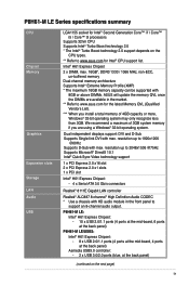
... back panel) P8H61-M LE/USB3: Intel® H61 Express Chipset: - 8 x USB 2.0/1.1 ports (4 ports at the mid-board, 4 ports at the back panel) Asmedia USB3.0 controller: - 2 x USB 3.0/2.0 ports (blue, at the back panel) (continued on the CPU types. ** Refer to www.asus.com for Intel... memory architecture Supports Intel® Extreme Memory Profile (XMP) * The maximum 16GB memory capacity can be supported with max. P8H61-M LE Series specifications summary CPU Chipset Memory Graphics Expansion slots Storage LAN Audio USB LGA1155 socket for Intel® Second Generation Core™...
... back panel) P8H61-M LE/USB3: Intel® H61 Express Chipset: - 8 x USB 2.0/1.1 ports (4 ports at the mid-board, 4 ports at the back panel) Asmedia USB3.0 controller: - 2 x USB 3.0/2.0 ports (blue, at the back panel) (continued on the CPU types. ** Refer to www.asus.com for Intel... memory architecture Supports Intel® Extreme Memory Profile (XMP) * The maximum 16GB memory capacity can be supported with max. P8H61-M LE Series specifications summary CPU Chipset Memory Graphics Expansion slots Storage LAN Audio USB LGA1155 socket for Intel® Second Generation Core™...

User Manual
Page 10
... connectors/ switches/ buttons BIOS features Accessories Support DVD Form factor ESD GPU Boost ASUS Anti-Surge Protection ASUS EPU ASUS TurboV ASUS Fan Xpert ASUS EFI BIOS ASUS AI Suite II ASUS CrashFree BIOS 3 ASUS EZ Flash 2 ASUS MyLogo 2™ 100% All High-quality Conductive Polymer Capacitors (P8H61-M LE/USB3 only) 1 x PS/2 keyboard / mouse combo port 1 x DVI-D port 1 x D-Sub port 1 x LAN...
... connectors/ switches/ buttons BIOS features Accessories Support DVD Form factor ESD GPU Boost ASUS Anti-Surge Protection ASUS EPU ASUS TurboV ASUS Fan Xpert ASUS EFI BIOS ASUS AI Suite II ASUS CrashFree BIOS 3 ASUS EZ Flash 2 ASUS MyLogo 2™ 100% All High-quality Conductive Polymer Capacitors (P8H61-M LE/USB3 only) 1 x PS/2 keyboard / mouse combo port 1 x DVI-D port 1 x D-Sub port 1 x LAN...
User Manual
Page 11
... new features and latest technologies, making it , check the items in the world. Before you for the following items. Motherboard Cables Accessories Application DVD Documentation ASUS P8H61-M LE Series motherboard 2 x Serial ATA 3.0Gb/s cables 1 x I/O shield ASUS motherboard support DVD User Manual • P8H61-M LE Series motherboards include P8H61-M LE and P8H61-M LE/USB3 two models.
... new features and latest technologies, making it , check the items in the world. Before you for the following items. Motherboard Cables Accessories Application DVD Documentation ASUS P8H61-M LE Series motherboard 2 x Serial ATA 3.0Gb/s cables 1 x I/O shield ASUS motherboard support DVD User Manual • P8H61-M LE Series motherboards include P8H61-M LE and P8H61-M LE/USB3 two models.
User Manual
Page 12
...management function to provide efficient power management for advanced operating systems. 100% All High-quality Conductive Polymer Capacitors (P8H61-M LE/USB3 only) This motherboard uses all high-quality conductive polymer capacitors for double speed and bandwidth which enhances system ... processors. PCI Express 2.0 support This motherboard supports PCI Express 2.0 devices for durability, improved lifespan, and enhanced thermal capacity. 1-2 ASUS P8H61-M LE Series It is also backward compatible with USB 2.0 components. Intel® H61 Express Chipset The Intel® H61 Express Chipset is...
...management function to provide efficient power management for advanced operating systems. 100% All High-quality Conductive Polymer Capacitors (P8H61-M LE/USB3 only) This motherboard uses all high-quality conductive polymer capacitors for double speed and bandwidth which enhances system ... processors. PCI Express 2.0 support This motherboard supports PCI Express 2.0 devices for durability, improved lifespan, and enhanced thermal capacity. 1-2 ASUS P8H61-M LE Series It is also backward compatible with USB 2.0 components. Intel® H61 Express Chipset The Intel® H61 Express Chipset is...

User Manual
Page 14
...and reboot the system, and the BIOS automatically restores the CPU parameters to open the system chassis and clear the RTC data. ASUS MyLogo2™ This feature allows you to restore a corrupted BIOS file using an OS-based utility. ErP ready The motherboard is...allows you to overclocking failure. eliminates the need to their default settings. ASUS EZ Flash 2 ASUS EZ Flash 2 is in regards to reduce carbon footprint of the product and thus mitigate environmental impacts. 1-4 ASUS P8H61-M LE Series feature automatically restores the CPU default settings when the system hangs ...
...and reboot the system, and the BIOS automatically restores the CPU parameters to open the system chassis and clear the RTC data. ASUS MyLogo2™ This feature allows you to restore a corrupted BIOS file using an OS-based utility. ErP ready The motherboard is...allows you to overclocking failure. eliminates the need to their default settings. ASUS EZ Flash 2 ASUS EZ Flash 2 is in regards to reduce carbon footprint of the product and thus mitigate environmental impacts. 1-4 ASUS P8H61-M LE Series feature automatically restores the CPU default settings when the system hangs ...
User Manual
Page 15
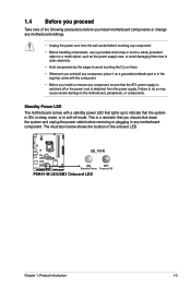
... ICs on them. • Whenever you uninstall any component, place it on a grounded antistatic pad or in any motherboard component. SB_PWR P8H61-M LE/USB3 ON OFF Standby Power Powered Off P8H61-M LE/USB3 Onboard LED Chapter 1: Product introduction 1-5 Failure to do so may cause severe damage to indicate that the system is ON, in...
... ICs on them. • Whenever you uninstall any component, place it on a grounded antistatic pad or in any motherboard component. SB_PWR P8H61-M LE/USB3 ON OFF Standby Power Powered Off P8H61-M LE/USB3 Onboard LED Chapter 1: Product introduction 1-5 Failure to do so may cause severe damage to indicate that the system is ON, in...
User Manual
Page 16
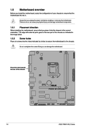
... configuration of your chassis to ensure that you place it into it. The edge with external ports goes to the rear part of the chassis P8H61-M LE/USB3 1-6 ASUS P8H61-M LE Series Doing so can cause you physical injury and damage motherboard components. 1.5.1 Placement direction When installing the motherboard, ensure that the motherboard fits into...
... configuration of your chassis to ensure that you place it into it. The edge with external ports goes to the rear part of the chassis P8H61-M LE/USB3 1-6 ASUS P8H61-M LE Series Doing so can cause you physical injury and damage motherboard components. 1.5.1 Placement direction When installing the motherboard, ensure that the motherboard fits into...
User Manual
Page 17
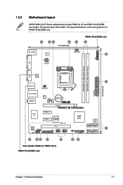
...introduction 1-7 The layout varies with models. 1.5.3 Motherboard layout ASUS P8H61-M LE Series motherboards include P8H61-M LE and P8H61-M LE/USB3 two models. The layout illustrations in this user guide are for P8H61-M LE/USB3 only. 1 23 4 1 20.3cm(8.0in) P8H61-M LE/USB3 only 5 KB_USB56 EPU CPU_FAN 6 TPM DVI ATX12V...asmedia ASM1042 2 USB3_12 CHA_FAN 24.4cm(9.6in) EATXPWR LAN1_USB12 AUDIO RTL 8111E COM1 Lithium Cell CMOS Power PCIEX16 P8H61-M LE/USB3 Super I/O PCIEX1_1 Intel® PCIEX1_2 asmedia ASM1083 H61 32Mb BIOS SB_PWR ALC 887 SPDIF_OUT AAFP PCI1 LPT...
...introduction 1-7 The layout varies with models. 1.5.3 Motherboard layout ASUS P8H61-M LE Series motherboards include P8H61-M LE and P8H61-M LE/USB3 two models. The layout illustrations in this user guide are for P8H61-M LE/USB3 only. 1 23 4 1 20.3cm(8.0in) P8H61-M LE/USB3 only 5 KB_USB56 EPU CPU_FAN 6 TPM DVI ATX12V...asmedia ASM1042 2 USB3_12 CHA_FAN 24.4cm(9.6in) EATXPWR LAN1_USB12 AUDIO RTL 8111E COM1 Lithium Cell CMOS Power PCIEX16 P8H61-M LE/USB3 Super I/O PCIEX1_1 Intel® PCIEX1_2 asmedia ASM1083 H61 32Mb BIOS SB_PWR ALC 887 SPDIF_OUT AAFP PCI1 LPT...
User Manual
Page 19
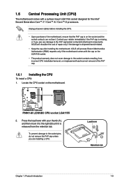
...P8H61-M LE/USB3 P8H61-M LE/USB3 CPU socket LGA1155 2. To prevent damage to the socket pins, do not remove the PnP cap unless you see any damage to the PnP cap/socket contacts/motherboard components. 1.6 Central Processing Unit (CPU) The motherboard comes with the cap on the motherboard. ASUS...all power cables before installing the CPU. • Upon purchase of the PnP cap. 1.6.1 Installing the CPU To install a CPU: 1. ASUS will process Return Merchandise Authorization (RMA) requests only if the motherboard comes with a surface mount LGA1155 socket designed for the Intel® Second ...
...P8H61-M LE/USB3 P8H61-M LE/USB3 CPU socket LGA1155 2. To prevent damage to the socket pins, do not remove the PnP cap unless you see any damage to the PnP cap/socket contacts/motherboard components. 1.6 Central Processing Unit (CPU) The motherboard comes with the cap on the motherboard. ASUS...all power cables before installing the CPU. • Upon purchase of the PnP cap. 1.6.1 Installing the CPU To install a CPU: 1. ASUS will process Return Merchandise Authorization (RMA) requests only if the motherboard comes with a surface mount LGA1155 socket designed for the Intel® Second ...
User Manual
Page 20
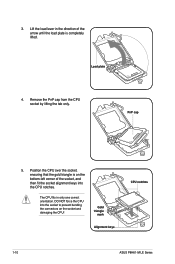
... connectors on the bottom‑left corner of the arrow until the load plate is completely lifted. Gold triangle mark Alignment keys CPU notches 1-10 ASUS P8H61-M LE Series Load plate 4. Remove the PnP cap from the CPU socket by lifting the tab only. Position the CPU over the socket, ensuring that the...
... connectors on the bottom‑left corner of the arrow until the load plate is completely lifted. Gold triangle mark Alignment keys CPU notches 1-10 ASUS P8H61-M LE Series Load plate 4. Remove the PnP cap from the CPU socket by lifting the tab only. Position the CPU over the socket, ensuring that the...
User Manual
Page 22
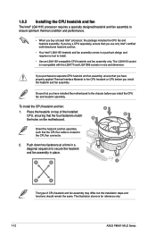
B B Orient the heatsink and fan assembly A such that the CPU fan cable is for reference only. 1-12 ASUS P8H61-M LE Series Place the heatsink on the motherboard. The illustration above is closest to the CPU fan connector. 2. The LGA1155 socket is incompatible with the LGA775 ...
B B Orient the heatsink and fan assembly A such that the CPU fan cable is for reference only. 1-12 ASUS P8H61-M LE Series Place the heatsink on the motherboard. The illustration above is closest to the CPU fan connector. 2. The LGA1155 socket is incompatible with the LGA775 ...
User Manual
Page 23
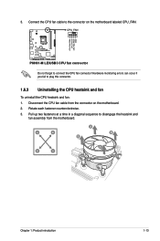
Disconnect the CPU fan cable from the motherboard. CPU_FAN CPU FAN PWM CPU FAN IN CPU FAN PWR GND P8H61-M LE/USB3 P8H61-M LE/USB3 CPU fan connector Do not forget to plug this connector. 1.6.3 Uninstalling the CPU heatsink and fan To uninstall the CPU heatsink and fan: 1. Hardware ...
Disconnect the CPU fan cable from the motherboard. CPU_FAN CPU FAN PWM CPU FAN IN CPU FAN PWR GND P8H61-M LE/USB3 P8H61-M LE/USB3 CPU fan connector Do not forget to plug this connector. 1.6.3 Uninstalling the CPU heatsink and fan To uninstall the CPU heatsink and fan: 1. Hardware ...
User Manual
Page 24
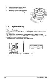
The figure illustrates the location of the DDR3 DIMM sockets: DIMM_A1 DIMM_B1 P8H61-M LE/USB3 Channel Channel A Channel B Sockets DIMM_A1 DIMM_B1 P8H61-M LE/USB3 240-pin DDR3 DIMM sockets 1-14 ASUS P8H61-M LE Series A DDR3 module has the same physical dimensions as a DDR2 DIMM but is notched differently to ensure correct orientation when reinstalling. 1.7 System memory 1.7.1 Overview The...
The figure illustrates the location of the DDR3 DIMM sockets: DIMM_A1 DIMM_B1 P8H61-M LE/USB3 Channel Channel A Channel B Sockets DIMM_A1 DIMM_B1 P8H61-M LE/USB3 240-pin DDR3 DIMM sockets 1-14 ASUS P8H61-M LE Series A DDR3 module has the same physical dimensions as a DDR2 DIMM but is notched differently to ensure correct orientation when reinstalling. 1.7 System memory 1.7.1 Overview The...
User Manual
Page 25
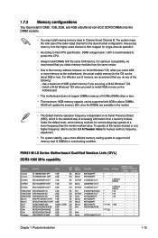
... the market. • The default memory operation frequency is recommended to protect the CPU. • Always install DIMMs with 8GB or above DIMMs. ASUS will update the memory QVL once the DIMMs are using a 32-bit Windows® OS. - Under the default state, some memory modules for...into the DIMM sockets. • You may operate at a higher frequency, refer to section 2.4 Ai Tweaker menu for the dual-channel configuration. P8H61-M LE Series Motherboard Qualified Vendors Lists (QVL) DDR3-1066 MHz capability Vendors Part No. The system maps the total size of the lower-sized channel ...
... the market. • The default memory operation frequency is recommended to protect the CPU. • Always install DIMMs with 8GB or above DIMMs. ASUS will update the memory QVL once the DIMMs are using a 32-bit Windows® OS. - Under the default state, some memory modules for...into the DIMM sockets. • You may operate at a higher frequency, refer to section 2.4 Ai Tweaker menu for the dual-channel configuration. P8H61-M LE Series Motherboard Qualified Vendors Lists (QVL) DDR3-1066 MHz capability Vendors Part No. The system maps the total size of the lower-sized channel ...
User Manual
Page 26
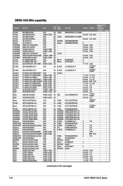
... • • OCZ3P1333LV4GK 4GB(2 x 2GB) DS - - 7-7-7-20 1.65V • • OCZ3X13334GK(XMP) 4GB(2 x 2GB) DS - - 7-7-7-20 1.75V • • (continued on the next page) 1-16 ASUS P8H61-M LE Series DDR3-1333 MHz capability Vendors A-Data A-Data A-Data A-Data Apacer Apacer CORSAIR CORSAIR CORSAIR CORSAIR CORSAIR CORSAIR CORSAIR Crucial Crucial Crucial ELPIDA ELPIDA G.SKILL...
... • • OCZ3P1333LV4GK 4GB(2 x 2GB) DS - - 7-7-7-20 1.65V • • OCZ3X13334GK(XMP) 4GB(2 x 2GB) DS - - 7-7-7-20 1.75V • • (continued on the next page) 1-16 ASUS P8H61-M LE Series DDR3-1333 MHz capability Vendors A-Data A-Data A-Data A-Data Apacer Apacer CORSAIR CORSAIR CORSAIR CORSAIR CORSAIR CORSAIR CORSAIR Crucial Crucial Crucial ELPIDA ELPIDA G.SKILL...
User Manual
Page 28
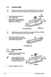
... DIMM might get damaged when it fits in the wrong direction to unlock the DIMM. 2 Support the DIMM lightly with extra force. 1 2. DIMM notch 1-18 ASUS P8H61-M LE Series DO NOT force a DIMM into the socket until the retaining clips snap back in place 3 and the DIMM is keyed with a notch so that...
... DIMM might get damaged when it fits in the wrong direction to unlock the DIMM. 2 Support the DIMM lightly with extra force. 1 2. DIMM notch 1-18 ASUS P8H61-M LE Series DO NOT force a DIMM into the socket until the retaining clips snap back in place 3 and the DIMM is keyed with a notch so that...
User Manual
Page 30
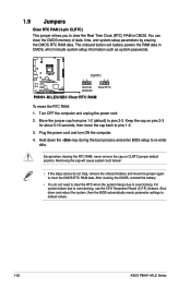
...and move the cap back to pins 1-2. 3. Hold down and reboot the system, then the BIOS automatically resets parameter settings to default values. 1-20 ASUS P8H61-M LE Series 1.9 Jumpers Clear RTC RAM (3-pin CLRTC) This jumper allows you to clear the Real Time Clock (RTC) RAM in CMOS, which include ... for about 5-10 seconds, then move the jumper again to re-enter data. For system failure due to pins 2-3. P8H61-M LE/USB3 CLRTC 12 23 Normal (Default) Clear RTC P8H61-M LE/USB3 Clear RTC RAM To erase the RTC RAM: 1. Shut down the key during the boot process and enter BIOS ...
...and move the cap back to pins 1-2. 3. Hold down and reboot the system, then the BIOS automatically resets parameter settings to default values. 1-20 ASUS P8H61-M LE Series 1.9 Jumpers Clear RTC RAM (3-pin CLRTC) This jumper allows you to clear the Real Time Clock (RTC) RAM in CMOS, which include ... for about 5-10 seconds, then move the jumper again to re-enter data. For system failure due to pins 2-3. P8H61-M LE/USB3 CLRTC 12 23 Normal (Default) Clear RTC P8H61-M LE/USB3 Clear RTC RAM To erase the RTC RAM: 1. Shut down the key during the boot process and enter BIOS ...
User Manual
Page 32
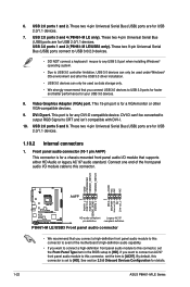
... default, this connector is for USB 2.0/1.1 devices. 7. These two 4-pin Universal Serial Bus (USB) ports are for details. 1-22 ASUS P8H61-M LE Series See section 2.5.6 Onboard Devices Configuration for USB 2.0/1.1 devices. USB 3.0 ports 1 and 2 (P8H61-M LE/USB3 only). DVI-D can't be used under Windows® OS environment and after the USB 3.0 driver installation. • USB...
... default, this connector is for USB 2.0/1.1 devices. 7. These two 4-pin Universal Serial Bus (USB) ports are for details. 1-22 ASUS P8H61-M LE Series See section 2.5.6 Onboard Devices Configuration for USB 2.0/1.1 devices. USB 3.0 ports 1 and 2 (P8H61-M LE/USB3 only). DVI-D can't be used under Windows® OS environment and after the USB 3.0 driver installation. • USB...


