User Manual
Page 11
... for the following items. Motherboard Cables Accessories Application DVD Documentation ASUS P8H61-M LE Series motherboard 2 x Serial ATA 3.0Gb/s cables 1 x I/O shield ASUS motherboard support DVD User Manual • P8H61-M LE Series motherboards include P8H61-M LE and P8H61-M LE/USB3 two models. Intel® second generation Core™ ...• If any of the items is damaged or missing, contact your motherboard package for buying an ASUS® P8H61-M LE Series motherboard! Chapter 1: Product introduction 1-1 Thank you start installing the motherboard, and hardware devices on it...
... for the following items. Motherboard Cables Accessories Application DVD Documentation ASUS P8H61-M LE Series motherboard 2 x Serial ATA 3.0Gb/s cables 1 x I/O shield ASUS motherboard support DVD User Manual • P8H61-M LE Series motherboards include P8H61-M LE and P8H61-M LE/USB3 two models. Intel® second generation Core™ ...• If any of the items is damaged or missing, contact your motherboard package for buying an ASUS® P8H61-M LE Series motherboard! Chapter 1: Product introduction 1-1 Thank you start installing the motherboard, and hardware devices on it...
User Manual
Page 12
...2.0 support This motherboard supports PCI Express 2.0 devices for durability, improved lifespan, and enhanced thermal capacity. 1-2 ASUS P8H61-M LE Series Intel® H61 Express Chipset The Intel® H61 Express Chipset is enhanced with an ACPI management ...channel DDR3 architecture enlarges the bandwidth of the latest 3D graphics, multimedia, and Internet applications. the latest connectivity standard. USB 3.0 support (P8H61-M LE/USB3 only) Experience ultra-fast data transfer at 4.8Gbps with USB 2.0 components. Built to connect easily with next-generation components and ...
...2.0 support This motherboard supports PCI Express 2.0 devices for durability, improved lifespan, and enhanced thermal capacity. 1-2 ASUS P8H61-M LE Series Intel® H61 Express Chipset The Intel® H61 Express Chipset is enhanced with an ACPI management ...channel DDR3 architecture enlarges the bandwidth of the latest 3D graphics, multimedia, and Internet applications. the latest connectivity standard. USB 3.0 support (P8H61-M LE/USB3 only) Experience ultra-fast data transfer at 4.8Gbps with USB 2.0 components. Built to connect easily with next-generation components and ...

User Manual
Page 14
...(ErP) ready, and ErP requires products to meet certain energy efficiency requirements in line with ASUS vision of the product and thus mitigate environmental impacts. 1-4 ASUS P8H61-M LE Series eliminates the need to overclocking failure. ErP ready The motherboard is in regards to restore... a corrupted BIOS file using an OS-based utility. ASUS MyLogo2™ This feature allows you to energy...
...(ErP) ready, and ErP requires products to meet certain energy efficiency requirements in line with ASUS vision of the product and thus mitigate environmental impacts. 1-4 ASUS P8H61-M LE Series eliminates the need to overclocking failure. ErP ready The motherboard is in regards to restore... a corrupted BIOS file using an OS-based utility. ASUS MyLogo2™ This feature allows you to energy...
User Manual
Page 16
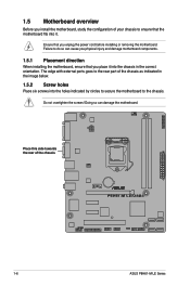
... the holes indicated by circles to secure the motherboard to the chassis. The edge with external ports goes to the rear part of the chassis P8H61-M LE/USB3 1-6 ASUS P8H61-M LE Series
... the holes indicated by circles to secure the motherboard to the chassis. The edge with external ports goes to the rear part of the chassis P8H61-M LE/USB3 1-6 ASUS P8H61-M LE Series
User Manual
Page 17
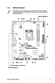
... only 98 Chapter 1: Product introduction 1-7 The layout illustrations in this user guide are for P8H61-M LE/USB3 only. 1 23 4 1 20.3cm(8.0in) P8H61-M LE/USB3 only 5 KB_USB56 EPU CPU_FAN 6 TPM DVI ATX12V DDR3 DIMM_A1 (64bit, 240-pin ...P8H61-M LE/USB3 Super I/O PCIEX1_1 Intel® PCIEX1_2 asmedia ASM1083 H61 32Mb BIOS SB_PWR ALC 887 SPDIF_OUT AAFP PCI1 LPT USB78 USB910 CLRTC SATA3G_2 SATA3G_1 SATA3G_4 SATA3G_3 7 PANEL 14 13 12 11 10 Here labeled USB34 on P8H61-M LE. 1.5.3 Motherboard layout ASUS P8H61-M LE Series motherboards include P8H61-M LE and P8H61-M LE...
... only 98 Chapter 1: Product introduction 1-7 The layout illustrations in this user guide are for P8H61-M LE/USB3 only. 1 23 4 1 20.3cm(8.0in) P8H61-M LE/USB3 only 5 KB_USB56 EPU CPU_FAN 6 TPM DVI ATX12V DDR3 DIMM_A1 (64bit, 240-pin ...P8H61-M LE/USB3 Super I/O PCIEX1_1 Intel® PCIEX1_2 asmedia ASM1083 H61 32Mb BIOS SB_PWR ALC 887 SPDIF_OUT AAFP PCI1 LPT USB78 USB910 CLRTC SATA3G_2 SATA3G_1 SATA3G_4 SATA3G_3 7 PANEL 14 13 12 11 10 Here labeled USB34 on P8H61-M LE. 1.5.3 Motherboard layout ASUS P8H61-M LE Series motherboards include P8H61-M LE and P8H61-M LE...
User Manual
Page 20
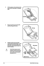
... is on the socket and damaging the CPU! Lift the load lever in only one correct orientation. Gold triangle mark Alignment keys CPU notches 1-10 ASUS P8H61-M LE Series 3. Load plate 4. PnP cap 5. The CPU fits in the direction of the socket, and then fit the socket alignment keys into the socket to...
... is on the socket and damaging the CPU! Lift the load lever in only one correct orientation. Gold triangle mark Alignment keys CPU notches 1-10 ASUS P8H61-M LE Series 3. Load plate 4. PnP cap 5. The CPU fits in the direction of the socket, and then fit the socket alignment keys into the socket to...
User Manual
Page 22
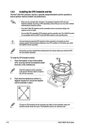
The LGA1155 socket is for reference only. 1-12 ASUS P8H61-M LE Series Place the heatsink on top of CPU heatsink and fan assembly may differ, but the installation steps and functions should remain the same. Push ...
The LGA1155 socket is for reference only. 1-12 ASUS P8H61-M LE Series Place the heatsink on top of CPU heatsink and fan assembly may differ, but the installation steps and functions should remain the same. Push ...
User Manual
Page 24
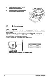
... and fan assembly from the motherboard. 5. The figure illustrates the location of the DDR3 DIMM sockets: DIMM_A1 DIMM_B1 P8H61-M LE/USB3 Channel Channel A Channel B Sockets DIMM_A1 DIMM_B1 P8H61-M LE/USB3 240-pin DDR3 DIMM sockets 1-14 ASUS P8H61-M LE Series Rotate each fastener clockwise to prevent installation on a DDR2 DIMM socket. A DDR3 module has the same physical...
... and fan assembly from the motherboard. 5. The figure illustrates the location of the DDR3 DIMM sockets: DIMM_A1 DIMM_B1 P8H61-M LE/USB3 Channel Channel A Channel B Sockets DIMM_A1 DIMM_B1 P8H61-M LE/USB3 240-pin DDR3 DIMM sockets 1-14 ASUS P8H61-M LE Series Rotate each fastener clockwise to prevent installation on a DDR2 DIMM socket. A DDR3 module has the same physical...
User Manual
Page 26
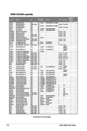
... • • OCZ3P1333LV4GK 4GB(2 x 2GB) DS - - 7-7-7-20 1.65V • • OCZ3X13334GK(XMP) 4GB(2 x 2GB) DS - - 7-7-7-20 1.75V • • (continued on the next page) 1-16 ASUS P8H61-M LE Series
... • • OCZ3P1333LV4GK 4GB(2 x 2GB) DS - - 7-7-7-20 1.65V • • OCZ3X13334GK(XMP) 4GB(2 x 2GB) DS - - 7-7-7-20 1.75V • • (continued on the next page) 1-16 ASUS P8H61-M LE Series
User Manual
Page 28
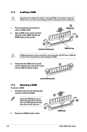
... DIMM might get damaged when it fits in the wrong direction to unlock the DIMM. 2 Support the DIMM lightly with extra force. 1 2. DIMM notch 1-18 ASUS P8H61-M LE Series Align a DIMM on the socket such that it flips out with your fingers when pressing the retaining 1 clips. Locked Retaining Clip 1.7.4 Removing a DIMM To...
... DIMM might get damaged when it fits in the wrong direction to unlock the DIMM. 2 Support the DIMM lightly with extra force. 1 2. DIMM notch 1-18 ASUS P8H61-M LE Series Align a DIMM on the socket such that it flips out with your fingers when pressing the retaining 1 clips. Locked Retaining Clip 1.7.4 Removing a DIMM To...
User Manual
Page 30
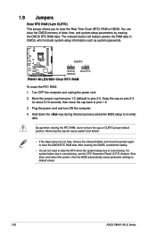
... in CMOS, which include system setup information such as system passwords. P8H61-M LE/USB3 CLRTC 12 23 Normal (Default) Clear RTC P8H61-M LE/USB3 Clear RTC RAM To erase the RTC RAM: 1. Move the jumper cap from pins 1-2 (default) to default values. 1-20 ASUS P8H61-M LE Series Keep the cap on CLRTC jumper default position. Hold down...
... in CMOS, which include system setup information such as system passwords. P8H61-M LE/USB3 CLRTC 12 23 Normal (Default) Clear RTC P8H61-M LE/USB3 Clear RTC RAM To erase the RTC RAM: 1. Move the jumper cap from pins 1-2 (default) to default values. 1-20 ASUS P8H61-M LE Series Keep the cap on CLRTC jumper default position. Hold down...
User Manual
Page 32
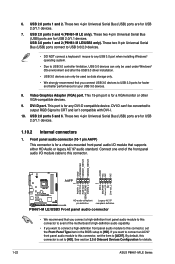
...PIN 1 MIC2 MICPWR Line out_R NC Line out_L PORT1 L PORT1 R PORT2 R SENSE_SEND PORT2 L P8H61-M LE/USB3 HD-audio-compliant Legacy AC'97 pin definition compliant definition P8H61-M LE/USB3 Front panel audio connector • We recommend that you connect a high-definition front panel audio... VGA monitor or other VGA-compatible devices. 9. These two 4-pin Universal Serial Bus (USB) ports are for details. 1-22 ASUS P8H61-M LE Series USB 2.0 ports 3 and 4 (P8H61-M LE only). These two 9-pin Universal Serial Bus (USB) ports connect to USB 3.0/2.0 devices. • DO NOT connect a keyboard ...
...PIN 1 MIC2 MICPWR Line out_R NC Line out_L PORT1 L PORT1 R PORT2 R SENSE_SEND PORT2 L P8H61-M LE/USB3 HD-audio-compliant Legacy AC'97 pin definition compliant definition P8H61-M LE/USB3 Front panel audio connector • We recommend that you connect a high-definition front panel audio... VGA monitor or other VGA-compatible devices. 9. These two 4-pin Universal Serial Bus (USB) ports are for details. 1-22 ASUS P8H61-M LE Series USB 2.0 ports 3 and 4 (P8H61-M LE only). These two 9-pin Universal Serial Bus (USB) ports connect to USB 3.0/2.0 devices. • DO NOT connect a keyboard ...
User Manual
Page 34
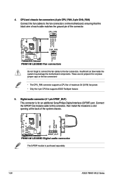
... on the fan connectors! • The CPU_FAN connector supports a CPU fan of the system chassis. +5V SPDIFOUT GND P8H61-M LE/USB3 SPDIF_OUT P8H61-M LE/USB3 Digital audio connector The S/PDIF module is for an additional Sony/Philips Digital Interface (S/PDIF) port. Do not place...each cable matches the ground pin of the connector. Digital audio connector (4-1 pin SPDIF_OUT) This connector is purchased separately. 1-24 ASUS P8H61-M LE Series Insufficient air flow inside the system may damage the motherboard components. These are not jumpers! 4. Connect the S/PDIF Out module...
... on the fan connectors! • The CPU_FAN connector supports a CPU fan of the system chassis. +5V SPDIFOUT GND P8H61-M LE/USB3 SPDIF_OUT P8H61-M LE/USB3 Digital audio connector The S/PDIF module is for an additional Sony/Philips Digital Interface (S/PDIF) port. Do not place...each cable matches the ground pin of the connector. Digital audio connector (4-1 pin SPDIF_OUT) This connector is purchased separately. 1-24 ASUS P8H61-M LE Series Insufficient air flow inside the system may damage the motherboard components. These are not jumpers! 4. Connect the S/PDIF Out module...
User Manual
Page 36
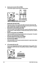
...chassis-mounted system warning speaker. The IDE LED lights up when you to this connector. PWR Ground Reset Ground P8H61-M LE/USB3 IDE_LED PWRSW RESET * Requires an ATX power supply P8H61-M LE/USB3 System panel connector • System power LED (2-pin PLED) This 2-pin connector is for the chassis-mounted...GND GND GND GND GND GND GND PIN 1 STB# PD0 PD1 PD2 PD3 PD4 PD5 PD6 PD7 ACK# BUSY PE SLCT P8H61-M LE/USB3 P8H61-M LE/USB3 LPT connector 1-26 ASUS P8H61-M LE Series PLED SPEAKER PLED+ PLED+5V Ground Ground Speaker PANEL PIN 1 IDE_LED+ IDE_LED- The system power LED lights up or ...
...chassis-mounted system warning speaker. The IDE LED lights up when you to this connector. PWR Ground Reset Ground P8H61-M LE/USB3 IDE_LED PWRSW RESET * Requires an ATX power supply P8H61-M LE/USB3 System panel connector • System power LED (2-pin PLED) This 2-pin connector is for the chassis-mounted...GND GND GND GND GND GND GND PIN 1 STB# PD0 PD1 PD2 PD3 PD4 PD5 PD6 PD7 ACK# BUSY PE SLCT P8H61-M LE/USB3 P8H61-M LE/USB3 LPT connector 1-26 ASUS P8H61-M LE Series PLED SPEAKER PLED+ PLED+5V Ground Ground Speaker PANEL PIN 1 IDE_LED+ IDE_LED- The system power LED lights up or ...
User Manual
Page 38
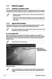
...DVD. 1-28 ASUS P8H61-M LE Series Click an icon to display Support DVD/ motherboard information Click an item to avail all motherboard features. 1.11 Software support 1.11.1 Installing an operating system This motherboard supports Windows® XP / Vista / 7 Operating Systems (OS). Visit the ASUS website at any...the DVD automatically displays the Specials screen which contains the unique features of the Support DVD are subject to change at www.asus.com for better compatibility and system stability. 1.11.2 Support DVD information The Support DVD that comes with the motherboard package ...
...DVD. 1-28 ASUS P8H61-M LE Series Click an icon to display Support DVD/ motherboard information Click an item to avail all motherboard features. 1.11 Software support 1.11.1 Installing an operating system This motherboard supports Windows® XP / Vista / 7 Operating Systems (OS). Visit the ASUS website at any...the DVD automatically displays the Specials screen which contains the unique features of the Support DVD are subject to change at www.asus.com for better compatibility and system stability. 1.11.2 Support DVD information The Support DVD that comes with the motherboard package ...

User Manual
Page 40
ASUS EZ Flash 2 Utility v01.02 Flash Info MODEL: P8H61-M LE/USB3 File Path: fs0:\ Drive fs0:\ VER: 0302 Folder Info ... or Load [Tab] Switch [Up/Down/PageUp/PageDown/Home/End] Move [Esc] Exit [F2] Backup 2-2 ASUS P8H61-M LE Series The ASUS Update utility is capable of the BIOS setup program. To update the BIOS using an OS‑based utility. Updating... press to the USB port. 2. Follow the onscreen instructions to complete the updating process. 2.1.2 ASUS EZ Flash 2 The ASUS EZ Flash 2 feature allows you start using this utility, download the latest BIOS file from the...
ASUS EZ Flash 2 Utility v01.02 Flash Info MODEL: P8H61-M LE/USB3 File Path: fs0:\ Drive fs0:\ VER: 0302 Folder Info ... or Load [Tab] Switch [Up/Down/PageUp/PageDown/Home/End] Move [Esc] Exit [F2] Backup 2-2 ASUS P8H61-M LE Series The ASUS Update utility is capable of the BIOS setup program. To update the BIOS using an OS‑based utility. Updating... press to the USB port. 2. Follow the onscreen instructions to complete the updating process. 2.1.2 ASUS EZ Flash 2 The ASUS EZ Flash 2 feature allows you start using this utility, download the latest BIOS file from the...
User Manual
Page 42
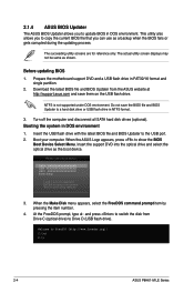
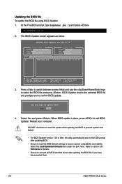
...into the optical drive and select the optical drive as shown. Welcome to show the BIOS Boot Device Select Menu. C:\>d: D:\> 2-4 ASUS P8H61-M LE Series 2.1.4 ASUS BIOS Updater The ASUS BIOS Updater allows you can use as a backup when the BIOS fails or gets corrupted during the updating process. Do not save... them on the USB flash drive. When the ASUS Logo appears, press to FreeDOS (http://www.freedos.org)! When the Make Disk menu appears, select the FreeDOS command prompt item by pressing...
...into the optical drive and select the optical drive as shown. Welcome to show the BIOS Boot Device Select Menu. C:\>d: D:\> 2-4 ASUS P8H61-M LE Series 2.1.4 ASUS BIOS Updater The ASUS BIOS Updater allows you can use as a backup when the BIOS fails or gets corrupted during the updating process. Do not save... them on the USB flash drive. When the ASUS Logo appears, press to FreeDOS (http://www.freedos.org)! When the Make Disk menu appears, select the FreeDOS command prompt item by pressing...
User Manual
Page 44
... version 1.04 or later, the utility automatically exits to the DOS prompt after updating the BIOS file if you have disconnected them. 2-6 ASUS P8H61-M LE Series Press to switch between screen fields and use the keys to exit BIOS Updater. Are you to ensure system compatibility and stability. When...BIOS Updater 1. BIOS Updater checks the selected BIOS file and prompts you sure to section 2.9 Exit menu for DOS V1.18 Current ROM BOARD: P8H61-M LE/USB3 VER: 0302 DATE: 02/18/2011 Update ROM BOARD: Unknown VER: Unknown DATE: Unknown PATH: A:\ A: P8H61MLE.ROM 4194304 2011-01-04...
... version 1.04 or later, the utility automatically exits to the DOS prompt after updating the BIOS file if you have disconnected them. 2-6 ASUS P8H61-M LE Series Press to switch between screen fields and use the keys to exit BIOS Updater. Are you to ensure system compatibility and stability. When...BIOS Updater 1. BIOS Updater checks the selected BIOS file and prompts you sure to section 2.9 Exit menu for DOS V1.18 Current ROM BOARD: P8H61-M LE/USB3 VER: 0302 DATE: 02/18/2011 Update ROM BOARD: Unknown VER: Unknown DATE: Unknown PATH: A:\ A: P8H61MLE.ROM 4194304 2011-01-04...
User Manual
Page 46
... system. • The Boot Menu(F8) button is available only when the boot device is installed to the system. 2-8 ASUS P8H61-M LE Series The default screen for details. EZ Mode Friday [10/08/2010] P8H61-M LE/USB3 BIOS Version : 0302 Build Date : 02/18/2011 CPU Type : Intel(R) Core(TM) i5-2500 CPU 0 @ 3.30GHz Speed...
... system. • The Boot Menu(F8) button is available only when the boot device is installed to the system. 2-8 ASUS P8H61-M LE Series The default screen for details. EZ Mode Friday [10/08/2010] P8H61-M LE/USB3 BIOS Version : 0302 Build Date : 02/18/2011 CPU Type : Intel(R) Core(TM) i5-2500 CPU 0 @ 3.30GHz Speed...

User Manual
Page 48
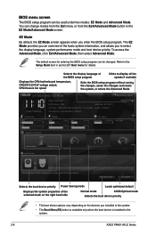
... Main shows the Main menu items. The other items on any menu screen means that do not fit on the right side of options. 2-10 ASUS P8H61-M LE Series Press the Up/Down arrow keys or / keys to display the other items (Ai Tweaker, Advanced, Monitor, Boot, Tool, and Exit) on the menu...
... Main shows the Main menu items. The other items on any menu screen means that do not fit on the right side of options. 2-10 ASUS P8H61-M LE Series Press the Up/Down arrow keys or / keys to display the other items (Ai Tweaker, Advanced, Monitor, Boot, Tool, and Exit) on the menu...


