
User Manual
Page 1
Motherboard P8H61-M LE P8H61-M LE/USB3
Motherboard P8H61-M LE P8H61-M LE/USB3
User Manual
Page 9
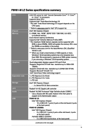
... at the back panel) P8H61-M LE/USB3: Intel® H61 Express Chipset: - 8 x USB 2.0/1.1 ports (4 ports at the mid-board, 4 ports at the back panel) Asmedia USB3.0 controller: - 2 x USB 3.0/2.0 ports (blue, at the back panel) (continued on the CPU types. ** Refer to www.asus.com for the latest Memory...resolution up to 1920x1200 @60Hz Supports D-Sub with 8GB or above DIMMs. ASUS will update the memory QVL once the DIMMs are using a Windows® 32-bit operating system. P8H61-M LE Series specifications summary CPU Chipset Memory Graphics Expansion slots Storage LAN Audio USB ...
... at the back panel) P8H61-M LE/USB3: Intel® H61 Express Chipset: - 8 x USB 2.0/1.1 ports (4 ports at the mid-board, 4 ports at the back panel) Asmedia USB3.0 controller: - 2 x USB 3.0/2.0 ports (blue, at the back panel) (continued on the CPU types. ** Refer to www.asus.com for the latest Memory...resolution up to 1920x1200 @60Hz Supports D-Sub with 8GB or above DIMMs. ASUS will update the memory QVL once the DIMMs are using a Windows® 32-bit operating system. P8H61-M LE Series specifications summary CPU Chipset Memory Graphics Expansion slots Storage LAN Audio USB ...

User Manual
Page 10
...ASUS Anti-Surge Protection ASUS EPU ASUS TurboV ASUS Fan Xpert ASUS EFI BIOS ASUS AI Suite II ASUS CrashFree BIOS 3 ASUS EZ Flash 2 ASUS MyLogo 2™ 100% All High-quality Conductive Polymer Capacitors (P8H61-M LE/USB3 only) 1 x PS/2 keyboard / mouse combo port 1 x DVI-D port 1 x D-Sub port 1 x LAN (RJ-45) port 3 x Audio jacks P8H61-M LE: 6 x USB 2.0/1.1 ports P8H61-M LE/USB3... panel audio connector 1 x S/PDIF Out connector 1 x COM connector 1 x LPT connector 1 x TPM connector (P8H61-M LE/USB3 only) 1 x System panel connector 1 x 24-pin EATX power connector 1 x 4-pin ATX 12V power connector ...
...ASUS Anti-Surge Protection ASUS EPU ASUS TurboV ASUS Fan Xpert ASUS EFI BIOS ASUS AI Suite II ASUS CrashFree BIOS 3 ASUS EZ Flash 2 ASUS MyLogo 2™ 100% All High-quality Conductive Polymer Capacitors (P8H61-M LE/USB3 only) 1 x PS/2 keyboard / mouse combo port 1 x DVI-D port 1 x D-Sub port 1 x LAN (RJ-45) port 3 x Audio jacks P8H61-M LE: 6 x USB 2.0/1.1 ports P8H61-M LE/USB3... panel audio connector 1 x S/PDIF Out connector 1 x COM connector 1 x LPT connector 1 x TPM connector (P8H61-M LE/USB3 only) 1 x System panel connector 1 x 24-pin EATX power connector 1 x 4-pin ATX 12V power connector ...
User Manual
Page 11
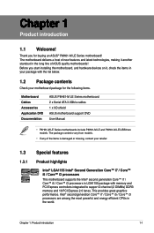
...introduction 1-1 Before you for the following items. Motherboard Cables Accessories Application DVD Documentation ASUS P8H61-M LE Series motherboard 2 x Serial ATA 3.0Gb/s cables 1 x I/O shield ASUS motherboard support DVD User Manual • P8H61-M LE Series motherboards include P8H61-M LE and P8H61-M LE/USB3 two models. This provides great graphics performance. Intel® second generation Core™... 2-channel (2 DIMMs) DDR3 memory and 16 PCI Express 2.0 lanes. The motherboard delivers a host of ASUS quality motherboards! Chapter 1 Product introduction 1.1 Welcome!
...introduction 1-1 Before you for the following items. Motherboard Cables Accessories Application DVD Documentation ASUS P8H61-M LE Series motherboard 2 x Serial ATA 3.0Gb/s cables 1 x I/O shield ASUS motherboard support DVD User Manual • P8H61-M LE Series motherboards include P8H61-M LE and P8H61-M LE/USB3 two models. This provides great graphics performance. Intel® second generation Core™... 2-channel (2 DIMMs) DDR3 memory and 16 PCI Express 2.0 lanes. The motherboard delivers a host of ASUS quality motherboards! Chapter 1 Product introduction 1.1 Welcome!
User Manual
Page 12
.... PCI Express 2.0 support This motherboard supports PCI Express 2.0 devices for durability, improved lifespan, and enhanced thermal capacity. 1-2 ASUS P8H61-M LE Series Intel® H61 Express Chipset The Intel® H61 Express Chipset is the latest single-chipset design to boost system ...ACPI management function to provide efficient power management for advanced operating systems. 100% All High-quality Conductive Polymer Capacitors (P8H61-M LE/USB3 only) This motherboard uses all high-quality conductive polymer capacitors for double speed and bandwidth which enhances system performance....
.... PCI Express 2.0 support This motherboard supports PCI Express 2.0 devices for durability, improved lifespan, and enhanced thermal capacity. 1-2 ASUS P8H61-M LE Series Intel® H61 Express Chipset The Intel® H61 Express Chipset is the latest single-chipset design to boost system ...ACPI management function to provide efficient power management for advanced operating systems. 100% All High-quality Conductive Polymer Capacitors (P8H61-M LE/USB3 only) This motherboard uses all high-quality conductive polymer capacitors for double speed and bandwidth which enhances system performance....
User Manual
Page 15
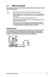
... shut down the system and unplug the power cable before removing or plugging in soft-off or the power cord is switched off mode. SB_PWR P8H61-M LE/USB3 ON OFF Standby Power Powered Off P8H61-M LE/USB3 Onboard LED Chapter 1: Product introduction 1-5
... shut down the system and unplug the power cable before removing or plugging in soft-off or the power cord is switched off mode. SB_PWR P8H61-M LE/USB3 ON OFF Standby Power Powered Off P8H61-M LE/USB3 Onboard LED Chapter 1: Product introduction 1-5
User Manual
Page 16
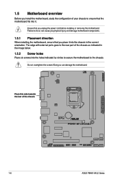
... injury and damage motherboard components. 1.5.1 Placement direction When installing the motherboard, ensure that you place it . Place this side towards the rear of the chassis P8H61-M LE/USB3 1-6 ASUS P8H61-M LE Series Do not overtighten the screws! Ensure that you unplug the power cord before installing or removing the motherboard. The edge with external ports goes...
... injury and damage motherboard components. 1.5.1 Placement direction When installing the motherboard, ensure that you place it . Place this side towards the rear of the chassis P8H61-M LE/USB3 1-6 ASUS P8H61-M LE Series Do not overtighten the screws! Ensure that you unplug the power cord before installing or removing the motherboard. The edge with external ports goes...
User Manual
Page 17
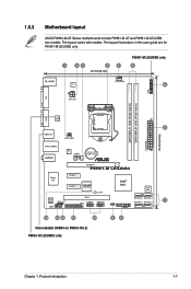
...layout varies with models. P8H61-M LE/USB3 only 98 Chapter 1: Product introduction 1-7 1.5.3 Motherboard layout ASUS P8H61-M LE Series motherboards include P8H61-M LE and P8H61-M LE/USB3 two models. The layout illustrations in this user guide are for P8H61-M LE/USB3 only. 1 23 4 1 20.3cm(8.0in) P8H61-M LE/USB3 only 5 KB_USB56 EPU ... 2 USB3_12 CHA_FAN 24.4cm(9.6in) EATXPWR LAN1_USB12 AUDIO RTL 8111E COM1 Lithium Cell CMOS Power PCIEX16 P8H61-M LE/USB3 Super I/O PCIEX1_1 Intel® PCIEX1_2 asmedia ASM1083 H61 32Mb BIOS SB_PWR ALC 887 SPDIF_OUT AAFP PCI1 ...
...layout varies with models. P8H61-M LE/USB3 only 98 Chapter 1: Product introduction 1-7 1.5.3 Motherboard layout ASUS P8H61-M LE Series motherboards include P8H61-M LE and P8H61-M LE/USB3 two models. The layout illustrations in this user guide are for P8H61-M LE/USB3 only. 1 23 4 1 20.3cm(8.0in) P8H61-M LE/USB3 only 5 KB_USB56 EPU ... 2 USB3_12 CHA_FAN 24.4cm(9.6in) EATXPWR LAN1_USB12 AUDIO RTL 8111E COM1 Lithium Cell CMOS Power PCIEX16 P8H61-M LE/USB3 Super I/O PCIEX1_1 Intel® PCIEX1_2 asmedia ASM1083 H61 32Mb BIOS SB_PWR ALC 887 SPDIF_OUT AAFP PCI1 ...
User Manual
Page 19
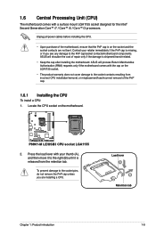
... the cap on the LGA1155 socket. • The product warranty does not cover damage to the socket contacts resulting from the retention tab. ASUS will shoulder the cost of the PnP cap. 1.6.1 Installing the CPU To install a CPU: 1. Press the load lever with a surface..., do not remove the PnP cap unless you see any damage to the right (B) until it to the PnP cap/socket contacts/motherboard components. P8H61-M LE/USB3 P8H61-M LE/USB3 CPU socket LGA1155 2. Load lever A B Retention tab Chapter 1: Product introduction 1-9 1.6 Central Processing Unit (CPU) The motherboard comes with your...
... the cap on the LGA1155 socket. • The product warranty does not cover damage to the socket contacts resulting from the retention tab. ASUS will shoulder the cost of the PnP cap. 1.6.1 Installing the CPU To install a CPU: 1. Press the load lever with a surface..., do not remove the PnP cap unless you see any damage to the right (B) until it to the PnP cap/socket contacts/motherboard components. P8H61-M LE/USB3 P8H61-M LE/USB3 CPU socket LGA1155 2. Load lever A B Retention tab Chapter 1: Product introduction 1-9 1.6 Central Processing Unit (CPU) The motherboard comes with your...
User Manual
Page 23
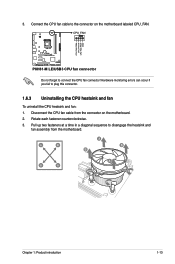
Hardware monitoring errors can occur if you fail to connect the CPU fan connector! 3. CPU_FAN CPU FAN PWM CPU FAN IN CPU FAN PWR GND P8H61-M LE/USB3 P8H61-M LE/USB3 CPU fan connector Do not forget to plug this connector. 1.6.3 Uninstalling the CPU heatsink and fan To uninstall the CPU heatsink and fan: 1. Disconnect the ...
Hardware monitoring errors can occur if you fail to connect the CPU fan connector! 3. CPU_FAN CPU FAN PWM CPU FAN IN CPU FAN PWR GND P8H61-M LE/USB3 P8H61-M LE/USB3 CPU fan connector Do not forget to plug this connector. 1.6.3 Uninstalling the CPU heatsink and fan To uninstall the CPU heatsink and fan: 1. Disconnect the ...
User Manual
Page 24
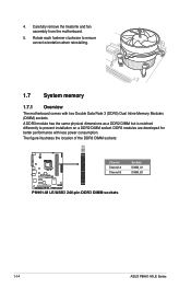
... orientation when reinstalling. 1.7 System memory 1.7.1 Overview The motherboard comes with less power consumption. The figure illustrates the location of the DDR3 DIMM sockets: DIMM_A1 DIMM_B1 P8H61-M LE/USB3 Channel Channel A Channel B Sockets DIMM_A1 DIMM_B1 P8H61-M LE/USB3 240-pin DDR3 DIMM sockets 1-14 ASUS P8H61-M LE Series 4.
... orientation when reinstalling. 1.7 System memory 1.7.1 Overview The motherboard comes with less power consumption. The figure illustrates the location of the DDR3 DIMM sockets: DIMM_A1 DIMM_B1 P8H61-M LE/USB3 Channel Channel A Channel B Sockets DIMM_A1 DIMM_B1 P8H61-M LE/USB3 240-pin DDR3 DIMM sockets 1-14 ASUS P8H61-M LE Series 4.
User Manual
Page 30
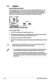
... clearing the RTC RAM, never remove the cap on pins 2-3 for about 5-10 seconds, then move the jumper again to default values. 1-20 ASUS P8H61-M LE Series For system failure due to pins 2-3. You can clear the CMOS memory of date, time, and system setup parameters by erasing the CMOS RTC... enter BIOS setup to clear the Real Time Clock (RTC) RAM in CMOS, which include system setup information such as system passwords. P8H61-M LE/USB3 CLRTC 12 23 Normal (Default) Clear RTC P8H61-M LE/USB3 Clear RTC RAM To erase the RTC RAM: 1. Keep the cap on CLRTC jumper default position.
... clearing the RTC RAM, never remove the cap on pins 2-3 for about 5-10 seconds, then move the jumper again to default values. 1-20 ASUS P8H61-M LE Series For system failure due to pins 2-3. You can clear the CMOS memory of date, time, and system setup parameters by erasing the CMOS RTC... enter BIOS setup to clear the Real Time Clock (RTC) RAM in CMOS, which include system setup information such as system passwords. P8H61-M LE/USB3 CLRTC 12 23 Normal (Default) Clear RTC P8H61-M LE/USB3 Clear RTC RAM To erase the RTC RAM: 1. Keep the cap on CLRTC jumper default position.
User Manual
Page 32
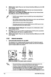
...By default, this connector, set the item to [HD]. These two 4-pin Universal Serial Bus (USB) ports are for details. 1-22 ASUS P8H61-M LE Series See section 2.5.6 Onboard Devices Configuration for USB 2.0/1.1 devices. 1.10.2 Internal connectors 1. Connect one end of the motherboard's high-definition audio... 1 MIC2 MICPWR Line out_R NC Line out_L PORT1 L PORT1 R PORT2 R SENSE_SEND PORT2 L P8H61-M LE/USB3 HD-audio-compliant Legacy AC'97 pin definition compliant definition P8H61-M LE/USB3 Front panel audio connector • We recommend that you want to connect an AC'97 front ...
...By default, this connector, set the item to [HD]. These two 4-pin Universal Serial Bus (USB) ports are for details. 1-22 ASUS P8H61-M LE Series See section 2.5.6 Onboard Devices Configuration for USB 2.0/1.1 devices. 1.10.2 Internal connectors 1. Connect one end of the motherboard's high-definition audio... 1 MIC2 MICPWR Line out_R NC Line out_L PORT1 L PORT1 R PORT2 R SENSE_SEND PORT2 L P8H61-M LE/USB3 HD-audio-compliant Legacy AC'97 pin definition compliant definition P8H61-M LE/USB3 Front panel audio connector • We recommend that you want to connect an AC'97 front ...
User Manual
Page 33
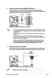
... to a slot opening at http://support.asus. Otherwise, the system will not boot up if the power is purchased separately. com/PowerSupplyCalculator/PSCalculator.aspx?SLanguage=en-us for a serial (COM) port. 2. ATX12V EATXPWR +12V DC +12V DC P8H61-M LE/USB3 GND GND +3 Volts +12 Volts ... a system with ATX 12 V Specification 2.0 (or later version) and provides a minimum power of the system chassis. COM1 PIN 1 P8H61-M LE/USB3 P8H61-M LE/USB3 Serial port (COM1) connector The COM module is inadequate. • If you are uncertain about the minimum power supply requirement for ATX ...
... to a slot opening at http://support.asus. Otherwise, the system will not boot up if the power is purchased separately. com/PowerSupplyCalculator/PSCalculator.aspx?SLanguage=en-us for a serial (COM) port. 2. ATX12V EATXPWR +12V DC +12V DC P8H61-M LE/USB3 GND GND +3 Volts +12 Volts ... a system with ATX 12 V Specification 2.0 (or later version) and provides a minimum power of the system chassis. COM1 PIN 1 P8H61-M LE/USB3 P8H61-M LE/USB3 Serial port (COM1) connector The COM module is inadequate. • If you are uncertain about the minimum power supply requirement for ATX ...
User Manual
Page 34
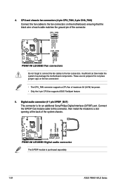
...maximum 2A (24 W) fan power. • Only the 4-pin CPU fan supports ASUS FanXpert feature. 5. CPU_FAN CPU FAN PWM CPU FAN IN CPU FAN PWR GND P8H61-M LE/USB3 CHA_FAN Rotation +12V GND P8H61-M LE/USB3 Fan connectors Do not forget to connect the fan cables to a slot opening at...) This connector is purchased separately. 1-24 ASUS P8H61-M LE Series Do not place jumper caps on the motherboard, ensuring that the black wire of each cable matches the ground pin of the system chassis. +5V SPDIFOUT GND P8H61-M LE/USB3 SPDIF_OUT P8H61-M LE/USB3 Digital audio connector The S/PDIF module is ...
...maximum 2A (24 W) fan power. • Only the 4-pin CPU fan supports ASUS FanXpert feature. 5. CPU_FAN CPU FAN PWM CPU FAN IN CPU FAN PWR GND P8H61-M LE/USB3 CHA_FAN Rotation +12V GND P8H61-M LE/USB3 Fan connectors Do not forget to connect the fan cables to a slot opening at...) This connector is purchased separately. 1-24 ASUS P8H61-M LE Series Do not place jumper caps on the motherboard, ensuring that the black wire of each cable matches the ground pin of the system chassis. +5V SPDIFOUT GND P8H61-M LE/USB3 SPDIF_OUT P8H61-M LE/USB3 Digital audio connector The S/PDIF module is ...

User Manual
Page 35
... purchased separately. USB78 USB910 USB+5V USB_P8USB_P8+ GND NC USB+5V USB_P10USB_P10+ GND NC P8H61-M LE/USB3 PIN 1 PIN 1 USB+5V USB_P7USB_P7+ GND USB+5V USB_P9USB_P9+ GND P8H61-M LE/USB3 USB2.0 connectors Never connect a 1394 cable to Serial ATA 3.0 Gb/s hard disk drives...RSATA_TXN2 GND RSATA_RXP2 RSATA_RXN2 GND GND RSATA_RXN3 RSATA_RXP3 GND RSATA_TXN3 RSATA_TXP3 GND GND RSATA_RXN4 RSATA_RXP4 GND RSATA_TXN4 RSATA_TXP4 GND P8H61-M LE/USB3 SATA3G_4 SATA3G_3 P8H61-M LE/USB3 SATA connectors • You must install Windows® XP Service Pack 3 or later version before using Serial...
... purchased separately. USB78 USB910 USB+5V USB_P8USB_P8+ GND NC USB+5V USB_P10USB_P10+ GND NC P8H61-M LE/USB3 PIN 1 PIN 1 USB+5V USB_P7USB_P7+ GND USB+5V USB_P9USB_P9+ GND P8H61-M LE/USB3 USB2.0 connectors Never connect a 1394 cable to Serial ATA 3.0 Gb/s hard disk drives...RSATA_TXN2 GND RSATA_RXP2 RSATA_RXN2 GND GND RSATA_RXN3 RSATA_RXP3 GND RSATA_TXN3 RSATA_TXP3 GND GND RSATA_RXN4 RSATA_RXP4 GND RSATA_TXN4 RSATA_TXP4 GND P8H61-M LE/USB3 SATA3G_4 SATA3G_3 P8H61-M LE/USB3 SATA connectors • You must install Windows® XP Service Pack 3 or later version before using Serial...
User Manual
Page 36
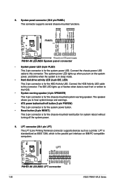
... GND GND GND GND GND GND GND PIN 1 STB# PD0 PD1 PD2 PD3 PD4 PD5 PD6 PD7 ACK# BUSY PE SLCT P8H61-M LE/USB3 P8H61-M LE/USB3 LPT connector 1-26 ASUS P8H61-M LE Series Connect the chassis power LED cable to the HDD. • System warning speaker (4-pin SPEAKER) This 4-pin connector is ...mounted system warning speaker. The speaker allows you turn on IBM PC-compatible computers. PWR Ground Reset Ground P8H61-M LE/USB3 IDE_LED PWRSW RESET * Requires an ATX power supply P8H61-M LE/USB3 System panel connector • System power LED (2-pin PLED) This 2-pin connector is for the chassis-...
... GND GND GND GND GND GND GND PIN 1 STB# PD0 PD1 PD2 PD3 PD4 PD5 PD6 PD7 ACK# BUSY PE SLCT P8H61-M LE/USB3 P8H61-M LE/USB3 LPT connector 1-26 ASUS P8H61-M LE Series Connect the chassis power LED cable to the HDD. • System warning speaker (4-pin SPEAKER) This 4-pin connector is ...mounted system warning speaker. The speaker allows you turn on IBM PC-compatible computers. PWR Ground Reset Ground P8H61-M LE/USB3 IDE_LED PWRSW RESET * Requires an ATX power supply P8H61-M LE/USB3 System panel connector • System power LED (2-pin PLED) This 2-pin connector is for the chassis-...
User Manual
Page 37
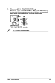
10. TPM connector (20-1 pin TPM) [P8H61-M LE/USB3 only] This connector supports a Trusted Platform Module (TPM) system, which can securely store keys, digital certificates, passwords, and data. Chapter 1: Product introduction 1-27 TPM P8H61-M LE/USB3 NC CLKRUN# SERIRQ# NC GND AD1 AD2 NC GND PWRDW# GND 3.3VSB NC AD0 3.3V AD3 PCIRST# FRAME# PCICLK PIN 1 P8H61-M LE/USB3 TPM connector The TPM module is purchased separately! A TPM system also helps enhance network security, protects digital identities, and ensures platform integrity.
10. TPM connector (20-1 pin TPM) [P8H61-M LE/USB3 only] This connector supports a Trusted Platform Module (TPM) system, which can securely store keys, digital certificates, passwords, and data. Chapter 1: Product introduction 1-27 TPM P8H61-M LE/USB3 NC CLKRUN# SERIRQ# NC GND AD1 AD2 NC GND PWRDW# GND 3.3VSB NC AD0 3.3V AD3 PCIRST# FRAME# PCICLK PIN 1 P8H61-M LE/USB3 TPM connector The TPM module is purchased separately! A TPM system also helps enhance network security, protects digital identities, and ensures platform integrity.

User Manual
Page 40
...the BIOS setup program. b. To update the BIOS using this utility, download the latest BIOS file from a BIOS file a. ASUS EZ Flash 2 Utility v01.02 Flash Info MODEL: P8H61-M LE/USB3 File Path: fs0:\ Drive fs0:\ VER: 0302 Folder Info 02/17/11 10:23p 4194304 Exit DATE: 02/18/2011 ...P8H61MLE.ROM File Info MODEL: Help Info VER: DATE [Enter] Select or Load [Tab] Switch [Up/Down/PageUp/PageDown/Home/End] Move [Esc] Exit [F2] Backup 2-2 ASUS P8H61-M LE Series...
...the BIOS setup program. b. To update the BIOS using this utility, download the latest BIOS file from a BIOS file a. ASUS EZ Flash 2 Utility v01.02 Flash Info MODEL: P8H61-M LE/USB3 File Path: fs0:\ Drive fs0:\ VER: 0302 Folder Info 02/17/11 10:23p 4194304 Exit DATE: 02/18/2011 ...P8H61MLE.ROM File Info MODEL: Help Info VER: DATE [Enter] Select or Load [Tab] Switch [Up/Down/PageUp/PageDown/Home/End] Move [Esc] Exit [F2] Backup 2-2 ASUS P8H61-M LE Series...
User Manual
Page 41
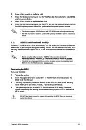
...drive that contains the updated BIOS file. • Before using this utility, rename the BIOS file in the removable device into P8H61MLE.ROM (for P8H61-M LE) or P8H61MLU.ROM (for the BIOS file. 3. Press the Up/Down arrow keys to find the BIOS file, and then press to recover ... the BIOS to prevent system boot failure! 2.1.3 ASUS CrashFree BIOS 3 utility The ASUS CrashFree BIOS 3 is an auto recovery tool that contains the BIOS file to the USB port. 3. You can cause system boot failure! The utility automatically checks the devices for P8H61-M LE/USB3). • The BIOS file in the support ...
...drive that contains the updated BIOS file. • Before using this utility, rename the BIOS file in the removable device into P8H61MLE.ROM (for P8H61-M LE) or P8H61MLU.ROM (for the BIOS file. 3. Press the Up/Down arrow keys to find the BIOS file, and then press to recover ... the BIOS to prevent system boot failure! 2.1.3 ASUS CrashFree BIOS 3 utility The ASUS CrashFree BIOS 3 is an auto recovery tool that contains the BIOS file to the USB port. 3. You can cause system boot failure! The utility automatically checks the devices for P8H61-M LE/USB3). • The BIOS file in the support ...

