
User Manual
Page 11
... pad or in the bag that came with a standby power LED that lights up to page x for buying an ASUS® P8H61-I Onboard LED 1-1 Chapter 1: Product introduction SB_PWR P8H61-I ON OFF Standby Power Powered Off P8H61-I motherboard! Chapter 1 Product introduction Thank you for the list of accessories. Onboard LED This motherboard comes with the...
... pad or in the bag that came with a standby power LED that lights up to page x for buying an ASUS® P8H61-I Onboard LED 1-1 Chapter 1: Product introduction SB_PWR P8H61-I ON OFF Standby Power Powered Off P8H61-I motherboard! Chapter 1 Product introduction Thank you for the list of accessories. Onboard LED This motherboard comes with the...

User Manual
Page 12
... USB1112) 2. The edge with external ports goes to the chassis. DO NOT overtighten the screws! Front panel audio connector (10-1 pin AAFP) 1-16 1-3 ASUS P8H61-I USB34 ASM 1042 LAN1_USB3_12 AUDIO RTL 8111E AAFP VIA VT1708S SPDIF_OUT LGA1155 EPU PCI1EX16 2 F_PANEL 7 SB_PWR 8 CLRTC 11 10 9 Place four screws into the ... Cell CMOS Power ATX12V EATXPWR 17.1cm(6.75in) DDR3 DIMM_B1 (64bit, 240-pin module) DDR3 DIMM_A1 (64bit, 240-pin module) DVI_VGA P8H61-I 1-2 CPU and chassis fan connectors (4-pin CPU_FAN, 4-pin CHA_FAN) 6. Standby power LED (SB_PWR) 1-1 1-3 9.
... USB1112) 2. The edge with external ports goes to the chassis. DO NOT overtighten the screws! Front panel audio connector (10-1 pin AAFP) 1-16 1-3 ASUS P8H61-I USB34 ASM 1042 LAN1_USB3_12 AUDIO RTL 8111E AAFP VIA VT1708S SPDIF_OUT LGA1155 EPU PCI1EX16 2 F_PANEL 7 SB_PWR 8 CLRTC 11 10 9 Place four screws into the ... Cell CMOS Power ATX12V EATXPWR 17.1cm(6.75in) DDR3 DIMM_B1 (64bit, 240-pin module) DDR3 DIMM_A1 (64bit, 240-pin module) DVI_VGA P8H61-I 1-2 CPU and chassis fan connectors (4-pin CPU_FAN, 4-pin CHA_FAN) 6. Standby power LED (SB_PWR) 1-1 1-3 9.

User Manual
Page 14
... 512Mb (64MB) chips or less. • The default memory operation frequency is then mapped for overclocking may install varying memory sizes in Channel A and Channel B. ASUS P8H61-I 1-4 To operate at the vendor-marked or at a lower frequency than the vendor-marked value. Under the default state, some memory modules for single-channel...
... 512Mb (64MB) chips or less. • The default memory operation frequency is then mapped for overclocking may install varying memory sizes in Channel A and Channel B. ASUS P8H61-I 1-4 To operate at the vendor-marked or at a lower frequency than the vendor-marked value. Under the default state, some memory modules for single-channel...

User Manual
Page 18
... system unstable and the card inoperable. 1.5.3 PCI Express x16 slot This motherboard has a PCI Express 2.0 x16 slot that they support. See Chapter 2 for later use . ASUS P8H61-I 1-8 Failure to do not need to the card. 3. Assign an IRQ to install expansion cards. 1.5 Expansion slots In the future, you may cause you physical...
... system unstable and the card inoperable. 1.5.3 PCI Express x16 slot This motherboard has a PCI Express 2.0 x16 slot that they support. See Chapter 2 for later use . ASUS P8H61-I 1-8 Failure to do not need to the card. 3. Assign an IRQ to install expansion cards. 1.5 Expansion slots In the future, you may cause you physical...

User Manual
Page 20
.... 2. This port is for the LAN port LED indications. Line In port (light blue). This port connects to a Local Area Network (LAN) through a network hub. ASUS P8H61-I 1-10 1.7 Connectors 1.7.1 1 Rear panel connectors 2 3 45 11 10 9 8 7 6 1. This 15-pin port is for the function of this port becomes Front Speaker Out. 6. Video Graphics...
.... 2. This port is for the LAN port LED indications. Line In port (light blue). This port connects to a Local Area Network (LAN) through a network hub. ASUS P8H61-I 1-10 1.7 Connectors 1.7.1 1 Rear panel connectors 2 3 45 11 10 9 8 7 6 1. This 15-pin port is for the function of this port becomes Front Speaker Out. 6. Video Graphics...

User Manual
Page 22
ATX power connectors (24-pin EATXPWR, 4-pin ATX12V) These connectors are for details. ASUS P8H61-I ATX power connectors GND +5 Volts +5 Volts +5 Volts -5 Volts GND GND GND PSON# GND -12 Volts +3 Volts • For a fully configured system, we recommend...DC +12V DC +3 Volts +12 Volts +12 Volts +5V Standby Power OK PIN 1 GND +5 Volts GND +5 Volts GND +3 Volts +3 Volts PIN 1 GND GND P8H61-I P8H61-I 1-12 1.7.2 Internal connectors 1. The power supply plugs are uncertain about the minimum power supply requirement for your system, refer to connect the 4-pin ATX +12V...
ATX power connectors (24-pin EATXPWR, 4-pin ATX12V) These connectors are for details. ASUS P8H61-I ATX power connectors GND +5 Volts +5 Volts +5 Volts -5 Volts GND GND GND PSON# GND -12 Volts +3 Volts • For a fully configured system, we recommend...DC +12V DC +3 Volts +12 Volts +12 Volts +5V Standby Power OK PIN 1 GND +5 Volts GND +5 Volts GND +3 Volts +3 Volts PIN 1 GND GND P8H61-I P8H61-I 1-12 1.7.2 Internal connectors 1. The power supply plugs are uncertain about the minimum power supply requirement for your system, refer to connect the 4-pin ATX +12V...

User Manual
Page 24
.../2/3/4 [blue]) These connectors connect to [AHCI Mode]. GND RSATA_RXN1 RSATA_RXP1 GND RSATA_TXN1 RSATA_TXP1 GND GND RSATA_TXP2 RSATA_TXN2 GND RSATA_RXP2 RSATA_RXN2 GND 4. SATA1 SATA2 SATA3 SATA4 P8H61-I 1-14 GND RSATA_TXP3 RSATA_TXN3 GND RSATA_RXP3 RSATA_RXN3 GND P8H61-I GND RSATA_TXP4 RSATA_TXN4 GND RSATA_RXP4 RSATA_RXN4 GND ASUS P8H61-I SATA connectors • When using Serial ATA.
.../2/3/4 [blue]) These connectors connect to [AHCI Mode]. GND RSATA_RXN1 RSATA_RXP1 GND RSATA_TXN1 RSATA_TXP1 GND GND RSATA_TXP2 RSATA_TXN2 GND RSATA_RXP2 RSATA_RXN2 GND 4. SATA1 SATA2 SATA3 SATA4 P8H61-I 1-14 GND RSATA_TXP3 RSATA_TXN3 GND RSATA_RXP3 RSATA_RXN3 GND P8H61-I GND RSATA_TXP4 RSATA_TXN4 GND RSATA_RXP4 RSATA_RXN4 GND ASUS P8H61-I SATA connectors • When using Serial ATA.
User Manual
Page 26
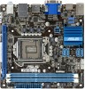
...USB1112 PIN 1 USB+5V USB_P11USB_P11+ GND USB+5V USB_P12USB_P12+ GND NC USB910 PIN 1 USB+5V USB_P9USB_P9+ GND USB+5V USB_P10USB_P10+ GND NC P8H61-I P8H61-I Front panel audio connector • We recommend that supports either HD Audio or legacy AC`97 audio standard. GND PRESENCE# SENSE1_RETUR SENSE2_RETUR AGND NC... an AC'97 front panel audio module to this connector is purchased separately. 7. By default, this connector, set to [HD]. 6. ASUS P8H61-I /O module that you connect a high-definition front panel audio module to this connector to avail of the system chassis.
...USB1112 PIN 1 USB+5V USB_P11USB_P11+ GND USB+5V USB_P12USB_P12+ GND NC USB910 PIN 1 USB+5V USB_P9USB_P9+ GND USB+5V USB_P10USB_P10+ GND NC P8H61-I P8H61-I Front panel audio connector • We recommend that supports either HD Audio or legacy AC`97 audio standard. GND PRESENCE# SENSE1_RETUR SENSE2_RETUR AGND NC... an AC'97 front panel audio module to this connector is purchased separately. 7. By default, this connector, set to [HD]. 6. ASUS P8H61-I /O module that you connect a high-definition front panel audio module to this connector to avail of the system chassis.

User Manual
Page 28
... magazines, e-books, as well as a value-added service for all ASUS products. Install ASUS @Vibe from the motherboard support DVD. 2. Launching ASUS @Vibe 1. To launch ASUS @Vibe ,click Start > All Programs > ASUS > ASUS VIBE > ASUS VIBE. 1.8.3 ASUS @Vibe ASUS @Vibe is a one-stop entertainment platform that serves as tune into ... and stream live TV anytime and anywhere. • The ASUS @Vibe service contents differ for each territory. • This utility does not work on Windows® 64-bit XP OS. Visit the ASUS website at www.asusvibe.com for more details. ASUS P8H61-I 1-18
... magazines, e-books, as well as a value-added service for all ASUS products. Install ASUS @Vibe from the motherboard support DVD. 2. Launching ASUS @Vibe 1. To launch ASUS @Vibe ,click Start > All Programs > ASUS > ASUS VIBE > ASUS VIBE. 1.8.3 ASUS @Vibe ASUS @Vibe is a one-stop entertainment platform that serves as tune into ... and stream live TV anytime and anywhere. • The ASUS @Vibe service contents differ for each territory. • This utility does not work on Windows® 64-bit XP OS. Visit the ASUS website at www.asusvibe.com for more details. ASUS P8H61-I 1-18
User Manual
Page 30
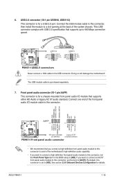
...-I Help Info VER: 0306 DATE: 01/14/11 [Enter] Select or Load [Tab] Switch [Up/Down/PageUp/PageDown/Home/End] Move [Esc] Exit [F2] Backup 2-2 ASUS P8H61-I Select Update BIOS from the Open window, then click Open. 3. Follow the onscreen instructions to the USB port. 2. Locate the BIOS file from file, then...
...-I Help Info VER: 0306 DATE: 01/14/11 [Enter] Select or Load [Tab] Switch [Up/Down/PageUp/PageDown/Home/End] Move [Esc] Exit [F2] Backup 2-2 ASUS P8H61-I Select Update BIOS from the Open window, then click Open. 3. Follow the onscreen instructions to the USB port. 2. Locate the BIOS file from file, then...

User Manual
Page 32
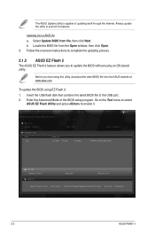
...defaults 3. Do not save them on the USB flash drive. 2.1.4 ASUS BIOS Updater The ASUS BIOS Updater allows you can use as a backup when the BIOS fails or gets corrupted during the updating process. C:\>d: D:\> 2-4 ASUS P8H61-I Before updating BIOS 1. At the FreeDOS prompt, type d: and press... to switch the disk from the ASUS website at http://support.asus.com and save the BIOS file and BIOS Updater to update BIOS in...
...defaults 3. Do not save them on the USB flash drive. 2.1.4 ASUS BIOS Updater The ASUS BIOS Updater allows you can use as a backup when the BIOS fails or gets corrupted during the updating process. C:\>d: D:\> 2-4 ASUS P8H61-I Before updating BIOS 1. At the FreeDOS prompt, type d: and press... to switch the disk from the ASUS website at http://support.asus.com and save the BIOS file and BIOS Updater to update BIOS in...

User Manual
Page 34
... is done, press to select the BIOS file and press . Refer to the DOS prompt after updating the BIOS file if you have disconnected them. 2-6 ASUS P8H61-I VER: 0306 DATE: 01/18/2011 Update ROM BOARD: Unknown VER: Unknown DATE: Unknown PATH: A:\ A: PH61I.ROM 4194304 2011-01-04 17:30:48 Note... boot failure! • For BIOS Updater version 1.04 or later, the utility automatically exits to section 2.9 Exit menu for DOS V1.07 Current ROM BOARD: P8H61-I
... is done, press to select the BIOS file and press . Refer to the DOS prompt after updating the BIOS file if you have disconnected them. 2-6 ASUS P8H61-I VER: 0306 DATE: 01/18/2011 Update ROM BOARD: Unknown VER: Unknown DATE: Unknown PATH: A:\ A: PH61I.ROM 4194304 2011-01-04 17:30:48 Note... boot failure! • For BIOS Updater version 1.04 or later, the utility automatically exits to section 2.9 Exit menu for DOS V1.07 Current ROM BOARD: P8H61-I

User Manual
Page 36
... setup program EFI BIOS Utility - To access the Advanced Mode, click Exit/Advanced Mode, then select Advanced Mode. EZ Mode Thursday [01/13/2011] P8H61-I BIOS Version : 0306 CPU Type : Intel(R) Core (TM) i5-2500 CPU @ 3.30GHz Total Memory : 1024 MB (DDR3 1333MHz) Build Date ....248V System Performance Quiet Performance Boot Priority Energy Saving Normal Use the mouse to drag or keyboard to navigate to the system. 2-8 ASUS P8H61-I You can change modes from the Exit menu or from the Exit/Advanced Mode button in s��e�c�t�i�o�...
... setup program EFI BIOS Utility - To access the Advanced Mode, click Exit/Advanced Mode, then select Advanced Mode. EZ Mode Thursday [01/13/2011] P8H61-I BIOS Version : 0306 CPU Type : Intel(R) Core (TM) i5-2500 CPU @ 3.30GHz Total Memory : 1024 MB (DDR3 1333MHz) Build Date ....248V System Performance Quiet Performance Boot Priority Energy Saving Normal Use the mouse to drag or keyboard to navigate to the system. 2-8 ASUS P8H61-I You can change modes from the Exit menu or from the Exit/Advanced Mode button in s��e�c�t�i�o�...

User Manual
Page 38
... right corner of a field, select it and press or click on it to select items in the menu and change the value of options. 2-10 ASUS P8H61-I Use the navigation keys to display a list of the field opposite the item. Menu items The highlighted item on the menu bar displays the specific...
... right corner of a field, select it and press or click on it to select items in the menu and change the value of options. 2-10 ASUS P8H61-I Use the navigation keys to display a list of the field opposite the item. Menu items The highlighted item on the menu bar displays the specific...

User Manual
Page 40
..., key in the current password, then press . 3. After you clear the password, the Administrator Password item on top of the screen shows Not Installed. 2-12 ASUS P8H61-I Confirm the password when prompted. To set an administrator password: 1. Select the User Password item and press . 2. Confirm the password when prompted. Otherwise, you might...
..., key in the current password, then press . 3. After you clear the password, the Administrator Password item on top of the screen shows Not Installed. 2-12 ASUS P8H61-I Confirm the password when prompted. To set an administrator password: 1. Select the User Password item and press . 2. Confirm the password when prompted. Otherwise, you might...

User Manual
Page 42
... may cause the system to become unstable! If this happens, revert to the default settings. 2.4.6 CPU Power Management The sub-items in this function. 2-14 ASUS P8H61-I Use and keys or the numeric keypad to enable or disable the Enhanced Intel® SpeedStep Technology (EIST). [Disabled] Disables this menu allow you to...
... may cause the system to become unstable! If this happens, revert to the default settings. 2.4.6 CPU Power Management The sub-items in this function. 2-14 ASUS P8H61-I Use and keys or the numeric keypad to enable or disable the Enhanced Intel® SpeedStep Technology (EIST). [Disabled] Disables this menu allow you to...

User Manual
Page 44
... Monitor Boot Tool Trusted Computing (TPM) settings →←: Select Screen ↑↓: Select Item Enter: Select +/-: Change Opt. Copyright (C) 2010 American Megatrends, Inc. 2-16 ASUS P8H61-I The values range from 0.05V to 0.15V with a 0.05V interval. 2.4.11 VCCSA Voltage [Auto] Allows you to set the VCCIO voltage. F1: General Help F2...
... Monitor Boot Tool Trusted Computing (TPM) settings →←: Select Screen ↑↓: Select Item Enter: Select +/-: Change Opt. Copyright (C) 2010 American Megatrends, Inc. 2-16 ASUS P8H61-I The values range from 0.05V to 0.15V with a 0.05V interval. 2.4.11 VCCSA Voltage [Auto] Allows you to set the VCCIO voltage. F1: General Help F2...

User Manual
Page 46
... options: [Auto] [Disabled] [Enabled] CPU C6 Report [Auto] Allows you to enable or disable the Intel® Turbo Mode Technology. Configuration options: [Disabled] [Enabled] 2-18 ASUS P8H61-I Configuration options: [Disabled] [Enabled] 2.5.4 PCH Configuration The South Bridge menu allows you to enable or disable the C1E support function. Turbo Mode [Enabled] This item...
... options: [Auto] [Disabled] [Enabled] CPU C6 Report [Auto] Allows you to enable or disable the Intel® Turbo Mode Technology. Configuration options: [Disabled] [Enabled] 2-18 ASUS P8H61-I Configuration options: [Disabled] [Enabled] 2.5.4 PCH Configuration The South Bridge menu allows you to enable or disable the C1E support function. Turbo Mode [Enabled] This item...

User Manual
Page 48
... when you set the front panel audio connector (AAFP) mode to [Enabled]. [Enabled] Enables the Asmedia USB 3.0 battery charging function. [Disabled] Disables this function 2-20 ASUS P8H61-I Asmedia USB 3.0 Battery Charging Support [Disabled] This item appears only when the Asmedia USB 3.0 Controller item is set the HD Audio Controller item to legacy...
... when you set the front panel audio connector (AAFP) mode to [Enabled]. [Enabled] Enables the Asmedia USB 3.0 battery charging function. [Disabled] Disables this function 2-20 ASUS P8H61-I Asmedia USB 3.0 Battery Charging Support [Disabled] This item appears only when the Asmedia USB 3.0 Controller item is set the HD Audio Controller item to legacy...

User Manual
Page 50
... V Anti Surge Support Enabled Version 2.00.1201. Copyright (C) 2010 American Megatrends, Inc. Select Ignore if you do not wish to display the detected speed. 2-22 ASUS P8H61-I
... V Anti Surge Support Enabled Version 2.00.1201. Copyright (C) 2010 American Megatrends, Inc. Select Ignore if you do not wish to display the detected speed. 2-22 ASUS P8H61-I


