
User Manual
Page 1
P8H61-I Motherboard
P8H61-I Motherboard

User Manual
Page 3
Contents Notices...vi Safety information vii About this guide vii P8H61-I specifications summary ix Chapter 1 Product introduction 1.1 Before you proceed 1-1 1.2 Motherboard overview 1-2 1.2.1 Motherboard layout 1-2 1.2.2 Layout contents 1-2 1.3 Central Processing Unit (CPU 1-3 ... system 1-17 1.8.2 Support DVD information 1-17 1.8.3 ASUS @Vibe 1-18 Chapter 2 BIOS information 2.1 Managing and updating your BIOS 2-1 2.1.1 ASUS Update utility 2-1 2.1.2 ASUS EZ Flash 2 2-2 2.1.3 ASUS CrashFree BIOS 3 utility 2-3 2.1.4 ASUS BIOS Updater 2-4 2.2 BIOS setup program 2-7 2.3 Main...
Contents Notices...vi Safety information vii About this guide vii P8H61-I specifications summary ix Chapter 1 Product introduction 1.1 Before you proceed 1-1 1.2 Motherboard overview 1-2 1.2.1 Motherboard layout 1-2 1.2.2 Layout contents 1-2 1.3 Central Processing Unit (CPU 1-3 ... system 1-17 1.8.2 Support DVD information 1-17 1.8.3 ASUS @Vibe 1-18 Chapter 2 BIOS information 2.1 Managing and updating your BIOS 2-1 2.1.1 ASUS Update utility 2-1 2.1.2 ASUS EZ Flash 2 2-2 2.1.3 ASUS CrashFree BIOS 3 utility 2-3 2.1.4 ASUS BIOS Updater 2-4 2.2 BIOS setup program 2-7 2.3 Main...

User Manual
Page 6
...for radio noise emissions from that the product (electrical and electronic equipment) should not be placed in our products at ASUS REACH website at http://csr.asus.com/english/REACH.htm. Changes or modifications to this equipment does cause harmful interference to assure compliance with FCC regulations....crossed out wheeled bin indicates that the battery should not be determined by one or more of Communications. vi DO NOT throw the motherboard in municipal waste. This symbol of electronic products. This equipment has been tested and found to enable proper reuse of the FCC ...
...for radio noise emissions from that the product (electrical and electronic equipment) should not be placed in our products at ASUS REACH website at http://csr.asus.com/english/REACH.htm. Changes or modifications to this equipment does cause harmful interference to assure compliance with FCC regulations....crossed out wheeled bin indicates that the battery should not be determined by one or more of Communications. vi DO NOT throw the motherboard in municipal waste. This symbol of electronic products. This equipment has been tested and found to enable proper reuse of the FCC ...
User Manual
Page 7
...that your power supply is organized This guide contains the following parts: • Chapter 1: Product introduction This chapter describes the features of the motherboard and the new technology it supports. • Chapter 2: BIOS information This chapter tells how to change system settings through the BIOS Setup ... vii About this guide is set to the correct voltage in any damage, contact your area. Operation safety • Before installing the motherboard and adding devices on a stable surface. • If you detect any area where it may become wet. • Place the product...
...that your power supply is organized This guide contains the following parts: • Chapter 1: Product introduction This chapter describes the features of the motherboard and the new technology it supports. • Chapter 2: BIOS information This chapter tells how to change system settings through the BIOS Setup ... vii About this guide is set to the correct voltage in any damage, contact your area. Operation safety • Before installing the motherboard and adding devices on a stable surface. • If you detect any area where it may become wet. • Place the product...

User Manual
Page 11
... below shows the location of accessories. Failure to do so may cause severe damage to page x for buying an ASUS® P8H61-I Onboard LED 1-1 Chapter 1: Product introduction Chapter 1 Product introduction Thank you must shut down the system and unplug the... before you install motherboard components or change any motherboard settings. • Unplug the power cord from the power supply. SB_PWR P8H61-I ON OFF Standby Power Powered Off P8H61-I motherboard! Onboard LED This motherboard comes with the component. • Before you uninstall any motherboard component. This is...
... below shows the location of accessories. Failure to do so may cause severe damage to page x for buying an ASUS® P8H61-I Onboard LED 1-1 Chapter 1: Product introduction Chapter 1 Product introduction Thank you must shut down the system and unplug the... before you install motherboard components or change any motherboard settings. • Unplug the power cord from the power supply. SB_PWR P8H61-I ON OFF Standby Power Powered Off P8H61-I motherboard! Onboard LED This motherboard comes with the component. • Before you uninstall any motherboard component. This is...

User Manual
Page 12
...ASUS P8H61-I USB34 ASM 1042 LAN1_USB3_12 AUDIO RTL 8111E AAFP VIA VT1708S SPDIF_OUT LGA1155 EPU PCI1EX16 2 F_PANEL 7 SB_PWR 8 CLRTC 11 10 9 Place four screws into the chassis in the correct orientation. Intel® H61 Serial ATA 3.0Gb/s connectors (7-pin SATA3G_1/2/3/4) 5. DDR3 U-DIMM slots Page Connectors/Jumpers/Slots/LED Page 1-16 7. 1.2 1.2.1 Motherboard overview Motherboard... layout Ensure that you install the motherboard into the holes indicated by circles to secure the motherboard to the rear part...
...ASUS P8H61-I USB34 ASM 1042 LAN1_USB3_12 AUDIO RTL 8111E AAFP VIA VT1708S SPDIF_OUT LGA1155 EPU PCI1EX16 2 F_PANEL 7 SB_PWR 8 CLRTC 11 10 9 Place four screws into the chassis in the correct orientation. Intel® H61 Serial ATA 3.0Gb/s connectors (7-pin SATA3G_1/2/3/4) 5. DDR3 U-DIMM slots Page Connectors/Jumpers/Slots/LED Page 1-16 7. 1.2 1.2.1 Motherboard overview Motherboard... layout Ensure that you install the motherboard into the holes indicated by circles to secure the motherboard to the rear part...

User Manual
Page 13
...8226; Upon purchase of repair only if the damage is notched differently to the PnP cap/socket contacts/motherboard components. ASUS will shoulder the cost of the motherboard, ensure that the PnP cap is missing, or if you see any damage to prevent installation on ... to the socket contacts resulting from incorrect CPU installation/removal, or misplacement/loss/incorrect removal of the DDR3 DIMM sockets: DIMM_A1 DIMM_B1 P8H61-I P8H61-I 240-pin DDR3 DIMM sockets Channel Channel A Channel B Sockets DIMM_A1 DIMM_B1 1-3 Chapter 1: Product introduction The figure illustrates the location...
...8226; Upon purchase of repair only if the damage is notched differently to the PnP cap/socket contacts/motherboard components. ASUS will shoulder the cost of the motherboard, ensure that the PnP cap is missing, or if you see any damage to prevent installation on ... to the socket contacts resulting from incorrect CPU installation/removal, or misplacement/loss/incorrect removal of the DDR3 DIMM sockets: DIMM_A1 DIMM_B1 P8H61-I P8H61-I 240-pin DDR3 DIMM sockets Channel Channel A Channel B Sockets DIMM_A1 DIMM_B1 1-3 Chapter 1: Product introduction The figure illustrates the location...

User Manual
Page 14
...a lower frequency than the vendor-marked value. ASUS P8H61-I 1-4 Any excess memory from the same vendor. • Due to the memory address limitation on 32-bit Windows® OS, when you want to install 4GB or more on the motherboard. • This motherboard does not support DIMMs made up of 512Mb ...(64MB) chips or less. • The default memory operation frequency is dependent on the motherboard, the actual usable memory for overclocking may install varying memory sizes in Channel A and Channel B. For optimum compatibility, we recommend that ...
...a lower frequency than the vendor-marked value. ASUS P8H61-I 1-4 Any excess memory from the same vendor. • Due to the memory address limitation on 32-bit Windows® OS, when you want to install 4GB or more on the motherboard. • This motherboard does not support DIMMs made up of 512Mb ...(64MB) chips or less. • The default memory operation frequency is dependent on the motherboard, the actual usable memory for overclocking may install varying memory sizes in Channel A and Channel B. For optimum compatibility, we recommend that ...

User Manual
Page 18
..., conflicts will arise between the two PCI groups, making the system unstable and the card inoperable. 1.5.3 PCI Express x16 slot This motherboard has a PCI Express 2.0 x16 slot that the cards do so may need IRQ assignments. The following sub‑sections describe the ...later use . ASUS P8H61-I 1-8 Unplug the power cord before adding or removing expansion cards. Turn on BIOS setup. 2. Secure the card to install expansion cards. Assign an IRQ to use . 4. 1.5 Expansion slots In the future, you may cause you physical injury and damage motherboard components. 1.5.1...
..., conflicts will arise between the two PCI groups, making the system unstable and the card inoperable. 1.5.3 PCI Express x16 slot This motherboard has a PCI Express 2.0 x16 slot that the cards do so may need IRQ assignments. The following sub‑sections describe the ...later use . ASUS P8H61-I 1-8 Unplug the power cord before adding or removing expansion cards. Turn on BIOS setup. 2. Secure the card to install expansion cards. Assign an IRQ to use . 4. 1.5 Expansion slots In the future, you may cause you physical injury and damage motherboard components. 1.5.1...

User Manual
Page 23
... inside the system may damage the motherboard components. Connect the S/PDIF Out module cable to this connector, then install the module to a slot opening at the back of the connector. Only the 4-pin CPU fan and chassis fan support the ASUS FanXpert feature. 3. P8H61-I +5V SPDIFOUT GND 1-13 Chapter...CHASSIS FAN IN CHA FAN PWR GND 2. CPU_FAN CHA_FAN P8H61-I Digital audio connector The S/PDIF module is for an additional Sony/Philips Digital Interface (S/PDIF) port. These are not jumpers! Do not place jumper caps on the motherboard, ensuring that the black wire of each cable matches...
... inside the system may damage the motherboard components. Connect the S/PDIF Out module cable to this connector, then install the module to a slot opening at the back of the connector. Only the 4-pin CPU fan and chassis fan support the ASUS FanXpert feature. 3. P8H61-I +5V SPDIFOUT GND 1-13 Chapter...CHASSIS FAN IN CHA FAN PWR GND 2. CPU_FAN CHA_FAN P8H61-I Digital audio connector The S/PDIF module is for an additional Sony/Philips Digital Interface (S/PDIF) port. These are not jumpers! Do not place jumper caps on the motherboard, ensuring that the black wire of each cable matches...
User Manual
Page 26
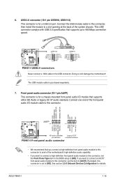
...complys with USB 2.0 specification that you connect a high-definition front panel audio module to this connector to avail of the motherboard's high-definition audio capability. • If you want to connect a high-definition front panel audio module to this connector...1 MIC2 MICPWR Line out_R NC Line out_L PORT1 L PORT1 R PORT2 R SENSE_SEND PORT2 L P8H61-I HD-audio-compliant Legacy AC'97 pin definition compliant definition P8H61-I 1-16 Doing so will damage the motherboard! ASUS P8H61-I Front panel audio connector • We recommend that supports up to [AC97]. Front panel ...
...complys with USB 2.0 specification that you connect a high-definition front panel audio module to this connector to avail of the motherboard's high-definition audio capability. • If you want to connect a high-definition front panel audio module to this connector...1 MIC2 MICPWR Line out_R NC Line out_L PORT1 L PORT1 R PORT2 R SENSE_SEND PORT2 L P8H61-I HD-audio-compliant Legacy AC'97 pin definition compliant definition P8H61-I 1-16 Doing so will damage the motherboard! ASUS P8H61-I Front panel audio connector • We recommend that supports up to [AC97]. Front panel ...

User Manual
Page 27
The contents of the Support DVD are subject to change at www.asus.com for updates. Click an icon to display Support DVD/ motherboard information Click an item to the optical drive. Refer to your OS documentation for detailed information. • Ensure that you install Windows&#... software applications, and utilities that you can install to locate the file ASSETUP.EXE from the BIN folder. Visit the ASUS website at any time without notice. Always install the latest OS version and corresponding updates to maximize the features of the Support DVD to avail all motherboard features.
The contents of the Support DVD are subject to change at www.asus.com for updates. Click an icon to display Support DVD/ motherboard information Click an item to the optical drive. Refer to your OS documentation for detailed information. • Ensure that you install Windows&#... software applications, and utilities that you can install to locate the file ASSETUP.EXE from the BIN folder. Visit the ASUS website at any time without notice. Always install the latest OS version and corresponding updates to maximize the features of the Support DVD to avail all motherboard features.

User Manual
Page 28
... such as music, videos, games, magazines, e-books, as well as a value-added service for all ASUS products. To launch ASUS @Vibe ,click Start > All Programs > ASUS > ASUS VIBE > ASUS VIBE. Launching ASUS @Vibe 1. Install ASUS @Vibe from the motherboard support DVD. 2. ASUS P8H61-I 1-18 1.8.3 ASUS @Vibe ASUS @Vibe is a one-stop entertainment platform that serves as tune into your favorite radio stations...
... such as music, videos, games, magazines, e-books, as well as a value-added service for all ASUS products. To launch ASUS @Vibe ,click Start > All Programs > ASUS > ASUS VIBE > ASUS VIBE. Launching ASUS @Vibe 1. Install ASUS @Vibe from the motherboard support DVD. 2. ASUS P8H61-I 1-18 1.8.3 ASUS @Vibe ASUS @Vibe is a one-stop entertainment platform that serves as tune into your favorite radio stations...

User Manual
Page 29
..., select the BIOS version that you wish to manage, save, and update the motherboard BIOS in Windows® environment. • ASUS Update requires an Internet connection either of the original motherboard BIOS file to a USB flash disk in the support DVD that allows you to...an Internet Service Provider (ISP). • This utility is a utility that comes with the motherboard package. Installing ASUS Update To install ASUS Update: 1. Click Update button from the Quick Bar, and then click ASUS Update from the Internet, then click Next. c. The Drivers menu appears. 2. Click the...
..., select the BIOS version that you wish to manage, save, and update the motherboard BIOS in Windows® environment. • ASUS Update requires an Internet connection either of the original motherboard BIOS file to a USB flash disk in the support DVD that allows you to...an Internet Service Provider (ISP). • This utility is a utility that comes with the motherboard package. Installing ASUS Update To install ASUS Update: 1. Click Update button from the Quick Bar, and then click ASUS Update from the Internet, then click Next. c. The Drivers menu appears. 2. Click the...

User Manual
Page 31
...support DVD may not be the latest version. Recovering the BIOS To recover the BIOS: 1. Doing so can restore a corrupted BIOS file using the motherboard support DVD or a USB flash drive that contains the BIOS file to the Drive field. 4. Press to switch to the USB port. 3. ...corrupted during the updating process. The utility automatically checks the devices for the BIOS file. When found, the utility reads the BIOS file and enters ASUS EZ Flash 2 utility automatically. 4. To ensure system compatibility and stability, we recommend that allows you to the Folder Info field. 6. DO ...
...support DVD may not be the latest version. Recovering the BIOS To recover the BIOS: 1. Doing so can restore a corrupted BIOS file using the motherboard support DVD or a USB flash drive that contains the BIOS file to the Drive field. 4. Press to switch to the USB port. 3. ...corrupted during the updating process. The utility automatically checks the devices for the BIOS file. When found, the utility reads the BIOS file and enters ASUS EZ Flash 2 utility automatically. 4. To ensure system compatibility and stability, we recommend that allows you to the Folder Info field. 6. DO ...

User Manual
Page 32
.../16 format and single partition. 2. Insert the support DVD into the optical drive and select the optical drive as shown. Prepare the motherboard support DVD and a USB flash drive in DOS environment 1. Insert the USB flash drive with the latest BIOS file and BIOS Updater...Make Disk menu appears, select the FreeDOS command prompt item by pressing the item number. 4. Before updating BIOS 1. Boot your computer. C:\>d: D:\> 2-4 ASUS P8H61-I This utility also allows you to copy the current BIOS file that you to a hard disk drive or USB flash drive in DOS environment. The...
.../16 format and single partition. 2. Insert the support DVD into the optical drive and select the optical drive as shown. Prepare the motherboard support DVD and a USB flash drive in DOS environment 1. Insert the USB flash drive with the latest BIOS file and BIOS Updater...Make Disk menu appears, select the FreeDOS command prompt item by pressing the item number. 4. Before updating BIOS 1. Boot your computer. C:\>d: D:\> 2-4 ASUS P8H61-I This utility also allows you to copy the current BIOS file that you to a hard disk drive or USB flash drive in DOS environment. The...
User Manual
Page 35
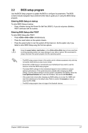
...Menu. Entering BIOS Setup at startup To enter BIOS Setup at startup: • Press during the Power-On Self Test (POST). Do this motherboard apply for most conditions to ensure optimum performance. If the system becomes unstable after changing any BIOS settings, load the default settings to guide ... 2.9 Exit Menu. • If the system fails to boot after changing any BIOS setting, try to clear the CMOS and reset the motherboard to your motherboard if you want to use the mouse to control the BIOS setup program. • The default BIOS settings for reference purposes only, and may...
...Menu. Entering BIOS Setup at startup To enter BIOS Setup at startup: • Press during the Power-On Self Test (POST). Do this motherboard apply for most conditions to ensure optimum performance. If the system becomes unstable after changing any BIOS settings, load the default settings to guide ... 2.9 Exit Menu. • If the system fails to boot after changing any BIOS setting, try to clear the CMOS and reset the motherboard to your motherboard if you want to use the mouse to control the BIOS setup program. • The default BIOS settings for reference purposes only, and may...

User Manual
Page 36
...Exits the BIOS setup program without saving the changes, saves the changes and resets the system, or enters the Advanced Mode Displays the CPU/motherboard temperature, CPU/5V/3.3V/12V voltage Selects the display language of the basic system information, and allows you to select the display language, ... appears when you installed to the system. • The Boot Menu(F8) button is available only when the boot device is installed to the system. 2-8 ASUS P8H61-I BIOS Version : 0306 CPU Type : Intel(R) Core (TM) i5-2500 CPU @ 3.30GHz Total Memory : 1024 MB (DDR3 1333MHz) Build Date : 01/18/...
...Exits the BIOS setup program without saving the changes, saves the changes and resets the system, or enters the Advanced Mode Displays the CPU/motherboard temperature, CPU/5V/3.3V/12V voltage Selects the display language of the basic system information, and allows you to select the display language, ... appears when you installed to the system. • The Boot Menu(F8) button is available only when the boot device is installed to the system. 2-8 ASUS P8H61-I BIOS Version : 0306 CPU Type : Intel(R) Core (TM) i5-2500 CPU @ 3.30GHz Total Memory : 1024 MB (DDR3 1333MHz) Build Date : 01/18/...

User Manual
Page 41
... on the CPU and DIMM model you use X.M.P. Configuration options: [Auto] [X.M.P.] Chapter 2: BIOS information 2-13 The configuration options for this section vary depending on the motherboard. EFI BIOS Utility - F1: General Help F2: Previous Values F5: Optimized Defaults F10: Save ESC: Exit Version 2.00.1201. Copyright (C) 2010 American Megatrends, Inc. Frequency...
... on the CPU and DIMM model you use X.M.P. Configuration options: [Auto] [X.M.P.] Chapter 2: BIOS information 2-13 The configuration options for this section vary depending on the motherboard. EFI BIOS Utility - F1: General Help F2: Previous Values F5: Optimized Defaults F10: Save ESC: Exit Version 2.00.1201. Copyright (C) 2010 American Megatrends, Inc. Frequency...
User Manual
Page 45
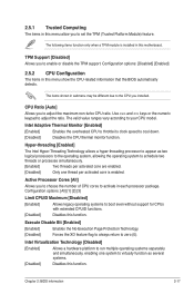
... adjust the ratio. Use and keys or the numeric keypad to cool down. [Disabled] Disables the CPU thermal monitor function. The items shown in this motherboard. Hyper-threading [Enabled] The Intel Hyper-Threading Technology allows a hyper-threading processor to appear as two logical processors to the operating system, allowing the operating...
... adjust the ratio. Use and keys or the numeric keypad to cool down. [Disabled] Disables the CPU thermal monitor function. The items shown in this motherboard. Hyper-threading [Enabled] The Intel Hyper-Threading Technology allows a hyper-threading processor to appear as two logical processors to the operating system, allowing the operating...


