
User Manual
Page 12
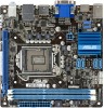
...(7-pin SATA3G_1/2/3/4) 5. System panel connector (10-1 pin F_PANEL) 1-15 1-12 8. Front panel audio connector (10-1 pin AAFP) 1-16 1-3 ASUS P8H61-I USB34 ASM 1042 LAN1_USB3_12 AUDIO RTL 8111E AAFP VIA VT1708S SPDIF_OUT LGA1155 EPU PCI1EX16 2 F_PANEL 7 SB_PWR 8 CLRTC 11 10 9 Place four screws... into the chassis in the correct orientation. CPU and chassis fan connectors (4-pin CPU_FAN, 4-pin CHA_FAN) 6. Clear RTC RAM (3-pin CLRTC) 1-9 1-14 10. Digital audio connector (4-1 pin SPDIF_OUT) 1-13 1-13 11. Doing so can damage the motherboard. 1.2.2 ...
...(7-pin SATA3G_1/2/3/4) 5. System panel connector (10-1 pin F_PANEL) 1-15 1-12 8. Front panel audio connector (10-1 pin AAFP) 1-16 1-3 ASUS P8H61-I USB34 ASM 1042 LAN1_USB3_12 AUDIO RTL 8111E AAFP VIA VT1708S SPDIF_OUT LGA1155 EPU PCI1EX16 2 F_PANEL 7 SB_PWR 8 CLRTC 11 10 9 Place four screws... into the chassis in the correct orientation. CPU and chassis fan connectors (4-pin CPU_FAN, 4-pin CHA_FAN) 6. Clear RTC RAM (3-pin CLRTC) 1-9 1-14 10. Digital audio connector (4-1 pin SPDIF_OUT) 1-13 1-13 11. Doing so can damage the motherboard. 1.2.2 ...
User Manual
Page 19
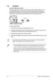
... clearing the CMOS, reinstall the battery. • You do not help, remove the onboard battery and move the cap back to clear the CMOS RTC RAM data. Keep the cap on CLRTC jumper default position. CLRTC 12 23 P8H61-I Normal (Default) P8H61-I Clear RTC RAM Clear RTC To erase the RTC...
... clearing the CMOS, reinstall the battery. • You do not help, remove the onboard battery and move the cap back to clear the CMOS RTC RAM data. Keep the cap on CLRTC jumper default position. CLRTC 12 23 P8H61-I Normal (Default) P8H61-I Clear RTC RAM Clear RTC To erase the RTC...
User Manual
Page 35
... the operating system. • The BIOS setup screens shown in using the first two options. Refer to section 1.6 Jumpers on how to erase the RTC RAM. • The BIOS setup program does not support the bluetooth devices. If you failed to enter BIOS Setup using the BIOS Setup program. 2.2 BIOS setup...
... the operating system. • The BIOS setup screens shown in using the first two options. Refer to section 1.6 Jumpers on how to erase the RTC RAM. • The BIOS setup program does not support the bluetooth devices. If you failed to enter BIOS Setup using the BIOS Setup program. 2.2 BIOS setup...

User Manual
Page 39
... menu items allow you to change the system security settings. • If you have forgotten your BIOS password, erase the CMOS Real Time Clock (RTC) RAM to set a password, these items show the default Not Installed. The Main menu provides you an overview of the screen show Installed. EFI BIOS Utility... you to clear the BIOS password. See section 1.6 Jumpers for information on top of the basic system information, and allows you to erase the RTC RAM. • The Administrator or User Password items on how to choose the BIOS language version from the options.
... menu items allow you to change the system security settings. • If you have forgotten your BIOS password, erase the CMOS Real Time Clock (RTC) RAM to set a password, these items show the default Not Installed. The Main menu provides you an overview of the screen show Installed. EFI BIOS Utility... you to clear the BIOS password. See section 1.6 Jumpers for information on top of the basic system information, and allows you to erase the RTC RAM. • The Administrator or User Password items on how to choose the BIOS language version from the options.


