
P8H61-I R2.0 User's Manual
Page 1
Motherboard P8H61-I R2.0
Motherboard P8H61-I R2.0
P8H61-I R2.0 User's Manual
Page 3
Contents Safety information vi About this guide vi P8H61-I R2.0 specifications summary viii Chapter 1 Product introduction 1.1 Before you proceed 1-1 1.2 Motherboard overview 1-2 1.2.1 Placement direction 1-2 1.2.2 Screw holes 1-2 1.2.3 Motherboard layout 1-3 1.2.4 Layout contents 1-3 1.3 Central ...support 1-22 1.8.1 Installing an operating system 1-22 1.8.2 Support DVD information 1-22 Chapter 2 BIOS information 2.1 Managing and updating your BIOS 2-1 2.1.1 ASUS Update utility 2-1 2.1.2 ASUS EZ Flash 2 2-2 2.1.3 ASUS CrashFree BIOS 3 utility 2-3 2.1.4 ASUS BIOS Updater 2-4 iii
Contents Safety information vi About this guide vi P8H61-I R2.0 specifications summary viii Chapter 1 Product introduction 1.1 Before you proceed 1-1 1.2 Motherboard overview 1-2 1.2.1 Placement direction 1-2 1.2.2 Screw holes 1-2 1.2.3 Motherboard layout 1-3 1.2.4 Layout contents 1-3 1.3 Central ...support 1-22 1.8.1 Installing an operating system 1-22 1.8.2 Support DVD information 1-22 Chapter 2 BIOS information 2.1 Managing and updating your BIOS 2-1 2.1.1 ASUS Update utility 2-1 2.1.2 ASUS EZ Flash 2 2-2 2.1.3 ASUS CrashFree BIOS 3 utility 2-3 2.1.4 ASUS BIOS Updater 2-4 iii

P8H61-I R2.0 User's Manual
Page 8
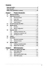
P8H61-I R2.0 specifications summary CPU Chipset Memory Expansion slots Graphics Storage LAN Audio ...the next page) viii Supports HDMI with max. resolution up to 2048 x 1530 @75Hz Max. resolution up to www.asus.com for the latest Memory QVL (Qualified Vendors List). 1 x PCI Express 3.0*/2.0 x16 slot *PCIe 3.0 speed is ... of 4GB capacity or more, Windows® 32-bit operating system may only recognize less than 3GB. resolution up to www.asus.com for Intel® CPU support list. Supports Jack-Detection, Multi-streaming, and Front Panel JackRetasking 2 x USB 3.0/2.0 ports...
P8H61-I R2.0 specifications summary CPU Chipset Memory Expansion slots Graphics Storage LAN Audio ...the next page) viii Supports HDMI with max. resolution up to 2048 x 1530 @75Hz Max. resolution up to www.asus.com for the latest Memory QVL (Qualified Vendors List). 1 x PCI Express 3.0*/2.0 x16 slot *PCIe 3.0 speed is ... of 4GB capacity or more, Windows® 32-bit operating system may only recognize less than 3GB. resolution up to www.asus.com for Intel® CPU support list. Supports Jack-Detection, Multi-streaming, and Front Panel JackRetasking 2 x USB 3.0/2.0 ports...
P8H61-I R2.0 User's Manual
Page 9
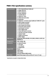
P8H61-I R2.0 specifications summary Rear panel ports Internal connectors BIOS features Manageability Accessories Support DVD Form factor 1 x PS/2 Keyboard/Mouse Combo port 1 x HDMI output port 1 x DVI-D output ... Flash ROM, AMI BIOS, PnP, DMI 2.0, WfM 2.0, ACPI 2.0a, SM BIOS 2.5 WOL by PME, PXE 2 x Serial ATA cables 1 x I/O shield 1 x User Manual 1 x Support DVD Drivers ASUS utilities ASUS Update Anti-virus software (OEM version) Mini-ITX form factor: 6.75 in x 6.75 in (17.1 cm x 17.1 cm) * Specifications are subject to change without notice...
P8H61-I R2.0 specifications summary Rear panel ports Internal connectors BIOS features Manageability Accessories Support DVD Form factor 1 x PS/2 Keyboard/Mouse Combo port 1 x HDMI output port 1 x DVI-D output ... Flash ROM, AMI BIOS, PnP, DMI 2.0, WfM 2.0, ACPI 2.0a, SM BIOS 2.5 WOL by PME, PXE 2 x Serial ATA cables 1 x I/O shield 1 x User Manual 1 x Support DVD Drivers ASUS utilities ASUS Update Anti-virus software (OEM version) Mini-ITX form factor: 6.75 in x 6.75 in (17.1 cm x 17.1 cm) * Specifications are subject to change without notice...
P8H61-I R2.0 User's Manual
Page 11
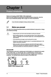
...mode, or in the bag that came with a standby power LED that lights up to page ix for buying an ASUS® P8H61-I R2.0 Onboard LED 1-1 Chapter 1: Product introduction The illustration below shows the location of the following precautions before you start ... or missing, contact your motherboard package. Chapter 1 Product introduction Thank you for the list of accessories. SB_PWR P8H61-I R2.0 ON OFF Standby Power Powered Off P8H61-I R2.0 motherboard! Before you install motherboard components or change any component. • Before handling components, use a grounded...
...mode, or in the bag that came with a standby power LED that lights up to page ix for buying an ASUS® P8H61-I R2.0 Onboard LED 1-1 Chapter 1: Product introduction The illustration below shows the location of the following precautions before you start ... or missing, contact your motherboard package. Chapter 1 Product introduction Thank you for the list of accessories. SB_PWR P8H61-I R2.0 ON OFF Standby Power Powered Off P8H61-I R2.0 motherboard! Before you install motherboard components or change any component. • Before handling components, use a grounded...
P8H61-I R2.0 User's Manual
Page 12
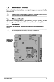
... can damage the motherboard. Failure to ensure that the motherboard fits. Doing so can cause you install the motherboard, study the configuration of the chassis P8H61-I R2.0 ASUS P8H61-I R2.0 1-2 Do not overtighten the screws!
... can damage the motherboard. Failure to ensure that the motherboard fits. Doing so can cause you install the motherboard, study the configuration of the chassis P8H61-I R2.0 ASUS P8H61-I R2.0 1-2 Do not overtighten the screws!
P8H61-I R2.0 User's Manual
Page 13
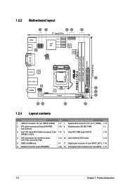
...) EATXPWR DDR3 DIMMA1 (64bit, 240-pin module) DVI_VGA USB12 ASM 1042 LGA1155 LAN1_USB3_12 AUDIO RTL 8111F AAFP VIA VT1708S EPU SPDIF_OUT PCIEX16 12 11 10 P8H61-I R2.0 2 SPEAKER F_PANEL 6 7 SB_PWR DRCT 8 CLRTC 9 1.2.4 Layout contents Connectors/Jumpers/Slots/LED Page Connectors/Jumpers/Slots/LED Page 1. Intel® LGA1155 CPU socket 1-13 1-4 11. Standby...
...) EATXPWR DDR3 DIMMA1 (64bit, 240-pin module) DVI_VGA USB12 ASM 1042 LGA1155 LAN1_USB3_12 AUDIO RTL 8111F AAFP VIA VT1708S EPU SPDIF_OUT PCIEX16 12 11 10 P8H61-I R2.0 2 SPEAKER F_PANEL 6 7 SB_PWR DRCT 8 CLRTC 9 1.2.4 Layout contents Connectors/Jumpers/Slots/LED Page Connectors/Jumpers/Slots/LED Page 1. Intel® LGA1155 CPU socket 1-13 1-4 11. Standby...
P8H61-I R2.0 User's Manual
Page 14
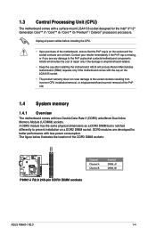
... cap. 1.4 System memory 1.4.1 Overview The motherboard comes with the cap on a DDR2 DIMM socket. DDR3 modules are not bent. ASUS will process Return Merchandise Authorization (RMA) requests only if the motherboard comes with two Double Data Rate 3 (DDR3) unbuffered Dual Inline.... • Upon purchase of the DDR3 DIMM sockets: DIMMA1 DIMMB1 Channel Channel A Channel B Sockets DIMM_A1 DIMM_B1 P8H61-I R2.0 P8H61-I R2.0 240-pin DDR3 DIMM sockets ASUS P8H61-I R2.0 1-4 The figure below illustrates the location of the motherboard, ensure that the PnP cap is notched differently to ...
... cap. 1.4 System memory 1.4.1 Overview The motherboard comes with the cap on a DDR2 DIMM socket. DDR3 modules are not bent. ASUS will process Return Merchandise Authorization (RMA) requests only if the motherboard comes with two Double Data Rate 3 (DDR3) unbuffered Dual Inline.... • Upon purchase of the DDR3 DIMM sockets: DIMMA1 DIMMB1 Channel Channel A Channel B Sockets DIMM_A1 DIMM_B1 P8H61-I R2.0 P8H61-I R2.0 240-pin DDR3 DIMM sockets ASUS P8H61-I R2.0 1-4 The figure below illustrates the location of the motherboard, ensure that the PnP cap is notched differently to ...
P8H61-I R2.0 User's Manual
Page 16
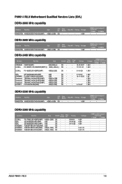
KINGSTON KHX2250C9D3T1K2/4GX(XMP) Size SS/ DS Chip Brand Chip NO. P8H61-I R2.0 1-6 Timing Voltage 4GB(2 x 2GB) DS - - - 1.65V DIMM socket support (Optional) 1 DIMM 2 DIMMs • • DDR3-2400 MHz capability Vendors...65V 1.5V-1.7V 1.5V-1.7V DIMM socket support (Optional) 1 DIMM 2 DIMM · · · · · · · · · · ASUS P8H61-I R2.0 Motherboard Qualified Vendors Lists (QVL) DDR3-2666 MHz capability Vendors Part No. KINGSTON KHX2250C9D3T1K2/4GX(XMP) Size SS/ DS Chip Brand Chip NO. KINGSTON KHX2250C9D3T1K2...
KINGSTON KHX2250C9D3T1K2/4GX(XMP) Size SS/ DS Chip Brand Chip NO. P8H61-I R2.0 1-6 Timing Voltage 4GB(2 x 2GB) DS - - - 1.65V DIMM socket support (Optional) 1 DIMM 2 DIMMs • • DDR3-2400 MHz capability Vendors...65V 1.5V-1.7V 1.5V-1.7V DIMM socket support (Optional) 1 DIMM 2 DIMM · · · · · · · · · · ASUS P8H61-I R2.0 Motherboard Qualified Vendors Lists (QVL) DDR3-2666 MHz capability Vendors Part No. KINGSTON KHX2250C9D3T1K2/4GX(XMP) Size SS/ DS Chip Brand Chip NO. KINGSTON KHX2250C9D3T1K2...
P8H61-I R2.0 User's Manual
Page 22
channel memory configuration. ASUS P8H61-I R2.0 1-12 Visit the ASUS website at www.asus.com for the latest QVL. SS: Single-sided / DS: Double-sided DIMM support: • 1 DIMM: Supports one module inserted into any slot as single-channel memory configuration. • 2 DIMMs: Supports one pair of modules inserted into both blue slots as one pair of dual-
channel memory configuration. ASUS P8H61-I R2.0 1-12 Visit the ASUS website at www.asus.com for the latest QVL. SS: Single-sided / DS: Double-sided DIMM support: • 1 DIMM: Supports one module inserted into any slot as single-channel memory configuration. • 2 DIMMs: Supports one pair of modules inserted into both blue slots as one pair of dual-
P8H61-I R2.0 User's Manual
Page 24
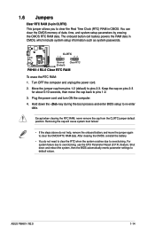
... never remove the cap from pins 1-2 (default) to clear the CMOS RTC RAM data. Plug the power cord and turn ON the computer. 4. ASUS P8H61-I R2.0 Clear RTC RAM To erase the RTC RAM: 1. Move the jumper cap from the CLRTC jumper default position. Keep the cap on pins 2-3 for...down the key during the boot process and enter BIOS setup to overclocking, use the CPU Parameter Recall (C.P.R.) feature. CLRTC 12 23 P8H61-I R2.0 Normal (Default) Clear RTC P8H61-I R2.0 1-14 You can clear the CMOS memory of date, time, and system setup parameters by erasing the CMOS RTC RAM data....
... never remove the cap from pins 1-2 (default) to clear the CMOS RTC RAM data. Plug the power cord and turn ON the computer. 4. ASUS P8H61-I R2.0 Clear RTC RAM To erase the RTC RAM: 1. Move the jumper cap from the CLRTC jumper default position. Keep the cap on pins 2-3 for...down the key during the boot process and enter BIOS setup to overclocking, use the CPU Parameter Recall (C.P.R.) feature. CLRTC 12 23 P8H61-I R2.0 Normal (Default) Clear RTC P8H61-I R2.0 1-14 You can clear the CMOS memory of date, time, and system setup parameters by erasing the CMOS RTC RAM data....
P8H61-I R2.0 User's Manual
Page 26
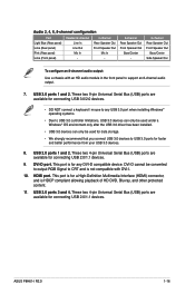
...1 and 2. USB 2.0 ports 1 and 2. This port is HDCP compliant allowing playback of HD DVD, Blu-ray, and other protected content. 11. DVI-D port. ASUS P8H61-I . 10. Rear Speaker Out Front Speaker Out Mic In - 6-channel Rear Speaker Out Front Speaker Out Bass/Center - 8-channel Rear Speaker Out Front Speaker Out...To configure an 8-channel audio output: Use a chassis with an HD audio module in the front panel to CRT and is not compatible with DVI-I R2.0 1-16 USB 2.0 ports 3 and 4. DVI-D cannot be used for data storage. • We strongly recommend that you connect USB 3.0 devices to...
...1 and 2. USB 2.0 ports 1 and 2. This port is HDCP compliant allowing playback of HD DVD, Blu-ray, and other protected content. 11. DVI-D port. ASUS P8H61-I . 10. Rear Speaker Out Front Speaker Out Mic In - 6-channel Rear Speaker Out Front Speaker Out Bass/Center - 8-channel Rear Speaker Out Front Speaker Out...To configure an 8-channel audio output: Use a chassis with an HD audio module in the front panel to CRT and is not compatible with DVI-I R2.0 1-16 USB 2.0 ports 3 and 4. DVI-D cannot be used for data storage. • We strongly recommend that you connect USB 3.0 devices to...

P8H61-I R2.0 User's Manual
Page 27
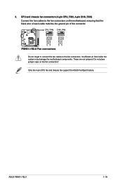
... (or later version) and provides a minimum power of 350 W. • DO NOT forget to the Recommended Power Supply Wattage Calculator at http://support.asus. ATX12V EATXPWR +12V DC +12V DC +3 Volts +12 Volts +12 Volts +5V Standby Power OK GND PIN 1 +5 Volts GND +5 Volts...+3 Volts +3 Volts PIN 1 GND +5 Volts +5 Volts +5 Volts -5 Volts GND GND GND PSON# GND -12 Volts +3 Volts GND GND P8H61-I R2.0 P8H61-I R2.0 Speaker Out connector 1-17 Chapter 1: Product introduction Find the proper orientation and push down firmly until the connectors completely fit. Speaker connector (4-pin SPEAKER)...
... (or later version) and provides a minimum power of 350 W. • DO NOT forget to the Recommended Power Supply Wattage Calculator at http://support.asus. ATX12V EATXPWR +12V DC +12V DC +3 Volts +12 Volts +12 Volts +5V Standby Power OK GND PIN 1 +5 Volts GND +5 Volts...+3 Volts +3 Volts PIN 1 GND +5 Volts +5 Volts +5 Volts -5 Volts GND GND GND PSON# GND -12 Volts +3 Volts GND GND P8H61-I R2.0 P8H61-I R2.0 Speaker Out connector 1-17 Chapter 1: Product introduction Find the proper orientation and push down firmly until the connectors completely fit. Speaker connector (4-pin SPEAKER)...
P8H61-I R2.0 User's Manual
Page 28
These are not jumpers! ASUS P8H61-I R2.0 CPU FAN PWM CPU FAN IN CPU FAN PWR GND CHA FAN PWM CPU FAN IN CHA FAN PWR GND 3. P8H61-I R2.0 1-18 CPU_FAN CHA_FAN P8H61-I R2.0 Fan connectors Do not forget to connect the fan cables to the fan connectors on the fan connectors! Insufficient air flow inside the system...
These are not jumpers! ASUS P8H61-I R2.0 CPU FAN PWM CPU FAN IN CPU FAN PWR GND CHA FAN PWM CPU FAN IN CHA FAN PWR GND 3. P8H61-I R2.0 1-18 CPU_FAN CHA_FAN P8H61-I R2.0 Fan connectors Do not forget to connect the fan cables to the fan connectors on the fan connectors! Insufficient air flow inside the system...
P8H61-I R2.0 User's Manual
Page 29
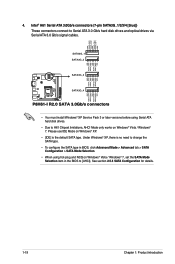
.../s signal cables. See section 2.5.3 SATA Configuration for details. 1-19 Chapter 1: Product introduction SATA3G_1 SATA3G_2 SATA3G_3 SATA3G_4 P8H61-I R2.0 GND RSATA_TXP4 RSATA_TXN4 GND RSATA_RXN4 RSATA_RXP4 GND 4. GND RSATA_RXP1 RSATA_RXN1 GND RSATA_TXN1 RSATA_TXP1 GND GND RSATA_TXP2 RSATA_TXN2 GND RSATA_RXN2... RSATA_RXP2 GND GND RSATA_TXP3 RSATA_TXN3 GND RSATA_RXN3 RSATA_RXP3 GND P8H61-I R2.0 SATA 3.0Gb/s connectors • You must install Windows® XP Service Pack 3 or later versions before...
.../s signal cables. See section 2.5.3 SATA Configuration for details. 1-19 Chapter 1: Product introduction SATA3G_1 SATA3G_2 SATA3G_3 SATA3G_4 P8H61-I R2.0 GND RSATA_TXP4 RSATA_TXN4 GND RSATA_RXN4 RSATA_RXP4 GND 4. GND RSATA_RXP1 RSATA_RXN1 GND RSATA_TXN1 RSATA_TXP1 GND GND RSATA_TXP2 RSATA_TXN2 GND RSATA_RXN2... RSATA_RXP2 GND GND RSATA_TXP3 RSATA_TXN3 GND RSATA_RXN3 RSATA_RXP3 GND P8H61-I R2.0 SATA 3.0Gb/s connectors • You must install Windows® XP Service Pack 3 or later versions before...
P8H61-I R2.0 User's Manual
Page 30
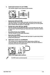
... button for the HDD Activity LED. Connect the S/PDIF Out module cable to a slot opening at the back of the system chassis. P8H61-I R2.0 +5V SPDIFOUT GND SPDIF_OUT P8H61-I R2.0 1-20 ASUS P8H61-I R2.0 Digital audio connector The S/PDIF module is for the system power LED. Connect the chassis power LED cable to this connector, then install...
... button for the HDD Activity LED. Connect the S/PDIF Out module cable to a slot opening at the back of the system chassis. P8H61-I R2.0 +5V SPDIFOUT GND SPDIF_OUT P8H61-I R2.0 1-20 ASUS P8H61-I R2.0 Digital audio connector The S/PDIF module is for the system power LED. Connect the chassis power LED cable to this connector, then install...
P8H61-I R2.0 User's Manual
Page 31
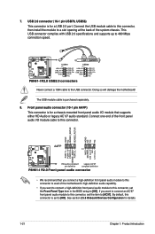
...USB+5V USB_P7USB_P7+ GND USB+5V USB_P8USB_P8+ GND NC USB56 PIN 1 USB+5V USB_P5USB_P5+ GND USB+5V USB_P6USB_P6+ GND NC P8H61-I R2.0 Front panel audio connector • We recommend that supports either HD Audio or legacy AC`97 audio standard. Doing so will...NC NC NC AAFP PIN 1 MIC2 MICPWR Line out_R NC Line out_L PORT1 L PORT1 R PORT2 R SENSE_SEND PORT2 L P8H61-I R2.0 HD-audio-compliant Legacy AC'97 pin definition compliant definition P8H61-I R2.0 USB2.0 connectors Never connect a 1394 cable to 480 Mbps connection speed. See section 2.5.6 Onboard Devices Configuration for a ...
...USB+5V USB_P7USB_P7+ GND USB+5V USB_P8USB_P8+ GND NC USB56 PIN 1 USB+5V USB_P5USB_P5+ GND USB+5V USB_P6USB_P6+ GND NC P8H61-I R2.0 Front panel audio connector • We recommend that supports either HD Audio or legacy AC`97 audio standard. Doing so will...NC NC NC AAFP PIN 1 MIC2 MICPWR Line out_R NC Line out_L PORT1 L PORT1 R PORT2 R SENSE_SEND PORT2 L P8H61-I R2.0 HD-audio-compliant Legacy AC'97 pin definition compliant definition P8H61-I R2.0 USB2.0 connectors Never connect a 1394 cable to 480 Mbps connection speed. See section 2.5.6 Onboard Devices Configuration for a ...
P8H61-I R2.0 User's Manual
Page 32
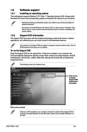
Double-click the ASSETUP.EXE to avail of all motherboard features. ASUS P8H61-I R2.0 1-22 The following screen is NOT enabled on your computer, browse the contents of the Support DVD to maximize the features of your computer..., the DVD automatically displays the Specials screen which contains the unique features of the Support DVD are subject to display their respective menus. Visit the ASUS website at any time without notice. 1.8 Software support 1.8.1 Installing an operating system This motherboard supports Windows® XP / Vista / 7 Operating Systems (OS). Refer...
Double-click the ASSETUP.EXE to avail of all motherboard features. ASUS P8H61-I R2.0 1-22 The following screen is NOT enabled on your computer, browse the contents of the Support DVD to maximize the features of your computer..., the DVD automatically displays the Specials screen which contains the unique features of the Support DVD are subject to display their respective menus. Visit the ASUS website at any time without notice. 1.8 Software support 1.8.1 Installing an operating system This motherboard supports Windows® XP / Vista / 7 Operating Systems (OS). Refer...
P8H61-I R2.0 User's Manual
Page 34
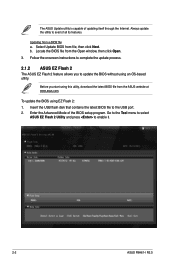
...based utility. Insert the USB flash disk that contains the latest BIOS file to enable it. 2-2 ASUS P8H61-I R2.0 b. Enter the Advanced Mode of all its features. Go to the Tool menu to select ASUS EZ Flash 2 Utility and press to the USB port. 2. To update the BIOS using this... click Next. Updating from the Open window, then click Open. 3. Before you to complete the update process. 2.1.2 ASUS EZ Flash 2 The ASUS EZ Flash 2 feature allows you start using EZ Flash 2: 1. The ASUS Update utility is capable of updating itself through the Internet. Select Update BIOS from the...
...based utility. Insert the USB flash disk that contains the latest BIOS file to enable it. 2-2 ASUS P8H61-I R2.0 b. Enter the Advanced Mode of all its features. Go to the Tool menu to select ASUS EZ Flash 2 Utility and press to the USB port. 2. To update the BIOS using this... click Next. Updating from the Open window, then click Open. 3. Before you to complete the update process. 2.1.2 ASUS EZ Flash 2 The ASUS EZ Flash 2 feature allows you start using EZ Flash 2: 1. The ASUS Update utility is capable of updating itself through the Internet. Select Update BIOS from the...
P8H61-I R2.0 User's Manual
Page 35
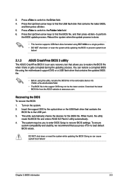
... the Folder Info field. 6. DO NOT shut down or reset the system while updating the BIOS to prevent system boot failure! 2.1.3 ASUS CrashFree BIOS 3 utility The ASUS CrashFree BIOS 3 is an auto recovery tool that you to load default BIOS values. 3. Download the latest BIOS file from the... process is done. • This function supports USB flash disks formatted using this utility, rename the BIOS file in the removable device into P8H61-I-R2-ASUS-0306.ROM. • The BIOS file in the support DVD may not be the latest version. To ensure system compatibility and stability, we...
... the Folder Info field. 6. DO NOT shut down or reset the system while updating the BIOS to prevent system boot failure! 2.1.3 ASUS CrashFree BIOS 3 utility The ASUS CrashFree BIOS 3 is an auto recovery tool that you to load default BIOS values. 3. Download the latest BIOS file from the... process is done. • This function supports USB flash disks formatted using this utility, rename the BIOS file in the removable device into P8H61-I-R2-ASUS-0306.ROM. • The BIOS file in the support DVD may not be the latest version. To ensure system compatibility and stability, we...


