User Manual
Page 3
Contents Notices...v Safety information vi About this guide vi P7H55-M LE Series specifications summary viii Chapter 1: Product introduction 1.1 Before you proceed 1-1 1.2 Motherboard overview 1-2 1.2.1 Motherboard layout 1-2 1.2.2 Layout contents 1-2 1.3 Central... 1-9 1.7.2 Internal connectors 1-10 1.8 Software support 1-17 1.8.1 Installing an operating system 1-17 1.8.2 Support DVD information 1-17 Chapter 2: BIOS information 2.1 Managing and updating your BIOS 2-1 2.1.1 ASUS Update 2-1 2.1.2 ASUS EZ Flash 2 2-2 2.1.3 ASUS BIOS Updater 2-3 2.1.4 ASUS CrashFree BIOS 3 2-6 iii
Contents Notices...v Safety information vi About this guide vi P7H55-M LE Series specifications summary viii Chapter 1: Product introduction 1.1 Before you proceed 1-1 1.2 Motherboard overview 1-2 1.2.1 Motherboard layout 1-2 1.2.2 Layout contents 1-2 1.3 Central... 1-9 1.7.2 Internal connectors 1-10 1.8 Software support 1-17 1.8.1 Installing an operating system 1-17 1.8.2 Support DVD information 1-17 Chapter 2: BIOS information 2.1 Managing and updating your BIOS 2-1 2.1.1 ASUS Update 2-1 2.1.2 ASUS EZ Flash 2 2-2 2.1.3 ASUS BIOS Updater 2-3 2.1.4 ASUS CrashFree BIOS 3 2-6 iii
User Manual
Page 4
Contents 2.2 BIOS setup program 2-7 2.3 Main menu 2-8 2.3.1 System Time [xx:xx:xx 2-8 2.3.2 System Date [Day xx/xx/xxxx 2-8 2.3.3 Legacy Diskette A [1.44M, 3.5 in 2-8 2.3.4 Language [English 2-8 2.3.5 SATA 1-6 ...2.6 Boot menu 2-17 2.6.1 Boot Device Priority 2-17 2.6.2 Boot Settings Configuration 2-17 2.6.3 Security 2-18 2.7 Tools menu 2-19 2.8 Exit menu 2-20 P7P55/P7H57/P7H55 series motherboardsinstallation notices.......... 2-21 Intel® LGA1156 processor and chipset combination instruction.. 2-21 Memory configuration 2-21 Configurations for the PCI Express x16 slots 2-21 iv
Contents 2.2 BIOS setup program 2-7 2.3 Main menu 2-8 2.3.1 System Time [xx:xx:xx 2-8 2.3.2 System Date [Day xx/xx/xxxx 2-8 2.3.3 Legacy Diskette A [1.44M, 3.5 in 2-8 2.3.4 Language [English 2-8 2.3.5 SATA 1-6 ...2.6 Boot menu 2-17 2.6.1 Boot Device Priority 2-17 2.6.2 Boot Settings Configuration 2-17 2.6.3 Security 2-18 2.7 Tools menu 2-19 2.8 Exit menu 2-20 P7P55/P7H57/P7H55 series motherboardsinstallation notices.......... 2-21 Intel® LGA1156 processor and chipset combination instruction.. 2-21 Memory configuration 2-21 Configurations for the PCI Express x16 slots 2-21 iv
User Manual
Page 6
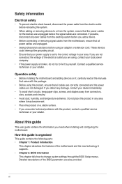
...an adapter or extension cord. Do not place the product in your power supply is set to fix it supports. • Chapter 2: BIOS information This chapter tells how to or from the system, ensure that came with the product, contact a qualified service technician or your retailer....If the power supply is organized This guide contains the following parts: • Chapter 1: Product introduction This chapter describes the features of the BIOS parameters are not damaged. About this guide is broken, do not try to the correct voltage in any damage, contact your retailer. Operation safety...
...an adapter or extension cord. Do not place the product in your power supply is set to fix it supports. • Chapter 2: BIOS information This chapter tells how to or from the system, ensure that came with the product, contact a qualified service technician or your retailer....If the power supply is organized This guide contains the following parts: • Chapter 1: Product introduction This chapter describes the features of the BIOS parameters are not damaged. About this guide is broken, do not try to the correct voltage in any damage, contact your retailer. Operation safety...
User Manual
Page 8
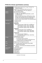
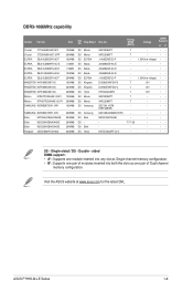
... 3GB. DVI-D with Max. Supports Multi-streaming 12 x USB 2.0/1.1 ports (6 ports at the mid-board, 6 ports at the back panel) ASUS CrashFree BIOS 3 Anti-Surge protection ASUS EZ Flash 2 ASUS Q-Fan 2 ASUS AI NET 2 ASUS MyLogo 2 (continued on the next page) viii P7H55-M LE Series specifications summary CPU Chipset Memory Expansion slots VGA output Storage LAN Audio USB...
... 3GB. DVI-D with Max. Supports Multi-streaming 12 x USB 2.0/1.1 ports (6 ports at the mid-board, 6 ports at the back panel) ASUS CrashFree BIOS 3 Anti-Surge protection ASUS EZ Flash 2 ASUS Q-Fan 2 ASUS AI NET 2 ASUS MyLogo 2 (continued on the next page) viii P7H55-M LE Series specifications summary CPU Chipset Memory Expansion slots VGA output Storage LAN Audio USB...
User Manual
Page 9
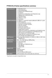
... connector (for P7H55-M LE only) 1 x Floppy disk drive connector (for P7H55-M LE only) 1 x LPT connector (for P7H55-M LE only) 64 Mb Flash ROM, AMI BIOS, PnP, DMI v2.0, WfM 2.0, ACPI v2.0a, SM BIOS v2.5 WOL, PXE, PME Wake up, WOR by Ring 2 x Serial ATA cables 1 x I/O shield 1 x IDE cable (for P7H55-M LE only) 1 x User Manual 1 x Support DVD Drivers ASUS PC Probe...
... connector (for P7H55-M LE only) 1 x Floppy disk drive connector (for P7H55-M LE only) 1 x LPT connector (for P7H55-M LE only) 64 Mb Flash ROM, AMI BIOS, PnP, DMI v2.0, WfM 2.0, ACPI v2.0a, SM BIOS v2.5 WOL, PXE, PME Wake up, WOR by Ring 2 x Serial ATA cables 1 x I/O shield 1 x IDE cable (for P7H55-M LE only) 1 x User Manual 1 x Support DVD Drivers ASUS PC Probe...
User Manual
Page 11
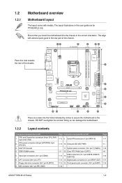
...pin USB78, USB910, USB1112) 1-15 14. Front panel audio connector (10-1 pin AAFP) 1-16 Page 1-11 1-1 1-12 1-8 1-10 1-11 1-14 ASUS P7H55-M LE Series 1-2 The edge with models. Doing so can damage the motherboard. 1.2.2 Layout contents Connectors/Jumpers/Slots/LED 1. Onboard LED (SB_PWR) 11. Ensure that... CHA_FAN AUDIO RTL 8112L VIA VT1708S AAFP CPU_FAN ICS 954 A4 Lithium Cell CMOS Power PCIEX16 P7H55-M LE PCI1 PCI2 PCIEX4_1 SPDIF_OUT USB1112 USB910 Intel® H55 64Mb BIOS SATA1 SATA2 SATA3 SATA4 USB78 CLRTC SATA5 SATA6 SB_PWR F_PANEL 2 8 9 10 15 14 ...
...pin USB78, USB910, USB1112) 1-15 14. Front panel audio connector (10-1 pin AAFP) 1-16 Page 1-11 1-1 1-12 1-8 1-10 1-11 1-14 ASUS P7H55-M LE Series 1-2 The edge with models. Doing so can damage the motherboard. 1.2.2 Layout contents Connectors/Jumpers/Slots/LED 1. Onboard LED (SB_PWR) 11. Ensure that... CHA_FAN AUDIO RTL 8112L VIA VT1708S AAFP CPU_FAN ICS 954 A4 Lithium Cell CMOS Power PCIEX16 P7H55-M LE PCI1 PCI2 PCIEX4_1 SPDIF_OUT USB1112 USB910 Intel® H55 64Mb BIOS SATA1 SATA2 SATA3 SATA4 USB78 CLRTC SATA5 SATA6 SB_PWR F_PANEL 2 8 9 10 15 14 ...
User Manual
Page 13
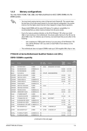
...the motherboard. • This motherboard does not support DIMMs made up of 256 megabits (Mb) chips or less. P7H55-M LE Series Motherboard Qualified Vendors List (QVL) DDR3-1333MHz capability Vendor A-Data A-Data A-Data Apacer CORSAIR CORSAIR CORSAIR CORSAIR ... the memory address limitation on the 32-bit Windows® OS, when you want to install 4GB or more memory on the next page) ASUS P7H55-M LE Series 1-4 Timing DIMM (BIOS) 8-8-8-24 8-8-8-24 9-9-9-24 9-9-9-24 9-9-9-24 9-9-9-24 9 9-9-9-24 9-9-9-24 9 6-6-6-20 9 6-6-6-20 6-6-6-20 7-7-7-24 - - 7-7-7-18 9-9-9-24 Voltage DIMM...
...the motherboard. • This motherboard does not support DIMMs made up of 256 megabits (Mb) chips or less. P7H55-M LE Series Motherboard Qualified Vendors List (QVL) DDR3-1333MHz capability Vendor A-Data A-Data A-Data Apacer CORSAIR CORSAIR CORSAIR CORSAIR ... the memory address limitation on the 32-bit Windows® OS, when you want to install 4GB or more memory on the next page) ASUS P7H55-M LE Series 1-4 Timing DIMM (BIOS) 8-8-8-24 8-8-8-24 9-9-9-24 9-9-9-24 9-9-9-24 9-9-9-24 9 9-9-9-24 9-9-9-24 9 6-6-6-20 9 6-6-6-20 6-6-6-20 7-7-7-24 - - 7-7-7-18 9-9-9-24 Voltage DIMM...

User Manual
Page 14
... Samsung K4B1G0846D-HCH9 Samsung SEC 846 HCH9 K4B1G08460 Samsung SEC 913 HCH9 K4B1G0846E Samsung K4B1G0846D-HCH9 Samsung SEC 913 HCH9 K4B1G0846E Micron 9GF27D9KPT Timing DIMM (BIOS) - Voltage - F3-10600CL9D-2GBNQ 1024MB DS F3-10666CL8D4GBECO(XMP) 4096MB(Kit of 2 ) DS F3-10666CL8D-4GBHK(XMP) 4096MB(Kit of 2 ) DS F3-10666CL7T-6GBPK(XMP...
... Samsung K4B1G0846D-HCH9 Samsung SEC 846 HCH9 K4B1G08460 Samsung SEC 913 HCH9 K4B1G0846E Samsung K4B1G0846D-HCH9 Samsung SEC 913 HCH9 K4B1G0846E Micron 9GF27D9KPT Timing DIMM (BIOS) - Voltage - F3-10600CL9D-2GBNQ 1024MB DS F3-10666CL8D4GBECO(XMP) 4096MB(Kit of 2 ) DS F3-10666CL8D-4GBHK(XMP) 4096MB(Kit of 2 ) DS F3-10666CL7T-6GBPK(XMP...
User Manual
Page 15
Single-sided / DS - ASUS P7H55-M LE Series 1-6 DDR3-1066MHz capability Vendor Part No. Visit the ASUS website at www.asus.com for the latest QVL. Voltage DIMM Support A* C* - •• - •• 1.35V(low voltage) • • - ...-AC-E J5308BASE-AC-E J1108EDSE-DJ-F D1288JEKAPGA7U D1288JEKAPGA7U H5TQ2G83AFR 9GF22D9KPT 9HF22D9KPT SEC 901 HCF8 K4B1G0846E 846 K4B2G0846B-HCF8 N2CB1G80CN-BE H5TQ1G83AFP G7C Timing DIMM (BIOS) 7 7 7 7 7 7 7 - 7-7-7-20 - Crucial CT12864BA1067.8FF Crucial CT25664BA1067.16FF ELPIDA EBJ10UE8EDF0-AE-F ELPIDA EBJ51UD8BAFA-AC-E ELPIDA...
Single-sided / DS - ASUS P7H55-M LE Series 1-6 DDR3-1066MHz capability Vendor Part No. Visit the ASUS website at www.asus.com for the latest QVL. Voltage DIMM Support A* C* - •• - •• 1.35V(low voltage) • • - ...-AC-E J5308BASE-AC-E J1108EDSE-DJ-F D1288JEKAPGA7U D1288JEKAPGA7U H5TQ2G83AFR 9GF22D9KPT 9HF22D9KPT SEC 901 HCF8 K4B1G0846E 846 K4B2G0846B-HCF8 N2CB1G80CN-BE H5TQ1G83AFP G7C Timing DIMM (BIOS) 7 7 7 7 7 7 7 - 7-7-7-20 - Crucial CT12864BA1067.8FF Crucial CT25664BA1067.16FF ELPIDA EBJ10UE8EDF0-AE-F ELPIDA EBJ51UD8BAFA-AC-E ELPIDA...
User Manual
Page 16
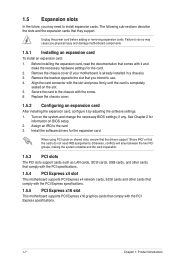
.... 1.5.5 PCI Express x16 slot This motherboard supports PCI Express x16 graphics cards that they support. See Chapter 2 for the card. 2. When using PCI cards on BIOS setup. 2. Turn on the slot. 5. Install the software drivers for the expansion card. otherwise, conflicts will arise between the two PCI groups, making the system... and other cards that comply with the screw. 6. Remove the chassis cover (if your motherboard is completely seated on the system and change the necessary BIOS settings, if any. Unplug the power cord before adding or removing expansion cards.
.... 1.5.5 PCI Express x16 slot This motherboard supports PCI Express x16 graphics cards that they support. See Chapter 2 for the card. 2. When using PCI cards on BIOS setup. 2. Turn on the slot. 5. Install the software drivers for the expansion card. otherwise, conflicts will arise between the two PCI groups, making the system... and other cards that comply with the screw. 6. Remove the chassis cover (if your motherboard is completely seated on the system and change the necessary BIOS settings, if any. Unplug the power cord before adding or removing expansion cards.
User Manual
Page 17
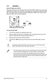
...then reboot the system, the BIOS automatically resets parameter settings to default values. Removing the cap will cause system boot failure! • If the steps above do not need to clear the RTC when the system hangs due to overclocking. ASUS P7H55-M LE Series 1-8 Move the jumper cap... from pins 1-2 (default) to overclocking, use the CPU Parameter Recall (C.P.R.) feature. You can clear the CMOS memory of date, time, and system setup parameters by erasing the CMOS RTC RAM data. P7H55-M LE CLRTC 12 23 Normal...
...then reboot the system, the BIOS automatically resets parameter settings to default values. Removing the cap will cause system boot failure! • If the steps above do not need to clear the RTC when the system hangs due to overclocking. ASUS P7H55-M LE Series 1-8 Move the jumper cap... from pins 1-2 (default) to overclocking, use the CPU Parameter Recall (C.P.R.) feature. You can clear the CMOS memory of date, time, and system setup parameters by erasing the CMOS RTC RAM data. P7H55-M LE CLRTC 12 23 Normal...
User Manual
Page 23
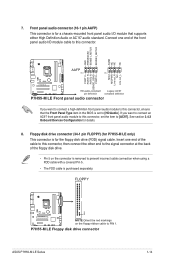
P7H55-M LE Floppy disk drive connector ASUS P7H55-M LE Series 1-14 Front panel audio connector (10-1 pin AAFP) This connector is purchased separately. FLOPPY PIN1 P7H55-M LE NOTE:Orient the red markings on the connector is removed to this connector, ensure that supports either High Definition ...item in the BIOS is for a chassis-mounted front panel audio I /O module cable to this connector, then connect the other end to the signal connector at the back of the cable to [HD Audio]. 7. Floppy disk drive connector (34-1 pin FLOPPY) (for P7H55-M LE only) This connector...
P7H55-M LE Floppy disk drive connector ASUS P7H55-M LE Series 1-14 Front panel audio connector (10-1 pin AAFP) This connector is purchased separately. FLOPPY PIN1 P7H55-M LE NOTE:Orient the red markings on the connector is removed to this connector, ensure that supports either High Definition ...item in the BIOS is for a chassis-mounted front panel audio I /O module cable to this connector, then connect the other end to the signal connector at the back of the cable to [HD Audio]. 7. Floppy disk drive connector (34-1 pin FLOPPY) (for P7H55-M LE only) This connector...

User Manual
Page 27
... support DVD into the optical drive. Updating the BIOS To update the BIOS: 1. Select Update BIOS from the Internet a. b. ASUS P7H55-M LE Series 2-1 Copy the original motherboard BIOS using this utility. Select the ASUS FTP site nearest you to manage, save, and update the motherboard BIOS in Windows® environment. • ASUS Update requires an Internet connection either of the...
... support DVD into the optical drive. Updating the BIOS To update the BIOS: 1. Select Update BIOS from the Internet a. b. ASUS P7H55-M LE Series 2-1 Copy the original motherboard BIOS using this utility. Select the ASUS FTP site nearest you to manage, save, and update the motherboard BIOS in Windows® environment. • ASUS Update requires an Internet connection either of the...
User Manual
Page 28
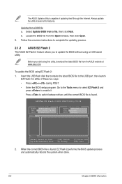
... Update BIOS from the ASUS website at www.asus.com. To update the BIOS using EZ Flash 2: 1. Go to the Tools menu to select EZ Flash 2 and press to the USB port, then launch EZ Flash 2 in either of updating itself through the Internet. ASUSTek EZ Flash 2 BIOS ROM Utility V4.14 Current ROM BOARD: P7H55...
... Update BIOS from the ASUS website at www.asus.com. To update the BIOS using EZ Flash 2: 1. Go to the Tools menu to select EZ Flash 2 and press to the USB port, then launch EZ Flash 2 in either of updating itself through the Internet. ASUSTek EZ Flash 2 BIOS ROM Utility V4.14 Current ROM BOARD: P7H55...
User Manual
Page 29
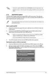
... prevent system boot failure! 2.1.3 ASUS BIOS Updater The ASUS BIOS Updater allows you to the USB port. 2. Insert the support DVD into the optical drive and select the optical drive as shown. The succeeding utility screens are for reference only. When the ASUS Logo appears, press to boot using defaults ASUS P7H55-M LE Series 2-3 Prepare the motherboard support...
... prevent system boot failure! 2.1.3 ASUS BIOS Updater The ASUS BIOS Updater allows you to the USB port. 2. Insert the support DVD into the optical drive and select the optical drive as shown. The succeeding utility screens are for reference only. When the ASUS Logo appears, press to boot using defaults ASUS P7H55-M LE Series 2-3 Prepare the motherboard support...
User Manual
Page 30
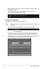
...the USB flash drive is not write-protected and has at least 1024KB free space to Drive D (USB flash drive). The BIOS Updater backup screen appears indicating the BIOS backup process. ASUSTek BIOS Updater for the extension. 2. At the FreeDOS prompt, type d: and press to switch the disk from Drive C (optical...the filename and three alphanumeric characters for DOS V1.00b [09/06/22] Current ROM BOARD: P7H55-M LX VER: 0301 DATE: 07/12/2010 Update ROM BOARD: Unknown VER: Unknown DATE: Unknown PATH: A:\ BIOS backup is done, press any key to FreeDOS (http://www.freedos.org)! Press any key ...
...the USB flash drive is not write-protected and has at least 1024KB free space to Drive D (USB flash drive). The BIOS Updater backup screen appears indicating the BIOS backup process. ASUSTek BIOS Updater for the extension. 2. At the FreeDOS prompt, type d: and press to switch the disk from Drive C (optical...the filename and three alphanumeric characters for DOS V1.00b [09/06/22] Current ROM BOARD: P7H55-M LX VER: 0301 DATE: 07/12/2010 Update ROM BOARD: Unknown VER: Unknown DATE: Unknown PATH: A:\ BIOS backup is done, press any key to FreeDOS (http://www.freedos.org)! Press any key ...
User Manual
Page 31
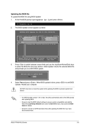
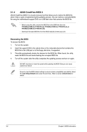
... you sure to connect all SATA hard disk drives after updating BIOS. • Ensure to load the BIOS default settings to confirm BIOS update. Restart your computer. ASUS P7H55-M LE Series 2-5 The BIOS Updater screen appears as below. When BIOS update is done, press to select the BIOS file and press . At the FreeDOS prompt, type bupdater /pc /g and...
... you sure to connect all SATA hard disk drives after updating BIOS. • Ensure to load the BIOS default settings to confirm BIOS update. Restart your computer. ASUS P7H55-M LE Series 2-5 The BIOS Updater screen appears as below. When BIOS update is done, press to select the BIOS file and press . At the FreeDOS prompt, type bupdater /pc /g and...
User Manual
Page 32
... the USB flash drive into P7H55MLE.ROM (for P7H55-M LE), P7H55MLX.ROM (for P7H55-M LX), or PH55MLX2.ROM (for P7H55-M LX2). • Download the latest BIOS file from the ASUS website at www.asus.com. Turn on again. DO NOT shut down or reset the system while updating the BIOS! Refer to ensure system compatibility and stability. Select...
... the USB flash drive into P7H55MLE.ROM (for P7H55-M LE), P7H55MLX.ROM (for P7H55-M LX), or PH55MLX2.ROM (for P7H55-M LX2). • Download the latest BIOS file from the ASUS website at www.asus.com. Turn on again. DO NOT shut down or reset the system while updating the BIOS! Refer to ensure system compatibility and stability. Select...
User Manual
Page 33
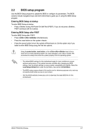
... two options. ASUS P7H55-M LE Series 2-7 Do this motherboard. Using the power button, reset button, or the ++ keys to enter BIOS Setup using the BIOS Setup program. Entering BIOS Setup at startup To enter BIOS Setup at www.asus.com to download the latest BIOS file for most conditions to update the BIOS or configure its routines. 2.2 BIOS setup program Use...
... two options. ASUS P7H55-M LE Series 2-7 Do this motherboard. Using the power button, reset button, or the ++ keys to enter BIOS Setup using the BIOS Setup program. Entering BIOS Setup at startup To enter BIOS Setup at www.asus.com to download the latest BIOS file for most conditions to update the BIOS or configure its routines. 2.2 BIOS setup program Use...

User Manual
Page 34
... Time System Date Legacy Diskette A Language [00:31:48] [Fri 04/10/2009] [1.44M, 3.5 in BIOS. Configuration options: [Disabled] [360K, 5.25 in.] [1.2M , 5.25 in.] [720K , 3.5 in.] [1.44M, 3.5 in.] [2.88M, 3.5 in.] This item appears only on P7H55-M LE. 2.3.4 Language [English] Allows you to choose the display language in .] [English] SATA 1 :[Not Detected] SATA...
... Time System Date Legacy Diskette A Language [00:31:48] [Fri 04/10/2009] [1.44M, 3.5 in BIOS. Configuration options: [Disabled] [360K, 5.25 in.] [1.2M , 5.25 in.] [720K , 3.5 in.] [1.44M, 3.5 in.] [2.88M, 3.5 in.] This item appears only on P7H55-M LE. 2.3.4 Language [English] Allows you to choose the display language in .] [English] SATA 1 :[Not Detected] SATA...


