User Manual
Page 4
Contents 2.8 Connectors 2-25 2.8.1 Rear panel connectors 2-25 2.8.2 Audio I/O connections 2-26 2.8.3 Internal connectors 2-29 2.8.4 ASUS Q-Connector (system panel 2-37 2.9 Starting up for the first time 2-38 2.10 Turning off the computer 2-38 Chapter 3: BIOS setup 3.1 Knowing BIOS 3-1 3.2 Updating BIOS 3-1 3.2.1 ASUS Update utility 3-2 3.2.2 ASUS EZ Flash 2 utility 3-4 3.2.3 ASUS CrashFree BIOS 3 utility 3-5 3.3 BIOS setup program 3-6 3.3.1 BIOS menu screen 3-6 3.3.2 Menu...
Contents 2.8 Connectors 2-25 2.8.1 Rear panel connectors 2-25 2.8.2 Audio I/O connections 2-26 2.8.3 Internal connectors 2-29 2.8.4 ASUS Q-Connector (system panel 2-37 2.9 Starting up for the first time 2-38 2.10 Turning off the computer 2-38 Chapter 3: BIOS setup 3.1 Knowing BIOS 3-1 3.2 Updating BIOS 3-1 3.2.1 ASUS Update utility 3-2 3.2.2 ASUS EZ Flash 2 utility 3-4 3.2.3 ASUS CrashFree BIOS 3 utility 3-5 3.3 BIOS setup program 3-6 3.3.1 BIOS menu screen 3-6 3.3.2 Menu...
User Manual
Page 6
... 4: Software support 4.1 Installing an operating system 4-1 4.2 Support DVD information 4-1 4.2.1 Running the support DVD 4-1 4.2.2 Obtaining the software manuals 4-2 4.3 Software information 4-3 4.3.1 ASUS PC Probe II 4-3 4.3.2 ASUS AI Suite 4-4 4.3.3 ASUS EPU 4-5 4.3.4 ASUS Fan Xpert 4-6 4.3.5 ASUS TurboV 4-7 4.3.6 ASUS Express Gate SSD 4-8 4.3.7 Audio configurations 4-9 4.4 RAID configurations 4-10 4.4.1 RAID definitions 4-10 4.4.2 Installing Serial ATA hard disks 4-11 4.4.3 Setting the RAID item in BIOS...
... 4: Software support 4.1 Installing an operating system 4-1 4.2 Support DVD information 4-1 4.2.1 Running the support DVD 4-1 4.2.2 Obtaining the software manuals 4-2 4.3 Software information 4-3 4.3.1 ASUS PC Probe II 4-3 4.3.2 ASUS AI Suite 4-4 4.3.3 ASUS EPU 4-5 4.3.4 ASUS Fan Xpert 4-6 4.3.5 ASUS TurboV 4-7 4.3.6 ASUS Express Gate SSD 4-8 4.3.7 Audio configurations 4-9 4.4 RAID configurations 4-10 4.4.1 RAID definitions 4-10 4.4.2 Installing Serial ATA hard disks 4-11 4.4.3 Setting the RAID item in BIOS...

User Manual
Page 11
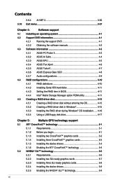
P6X58D Premium specifications summary CPU Chipset System bus Memory Expansion slots Multi-GPU support Storage LAN Audio IEEE 1394 USB LGA1366 socket for Intel® Core™ i7 Processor Extreme Edition / Core™ i7 Processor Supports Intel® Turbo Boost Technology * Refer to www.asus.com for Intel CPU support list Intel® X58 / ICH10R...
P6X58D Premium specifications summary CPU Chipset System bus Memory Expansion slots Multi-GPU support Storage LAN Audio IEEE 1394 USB LGA1366 socket for Intel® Core™ i7 Processor Extreme Edition / Core™ i7 Processor Supports Intel® Turbo Boost Technology * Refer to www.asus.com for Intel CPU support list Intel® X58 / ICH10R...
User Manual
Page 13
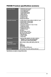
...by PME, WOR by PME, PXE Drivers ASUS Utilities ASUS Update Anti-virus software (OEM version) ATX form factor: 12 in . (30.5 cm x 24.4 cm) *Specifications are subject to change without notice. P6X58D Premium specifications summary Back panel I/O ports Internal ...channel Audio I/O ports 2 x USB connectors support additional 4 USB 2.0/1.1 ports 2 x SATA 6.0 Gb/s connectors (gray) 6 x SATA 3.0 Gb/s connectors (blue) 1 x CPU Fan connector 3 x Chassis Fan connectors (1 x 4-pin, 2 x 3-pin) 1 x Power Fan connector 1 x IEEE1394a connector Front panel audio connector 1 x S/PDIF Out header CD audio in ...
...by PME, WOR by PME, PXE Drivers ASUS Utilities ASUS Update Anti-virus software (OEM version) ATX form factor: 12 in . (30.5 cm x 24.4 cm) *Specifications are subject to change without notice. P6X58D Premium specifications summary Back panel I/O ports Internal ...channel Audio I/O ports 2 x USB connectors support additional 4 USB 2.0/1.1 ports 2 x SATA 6.0 Gb/s connectors (gray) 6 x SATA 3.0 Gb/s connectors (blue) 1 x CPU Fan connector 3 x Chassis Fan connectors (1 x 4-pin, 2 x 3-pin) 1 x Power Fan connector 1 x IEEE1394a connector Front panel audio connector 1 x S/PDIF Out header CD audio in ...
User Manual
Page 18
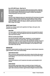
...centric applications like computer fans, air conditioners, and other side of fan speed to 20ºC. ASUS EZ DIY ASUS EZ DIY feature collection provides you may experience a better home-theater audio with easy ways to 20ºC (36ºF) Cooler-Stack Cool 3+ Stack Cool 3+ is... Sensation UltraPC delivers exceptional 5.1 surround experience through the most common PC audio setups-your existing stereo speakers or headphones. making temperatures cooler by the critical components to short the pins! ASUS Onboard Switch With an easy press during overclocking, the exclusive onboard switches...
...centric applications like computer fans, air conditioners, and other side of fan speed to 20ºC. ASUS EZ DIY ASUS EZ DIY feature collection provides you may experience a better home-theater audio with easy ways to 20ºC (36ºF) Cooler-Stack Cool 3+ Stack Cool 3+ is... Sensation UltraPC delivers exceptional 5.1 surround experience through the most common PC audio setups-your existing stereo speakers or headphones. making temperatures cooler by the critical components to short the pins! ASUS Onboard Switch With an easy press during overclocking, the exclusive onboard switches...
User Manual
Page 23
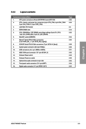
... (7-pin SATA1-6 [blue]) 9. Onboard Power-on switch 14. DDR3 DIMM slots 5. 2.2.2 Layout contents Connectors/Jumpers/Slots 1. Front panel audio connector (10-1 pin AAFP) 16. ATX power connectors (24-pin EATXPWR, 8-pin EATX12V) 2. CPU / DRAM Bus / QPI DRAM...pin SATA_6G_1, 7-pin SATA_6G_2 [gray]) 8. Optical drive audio connector (4-pin CD) 15. Digital audio connector (4-1 pin SPDIF_OUT) Page 2-35 2-33 2-5 2-10 2-22 2-24 2-30 2-29 2-36 2-31 2-32 2-23 2-23 2-32 2-34 2-34 Chapter 2 ASUS P6X58D Premium 2-3 MemOK! Onboard Reset switch 13. USB connectors ...
... (7-pin SATA1-6 [blue]) 9. Onboard Power-on switch 14. DDR3 DIMM slots 5. 2.2.2 Layout contents Connectors/Jumpers/Slots 1. Front panel audio connector (10-1 pin AAFP) 16. ATX power connectors (24-pin EATXPWR, 8-pin EATX12V) 2. CPU / DRAM Bus / QPI DRAM...pin SATA_6G_1, 7-pin SATA_6G_2 [gray]) 8. Optical drive audio connector (4-pin CD) 15. Digital audio connector (4-1 pin SPDIF_OUT) Page 2-35 2-33 2-5 2-10 2-22 2-24 2-30 2-29 2-36 2-31 2-32 2-23 2-23 2-32 2-34 2-34 Chapter 2 ASUS P6X58D Premium 2-3 MemOK! Onboard Reset switch 13. USB connectors ...
User Manual
Page 39
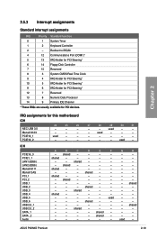
...PCIE1_1 LAN1 (8056) LAN2 (8056) Marvell 6111 Marvell SAS PCI_1 PCI_2 USB_1 USB_2 USB_3 USB_4 USB_5 USB_6 USB 2.0_1 USB 2.0_2 SATA_1 SATA _2 Audio A B C D E F - shared - - - - - - used - - - - - 27 28 29 - - shared - - - - - - - - - - shared - - - - - ASUS P6X58D Premium 2-19 shared - - - - shared - - - - - - - - shared - - - - - - - - - - - - - shared - - - - - - - - - - - shared - - - - - - IRQ assignments for PCI devices. shared - - - - shared - - - - shared - - shared...
...PCIE1_1 LAN1 (8056) LAN2 (8056) Marvell 6111 Marvell SAS PCI_1 PCI_2 USB_1 USB_2 USB_3 USB_4 USB_5 USB_6 USB 2.0_1 USB 2.0_2 SATA_1 SATA _2 Audio A B C D E F - shared - - - - - - used - - - - - 27 28 29 - - shared - - - - - - - - - - shared - - - - - ASUS P6X58D Premium 2-19 shared - - - - shared - - - - - - - - shared - - - - - - - - - - - - - shared - - - - - - - - - - - shared - - - - - - IRQ assignments for PCI devices. shared - - - - shared - - - - shared - - shared...
User Manual
Page 45
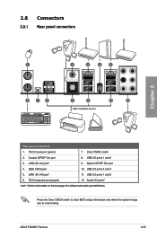
... 3. LAN1 (RJ-45) port* 11. PS/2 keyboard port (purple) 12. IEEE 1394a port 10. Audio I/O ports** *and **: Refer to overclocking. PS/2 mouse port (green) 7. Clear CMOS switch 2. ASUS P6X58D Premium 2-25 LAN2 (RJ-45) port* 9. Press the Clear CMOS switch to clear BIOS setup information only when ...the system hangs due to the tables on the next page for LAN port and audio port definitions. 2.8 Connectors 2.8.1 ...
... 3. LAN1 (RJ-45) port* 11. PS/2 keyboard port (purple) 12. IEEE 1394a port 10. Audio I/O ports** *and **: Refer to overclocking. PS/2 mouse port (green) 7. Clear CMOS switch 2. ASUS P6X58D Premium 2-25 LAN2 (RJ-45) port* 9. Press the Clear CMOS switch to clear BIOS setup information only when ...the system hangs due to the tables on the next page for LAN port and audio port definitions. 2.8 Connectors 2.8.1 ...

User Manual
Page 46
... Center/Subwoofer Rear Speaker Out - 8-channel Line In Front Speaker Out Mic In Center/Subwoofer Rear Speaker Out Side Speaker Out 2.8.2 Audio I/O connections Audio I/O ports Connect to Headphone and Mic 2-26 Chapter 2: Hardware information Chapter 2 * LAN port LED indications Activity Link LED Status...activity Speed LED Status OFF ORANGE GREEN Description 10 Mbps connection 100 Mbps connection 1 Gbps connection ACT/LINK SPEED LED LED LAN port ** Audio 2, 4, 6, or 8-channel configuration Port Light Blue Lime Pink Orange Black Gray Headset 2-channel Line In Line Out Mic In - - ...
... Center/Subwoofer Rear Speaker Out - 8-channel Line In Front Speaker Out Mic In Center/Subwoofer Rear Speaker Out Side Speaker Out 2.8.2 Audio I/O connections Audio I/O ports Connect to Headphone and Mic 2-26 Chapter 2: Hardware information Chapter 2 * LAN port LED indications Activity Link LED Status...activity Speed LED Status OFF ORANGE GREEN Description 10 Mbps connection 100 Mbps connection 1 Gbps connection ACT/LINK SPEED LED LED LAN port ** Audio 2, 4, 6, or 8-channel configuration Port Light Blue Lime Pink Orange Black Gray Headset 2-channel Line In Line Out Mic In - - ...
User Manual
Page 52
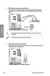
Chapter 2 4. Never connect a USB cable to receive stereo audio input from sound sources such as a CD-ROM, TV tuner, or MPEG card. 2-32 Chapter 2: Hardware information Optical drive audio connector (4-pin CD) These connectors allow you to the IEEE 1394a connector. The IEEE 1394a module cable is for an IEEE 1394a port. Connect the IEEE 1394a module cable to this connector, then install the module to a slot opening at the back of the system chassis. Doing so will damage the motherboard! IEEE 1394a port connector (10-1 pin IE1394_2) This connector is purchased separately. 5.
Chapter 2 4. Never connect a USB cable to receive stereo audio input from sound sources such as a CD-ROM, TV tuner, or MPEG card. 2-32 Chapter 2: Hardware information Optical drive audio connector (4-pin CD) These connectors allow you to the IEEE 1394a connector. The IEEE 1394a module cable is for an IEEE 1394a port. Connect the IEEE 1394a module cable to this connector, then install the module to a slot opening at the back of the system chassis. Doing so will damage the motherboard! IEEE 1394a port connector (10-1 pin IE1394_2) This connector is purchased separately. 5.
User Manual
Page 54
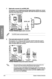
.... 8. Connect the S/PDIF Out module cable to this connector to avail of the system chassis. if you want to connect an AC'97 front panel audio module to this connector, set the item to a slot opening at the back of the motherboard's high-definition... is for an additional Sony/Philips Digital Interface (S/PDIF) port. Connect one end of the front panel audio I /O module that you want to connect a high-definition front panel audio module to this connector, set to [HD Audio]; Chapter 2 The S/PDIF module is set the Front Panel Type item in the BIOS setup to...
.... 8. Connect the S/PDIF Out module cable to this connector to avail of the system chassis. if you want to connect an AC'97 front panel audio module to this connector, set the item to a slot opening at the back of the motherboard's high-definition... is for an additional Sony/Philips Digital Interface (S/PDIF) port. Connect one end of the front panel audio I /O module that you want to connect a high-definition front panel audio module to this connector, set to [HD Audio]; Chapter 2 The S/PDIF module is set the Front Panel Type item in the BIOS setup to...
User Manual
Page 80
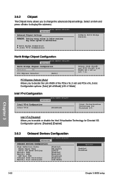
... values in below sections may cause system to malfunction. Configuration options: [Disabled] [Enabled] 3.6.3 Onboard Devices Configuration BIOS SETUP UTILITY Advanced Onboard Devices Configuration High Definition Audio Front Panel Type SPDIF OUT Mode Setting Marvell LAN1 Marvell LAN2 LAN Boot ROM Onboard 1394 Controller Marvell 9123 Controller [Enabled] [HD...
... values in below sections may cause system to malfunction. Configuration options: [Disabled] [Enabled] 3.6.3 Onboard Devices Configuration BIOS SETUP UTILITY Advanced Onboard Devices Configuration High Definition Audio Front Panel Type SPDIF OUT Mode Setting Marvell LAN1 Marvell LAN2 LAN Boot ROM Onboard 1394 Controller Marvell 9123 Controller [Enabled] [HD...

User Manual
Page 81
...] [Enabled] Enables the onboard IEEE 1394a controller. [Disabled] Disables the controller. Chapter 3 ASUS P6X58D Premium 3-23 Front Panel Type [HD Audio] Allows you to set the High Definition Audio item to internally optimize the order of commands.. Marvell 9123 Controller [IDE Mode] Allows you ...] Disables the controller. [IDE Mode] Set to [IDE Mode] when you want the SATA hard disk drives to high definition audio. Marvell LAN1/LAN2 [Enabled] [Enabled] Enables the Marvell LAN1/LAN2 controller. [Disabled] Disables the controller. The following item appears...
...] [Enabled] Enables the onboard IEEE 1394a controller. [Disabled] Disables the controller. Chapter 3 ASUS P6X58D Premium 3-23 Front Panel Type [HD Audio] Allows you to set the High Definition Audio item to internally optimize the order of commands.. Marvell 9123 Controller [IDE Mode] Allows you ...] Disables the controller. [IDE Mode] Set to [IDE Mode] when you want the SATA hard disk drives to high definition audio. Marvell LAN1/LAN2 [Enabled] [Enabled] Enables the Marvell LAN1/LAN2 controller. [Disabled] Disables the controller. The following item appears...
User Manual
Page 84
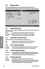
.... [No] The system will not add additional tables as per ACPI 2.0 specifications. Chapter 3 3-26 Chapter 3: BIOS setup When set to [Enabled], power for WOL, WO_USB, audio and onboard LEDs will be used for System Suspend. ←→ Select Screen ↑↓ Select Item Enter Go to Sub Screen F1 General Help...
.... [No] The system will not add additional tables as per ACPI 2.0 specifications. Chapter 3 3-26 Chapter 3: BIOS setup When set to [Enabled], power for WOL, WO_USB, audio and onboard LEDs will be used for System Suspend. ←→ Select Screen ↑↓ Select Item Enter Go to Sub Screen F1 General Help...
User Manual
Page 105
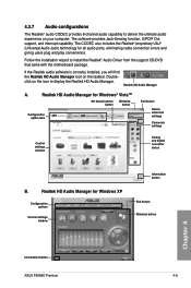
... for Windows XP Configuration options Control settings window Information button Exit button Minimize button Chapter 4 Information button ASUS P6X58D Premium 4-9 Follow the installation wizard to deliver the ultimate audio experience on your computer. Doubleclick on the taskbar. Realtek HD Audio Manager A. The software provides Jack-Sensing function, S/PDIF Out support, and interrupt capability. Realtek HD...
... for Windows XP Configuration options Control settings window Information button Exit button Minimize button Chapter 4 Information button ASUS P6X58D Premium 4-9 Follow the installation wizard to deliver the ultimate audio experience on your computer. Doubleclick on the taskbar. Realtek HD Audio Manager A. The software provides Jack-Sensing function, S/PDIF Out support, and interrupt capability. Realtek HD...
User Manual
Page 109
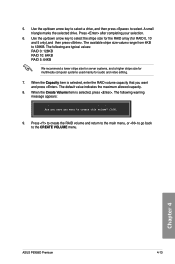
... selection. 6. When the Capacity item is selected, press . The default value indicates the maximum allowed capacity. 8. Chapter 4 ASUS P6X58D Premium 4-13 Are you sure you want to select the stripe size for the RAID array (for audio and video editing. 7. Use the up /down arrow key to create this volume? (Y/N): 9. When the Create Volume...
... selection. 6. When the Capacity item is selected, press . The default value indicates the maximum allowed capacity. 8. Chapter 4 ASUS P6X58D Premium 4-13 Are you sure you want to select the stripe size for the RAID array (for audio and video editing. 7. Use the up /down arrow key to create this volume? (Y/N): 9. When the Create Volume...

