
User Manual
Page 4
...3-1 3.2.1 ASUS Update utility 3-2 3.2.2 ASUS EZ Flash 2 utility 3-4 3.2.3 ASUS CrashFree BIOS 3 utility 3-5 3.3 BIOS setup program 3-6 3.3.1 BIOS menu screen 3-6 3.3.2 Menu bar 3-6 3.3.3 Navigation keys 3-7 3.3.4 Menu items 3-7 3.3.5 Submenu items 3-7 3.3.6 Configuration fields 3-7 3.3.7 Pop-up window 3-7 3.3.8 Scroll bar 3-7 3.3.9 General help 3-7 3.4 Main menu 3-8 3.4.1 SATA 1-6 3-8 3.4.2 Storage Configuration 3-10 3.4.3 AHCI Configuration 3-10 3.4.4 System Information 3-11 3.5 Ai Tweaker menu 3-12 3.5.1 Ai Overclock Tuner 3-12 3.5.2 CPU Ratio Setting...
...3-1 3.2.1 ASUS Update utility 3-2 3.2.2 ASUS EZ Flash 2 utility 3-4 3.2.3 ASUS CrashFree BIOS 3 utility 3-5 3.3 BIOS setup program 3-6 3.3.1 BIOS menu screen 3-6 3.3.2 Menu bar 3-6 3.3.3 Navigation keys 3-7 3.3.4 Menu items 3-7 3.3.5 Submenu items 3-7 3.3.6 Configuration fields 3-7 3.3.7 Pop-up window 3-7 3.3.8 Scroll bar 3-7 3.3.9 General help 3-7 3.4 Main menu 3-8 3.4.1 SATA 1-6 3-8 3.4.2 Storage Configuration 3-10 3.4.3 AHCI Configuration 3-10 3.4.4 System Information 3-11 3.5 Ai Tweaker menu 3-12 3.5.1 Ai Overclock Tuner 3-12 3.5.2 CPU Ratio Setting...

User Manual
Page 6
Contents 4.3 Software information 4-3 4.3.1 ASUS PC Probe II 4-3 4.3.2 ASUS AI Suite 4-4 4.3.3 ASUS Fan Xpert 4-5 4.3.4 ASUS EPU-6 Engine 4-6 4.3.5 ASUS TurboV 4-7 4.3.6 ASUS Express Gate 4-8 4.3.7 Audio configurations 4-9 4.4 RAID configurations 4-10 4.4.1 RAID definitions 4-10 4.4.2 Installing Serial ATA hard disks 4-10 4.4.3 Setting the RAID item in BIOS 4-11 4.4.4 Intel® Matrix Storage Manager option ROM utility 4-11 4.5 Creating a RAID driver disk 4-15 4.5.1 Creating a RAID driver...
Contents 4.3 Software information 4-3 4.3.1 ASUS PC Probe II 4-3 4.3.2 ASUS AI Suite 4-4 4.3.3 ASUS Fan Xpert 4-5 4.3.4 ASUS EPU-6 Engine 4-6 4.3.5 ASUS TurboV 4-7 4.3.6 ASUS Express Gate 4-8 4.3.7 Audio configurations 4-9 4.4 RAID configurations 4-10 4.4.1 RAID definitions 4-10 4.4.2 Installing Serial ATA hard disks 4-10 4.4.3 Setting the RAID item in BIOS 4-11 4.4.4 Intel® Matrix Storage Manager option ROM utility 4-11 4.5 Creating a RAID driver disk 4-15 4.5.1 Creating a RAID driver...

User Manual
Page 9
... user guide contains the information you have been added by your dealer. ASUS websites The ASUS website provides updated information on the motherboard. • Chapter 3: BIOS setup This chapter tells how to the ASUS contact information. 2. ix Refer to change system settings through the BIOS Setup menus. Optional documentation Your product package may include optional documentation, such...
... user guide contains the information you have been added by your dealer. ASUS websites The ASUS website provides updated information on the motherboard. • Chapter 3: BIOS setup This chapter tells how to the ASUS contact information. 2. ix Refer to change system settings through the BIOS Setup menus. Optional documentation Your product package may include optional documentation, such...
User Manual
Page 18
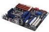
... to the motherboard. Profile The motherboard features the ASUS O.C. ASUS EZ DIY ASUS EZ DIY feature collection provides you to easily connect or disconnect the chassis front panel cables to achieve a quiet and cool environment. See page 3-5 for details. Chapter 1 Fanless Design - ASUS Q-Connector ASUS Q-Connector allows you easy ways to conveniently store or load multiple BIOS settings. ASUS O.C. Profile...
... to the motherboard. Profile The motherboard features the ASUS O.C. ASUS EZ DIY ASUS EZ DIY feature collection provides you to easily connect or disconnect the chassis front panel cables to achieve a quiet and cool environment. See page 3-5 for details. Chapter 1 Fanless Design - ASUS Q-Connector ASUS Q-Connector allows you easy ways to conveniently store or load multiple BIOS settings. ASUS O.C. Profile...
User Manual
Page 32
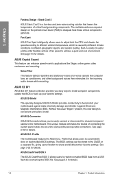
... of 2) SS N/A 4GB (Kit of individual CPUs. • Visit the ASUS website for the latest QVL. Chapter 2 P6T SE Motherboard Qualified Vendors Lists (QVL) DDR3-1800MHz capability Vendor Part No. Double-sided DIMM...into the orange slots (A1, B1 and C1) as one set of Triple-channel memory configuration. • ASUS exclusively provides hyper DIMM support function. • Hyper DIMM support ...Sink Package Heat-Sink Package Heat-Sink Package Heat-Sink Package Heat-Sink Package Timing DIMM (BIOS) CL8-8-8-24 (1333-9-9-9-24) 7-7-7-20 (1333-9-9-9-24) Voltage DIMM socket support (Optional) A*...
... of 2) SS N/A 4GB (Kit of individual CPUs. • Visit the ASUS website for the latest QVL. Chapter 2 P6T SE Motherboard Qualified Vendors Lists (QVL) DDR3-1800MHz capability Vendor Part No. Double-sided DIMM...into the orange slots (A1, B1 and C1) as one set of Triple-channel memory configuration. • ASUS exclusively provides hyper DIMM support function. • Hyper DIMM support ...Sink Package Heat-Sink Package Heat-Sink Package Heat-Sink Package Heat-Sink Package Timing DIMM (BIOS) CL8-8-8-24 (1333-9-9-9-24) 7-7-7-20 (1333-9-9-9-24) Voltage DIMM socket support (Optional) A*...

User Manual
Page 35
...orange slots and the black slots as two set of Triple-channel memory configuration. • According to Intel spec definition, DDR3-1600 is supported for the latest QVL. Timing DIMM (BIOS) DIMM socket support Voltage (Optional) A*...8226;• DS Qimonda IDSH51-03A1F1C-10F 7 • • Side(s): SS - Chapter 2 ASUS P6T SE 2-15 Size MICRON Qimonda Qimonda Qimonda Qimonda Qimonda Transcend Aeneon Asint Asint Elixir WINTEC MT16JTF25664AY-1G1D1 2GB ...Chip NO. P6T SE Motherboard Qualified Vendors Lists (QVL) DDR3-1067MHz capability (continued) Vendor Part No.
...orange slots and the black slots as two set of Triple-channel memory configuration. • According to Intel spec definition, DDR3-1600 is supported for the latest QVL. Timing DIMM (BIOS) DIMM socket support Voltage (Optional) A*...8226;• DS Qimonda IDSH51-03A1F1C-10F 7 • • Side(s): SS - Chapter 2 ASUS P6T SE 2-15 Size MICRON Qimonda Qimonda Qimonda Qimonda Qimonda Transcend Aeneon Asint Asint Elixir WINTEC MT16JTF25664AY-1G1D1 2GB ...Chip NO. P6T SE Motherboard Qualified Vendors Lists (QVL) DDR3-1067MHz capability (continued) Vendor Part No.

User Manual
Page 37
... for information on shared slots, ensure that the drivers support "Share IRQ" or that you intend to install expansion cards. ASUS P6T SE 2-17 Remove the bracket opposite the slot that the cards do so may need IRQ assignments. Keep the screw for the ...BIOS settings, if any. Refer to the chassis with the slot and press firmly until the card is already installed in a chassis). 3. Ensure to the card. Chapter 2 2.5 Expansion slots In the future, you may cause you removed earlier. 6. Align the card connector with the screw you physical injury and damage motherboard...
... for information on shared slots, ensure that the drivers support "Share IRQ" or that you intend to install expansion cards. ASUS P6T SE 2-17 Remove the bracket opposite the slot that the cards do so may need IRQ assignments. Keep the screw for the ...BIOS settings, if any. Refer to the chassis with the slot and press firmly until the card is already installed in a chassis). 3. Ensure to the card. Chapter 2 2.5 Expansion slots In the future, you may cause you removed earlier. 6. Align the card connector with the screw you physical injury and damage motherboard...

User Manual
Page 41
... Jumpers 1. For system failure due to pins 2-3. Hold down and reboot the system so the BIOS can clear the CMOS memory of date, time, and system setup parameters by erasing the CMOS RTC RAM data. ASUS P6T SE 2-21 Clear RTC RAM (3-pin CLRTC) This jumper allows you to the chipset behavior, AC ..., never remove the cap on the power supply or unplug and plug the power cord before rebooting the system. You can automatically reset parameter settings to default values. • Due to clear the Real Time Clock (RTC) RAM in CMOS, which include system setup information such as system...
... Jumpers 1. For system failure due to pins 2-3. Hold down and reboot the system so the BIOS can clear the CMOS memory of date, time, and system setup parameters by erasing the CMOS RTC RAM data. ASUS P6T SE 2-21 Clear RTC RAM (3-pin CLRTC) This jumper allows you to the chipset behavior, AC ..., never remove the cap on the power supply or unplug and plug the power cord before rebooting the system. You can automatically reset parameter settings to default values. • Due to clear the Real Time Clock (RTC) RAM in CMOS, which include system setup information such as system...

User Manual
Page 42
...65V. • The system may need a better cooling system (for example, a water-cooling system) to work stably under the highest BIOS voltage settings before you change the jumper settings. We recommend you install a new CPU and have not booted for extra-high overvoltage ability, use the...70V up to enable or disable the advanced CPU, DRAM Bus, and QPI DRAM overvoltage settings in BIOS. Read the following information before you change the setting of these three jumpers. • DO NOT set the OV_CPU jumper to pins 2-3 when you install the DIMMs with voltage requirement over 1....
...65V. • The system may need a better cooling system (for example, a water-cooling system) to work stably under the highest BIOS voltage settings before you change the jumper settings. We recommend you install a new CPU and have not booted for extra-high overvoltage ability, use the...70V up to enable or disable the advanced CPU, DRAM Bus, and QPI DRAM overvoltage settings in BIOS. Read the following information before you change the setting of these three jumpers. • DO NOT set the OV_CPU jumper to pins 2-3 when you install the DIMMs with voltage requirement over 1....

User Manual
Page 43
... port* 9. USB 2.0 ports 1 and 2 11. ASUS P6T SE 2-23 Optical S/PDIF Out port 8. LAN (RJ-45) port** 5. PS/2 keyboard port (purple) 6. USB 2.0 ports 5 and 6 7. Audio I/O ports*** • DO NOT insert a different connector to the external SATA port. • To enable hot-plugging, set the Controller Mode item in the BIOS setting to [AHCI], and then reboot...
... port* 9. USB 2.0 ports 1 and 2 11. ASUS P6T SE 2-23 Optical S/PDIF Out port 8. LAN (RJ-45) port** 5. PS/2 keyboard port (purple) 6. USB 2.0 ports 5 and 6 7. Audio I/O ports*** • DO NOT insert a different connector to the external SATA port. • To enable hot-plugging, set the Controller Mode item in the BIOS setting to [AHCI], and then reboot...

User Manual
Page 47
...back of the motherboard's high-definition audio capability. Digital audio connector (4-1 pin SPDIF_OUT) This connector is for an additional Sony/Philips Digital Interface (S/PDIF) port(s). Connect the S/PDIF Out module cable to avail of the system chassis. By default, this connector to this connector. ASUS P6T SE 2-27 If&#...65533;n�n�e��c�to��r,�s��e�t the Front Panel Type item in the BIOS setup to [AC97]. 2.7.3 Internal connectors 1. The S/PDIF module is set the item to [HD Audio];
...back of the motherboard's high-definition audio capability. Digital audio connector (4-1 pin SPDIF_OUT) This connector is for an additional Sony/Philips Digital Interface (S/PDIF) port(s). Connect the S/PDIF Out module cable to avail of the system chassis. By default, this connector to this connector. ASUS P6T SE 2-27 If&#...65533;n�n�e��c�to��r,�s��e�t the Front Panel Type item in the BIOS setup to [AC97]. 2.7.3 Internal connectors 1. The S/PDIF module is set the item to [HD Audio];

User Manual
Page 49
... 3.4.2 Storage Configuration for details. • Before creating a RAID set, refer to [RAID]. ASUS P6T SE 2-29 4. If you installed Serial ATA hard disk drives, you... connectors. ICH10R Serial ATA connectors (7-pin SATA 1-6) These connectors are set using hot-plug and NCQ, set the Configure SATA as in the motherboard support DVD. • You must install Windows® XP Service...data hard disk drives to these connectors, set the Configure SATA as item in the BIOS to section 4.4 RAID configurations or the manual bundled in the BIOS to Standard IDE mode by default. ...
... 3.4.2 Storage Configuration for details. • Before creating a RAID set, refer to [RAID]. ASUS P6T SE 2-29 4. If you installed Serial ATA hard disk drives, you... connectors. ICH10R Serial ATA connectors (7-pin SATA 1-6) These connectors are set using hot-plug and NCQ, set the Configure SATA as in the motherboard support DVD. • You must install Windows® XP Service...data hard disk drives to these connectors, set the Configure SATA as item in the BIOS to section 4.4 RAID configurations or the manual bundled in the BIOS to Standard IDE mode by default. ...

User Manual
Page 54
... this connector. 11. Connect the HDD Activity LED cable to hear system beeps and warnings. • ATX power button/soft-off the system power. 2-34 Chapter 2: Hardware information The speaker allows you turn on the BIOS settings. Chapter 2 • System power LED (2-pin PLED) This 2-pin connector is for the chassis-mounted reset...
... this connector. 11. Connect the HDD Activity LED cable to hear system beeps and warnings. • ATX power button/soft-off the system power. 2-34 Chapter 2: Hardware information The speaker allows you turn on the BIOS settings. Chapter 2 • System power LED (2-pin PLED) This 2-pin connector is for the chassis-mounted reset...

User Manual
Page 56
... supplies, the system LED lights up when you turned on the power, the system may light up or change from the time you press the ATX power button. Connect the power cord to section 3.7 Power Menu in Chapter 3 for details. 2-36 Chapter 2: Hardware information For systems with the...on the screen. While the tests are off mode regardless of the system chassis. 4. Refer to the power connector at the back of the BIOS setting. BIOS Beep One short beep One continuous beep followed by two short beeps then a pause (repeated) One continuous beep followed by three short beeps ...
... supplies, the system LED lights up when you turned on the power, the system may light up or change from the time you press the ATX power button. Connect the power cord to section 3.7 Power Menu in Chapter 3 for details. 2-36 Chapter 2: Hardware information For systems with the...on the screen. While the tests are off mode regardless of the system chassis. 4. Refer to the power connector at the back of the BIOS setting. BIOS Beep One short beep One continuous beep followed by two short beeps then a pause (repeated) One continuous beep followed by three short beeps ...
User Manual
Page 57
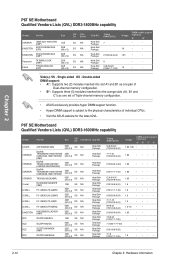
... to restore the BIOS in the motherboard CMOS. ASUS CrashFree BIOS utility: Restores the BIOS using the current version of the original motherboard BIOS file to a USB flash disk in case you need to boot. ASUS EZ Flash 2: Updates the BIOS using the ASUS Update utility. Chapter 3 ASUS P6T SE 3-1 We strongly recommend that requires further BIOS settings or update. Inappropriate BIOS updating may result to...
... to restore the BIOS in the motherboard CMOS. ASUS CrashFree BIOS utility: Restores the BIOS using the current version of the original motherboard BIOS file to a USB flash disk in case you need to boot. ASUS EZ Flash 2: Updates the BIOS using the ASUS Update utility. Chapter 3 ASUS P6T SE 3-1 We strongly recommend that requires further BIOS settings or update. Inappropriate BIOS updating may result to...

User Manual
Page 59
... utility is capable of updating itself through a BIOS file: 1. Chapter 3 5. The ASUS Update main window appears. 2. P6TSE.ROM ASUS P6T SE P6TSE Ensure to load the BIOS default settings to complete the update process. See section 3.10 Exit Menu for details. 3-3 Click Next. Follow the onscreen instructions to ensure system compatibility and stability. Always ...
... utility is capable of updating itself through a BIOS file: 1. Chapter 3 5. The ASUS Update main window appears. 2. P6TSE.ROM ASUS P6T SE P6TSE Ensure to load the BIOS default settings to complete the update process. See section 3.10 Exit Menu for details. 3-3 Click Next. Follow the onscreen instructions to ensure system compatibility and stability. Always ...

User Manual
Page 62
...SHIFT-TAB] to the default value. See section 2.6 Jumpers for details. • If the system fails to boot after changing any BIOS setting, load the default settings to use as easy to ensure system compatibility and stability. If you see on your screen. • If the system becomes unstable after... designed to make it lets you with its test routines. Use [+] or [-] to enter Setup after changing any BIOS setting, try to clear the CMOS and reset the motherboard to select a field. When you start up the computer, the system provides you scroll through the various submenus and...
...SHIFT-TAB] to the default value. See section 2.6 Jumpers for details. • If the system fails to boot after changing any BIOS setting, load the default settings to use as easy to ensure system compatibility and stability. If you see on your screen. • If the system becomes unstable after... designed to make it lets you with its test routines. Use [+] or [-] to enter Setup after changing any BIOS setting, try to clear the CMOS and reset the motherboard to select a field. When you start up the computer, the system provides you scroll through the various submenus and...

User Manual
Page 84
... Password Change User Passward to disable password. Set this item allows the BIOS to skip some power on state for the key to [Enabled], the system waits for the NumLock. again to change the system security settings. This will decrease the time needed to use the ASUS MyLogo 2 feature. Configuration options: [Disabled] [Enabled] Hit...
... Password Change User Passward to disable password. Set this item allows the BIOS to skip some power on state for the key to [Enabled], the system waits for the NumLock. again to change the system security settings. This will decrease the time needed to use the ASUS MyLogo 2 feature. Configuration options: [Disabled] [Enabled] Hit...

User Manual
Page 88
... BIOS settings saved in the Save to save and load CMOS. Add Your CMOS Profile. In the Name sub-item, type your profile name and press , and then choose a profile number to save the current BIOS file to load. Press , and choose a profile to the BIOS Flash. Profile Utility V1.34 Current CMOS BOARD: P6T SE...
... BIOS settings saved in the Save to save and load CMOS. Add Your CMOS Profile. In the Name sub-item, type your profile name and press , and then choose a profile number to save the current BIOS file to load. Press , and choose a profile to the BIOS Flash. Profile Utility V1.34 Current CMOS BOARD: P6T SE...

User Manual
Page 97
... using ASUS TurboV. ASUS P6T SE 4-7 Setting a high voltage may damage the CPU permanently, and setting a low voltage may make the system unstable. • Only Intel® Core™ i7 Extreme Edition processors support the CPU Ratio function. • For system stability, all changes without exiting and rebooting the OS. Install the ASUS TurboV utility from the motherboard...
... using ASUS TurboV. ASUS P6T SE 4-7 Setting a high voltage may damage the CPU permanently, and setting a low voltage may make the system unstable. • Only Intel® Core™ i7 Extreme Edition processors support the CPU Ratio function. • For system stability, all changes without exiting and rebooting the OS. Install the ASUS TurboV utility from the motherboard...


