
User Manual
Page 25
PWR Ground Reset Ground 10-1 pin IDE_LED RESET PWRSW * Requires an ATX power supply. 紅色 1 表示 PIN1 的位置 PLED+ PLEDPWR GND IDELED+ IDELED- Ground Reset PWR LED PWR BTN M2N-X F_PANEL HD LED RESET...1 2. 若 LED PIN1)。 3. SPEAKER、RESET 與 PWRSW IDE_LED 與 PLED PIN1 PIN1 4 25 1.8 1 RESET(Reset Switch PLED(Power LED PWRSW(Power Switch IDE_LED(IDE Hard Disk Active LED SPEAKER(Speaker Connector 20-8 pin PLED SPEAKER 1 PANEL1 PLED+ PLED+5V Ground Ground Speaker P5B-E ® IDE_LED...
PWR Ground Reset Ground 10-1 pin IDE_LED RESET PWRSW * Requires an ATX power supply. 紅色 1 表示 PIN1 的位置 PLED+ PLEDPWR GND IDELED+ IDELED- Ground Reset PWR LED PWR BTN M2N-X F_PANEL HD LED RESET...1 2. 若 LED PIN1)。 3. SPEAKER、RESET 與 PWRSW IDE_LED 與 PLED PIN1 PIN1 4 25 1.8 1 RESET(Reset Switch PLED(Power LED PWRSW(Power Switch IDE_LED(IDE Hard Disk Active LED SPEAKER(Speaker Connector 20-8 pin PLED SPEAKER 1 PANEL1 PLED+ PLED+5V Ground Ground Speaker P5B-E ® IDE_LED...

User Manual
Page 8
... safety • Before installing the motherboard and adding devices on a stable surface. • If you encounter technical problems with the package. • Before using , contact your local power company. • If the power supply is set to the correct voltage in your power supply is broken, do not try to... from the electrical outlet before relocating the system. • When adding or removing devices to or from the motherboard, ensure that all power cables are unplugged. • Seek professional assistance before the signal cables are connected. If you detect any area where ...
... safety • Before installing the motherboard and adding devices on a stable surface. • If you encounter technical problems with the package. • Before using , contact your local power company. • If the power supply is set to the correct voltage in your power supply is broken, do not try to... from the electrical outlet before relocating the system. • When adding or removing devices to or from the motherboard, ensure that all power cables are unplugged. • Seek professional assistance before the signal cables are connected. If you detect any area where ...

User Manual
Page 21
... any component, ensure that the ATX power supply is switched off or the power cord is ON, in sleep mode, or in soft-off mode. The illustration below shows the location of the following precautions before you install motherboard components or change any motherboard settings. • Unplug the power cord from the power supply. Chapter 2 ASUS P6T SE 2-1 Failure to do so...
... any component, ensure that the ATX power supply is switched off or the power cord is ON, in sleep mode, or in soft-off mode. The illustration below shows the location of the following precautions before you install motherboard components or change any motherboard settings. • Unplug the power cord from the power supply. Chapter 2 ASUS P6T SE 2-1 Failure to do so...

User Manual
Page 36
... notch so that it flips out with your fingers when pressing the retaining clips. Press the retaining clips outward to both the motherboard and the components. DO NOT force a DIMM into the socket 3 until the retaining clips snap back in only one direction. ... Chapter 2 Locked Retaining Clip 2.4.4 Removing a DIMM To remove a DIMM: 2 1. Simultaneously press the retaining clips outward to unplug the power supply before adding or removing DIMMs or other system components. To install a DIMM: 1. Remove the DIMM from the socket. 2-16 Chapter 2: Hardware information
... notch so that it flips out with your fingers when pressing the retaining clips. Press the retaining clips outward to both the motherboard and the components. DO NOT force a DIMM into the socket 3 until the retaining clips snap back in only one direction. ... Chapter 2 Locked Retaining Clip 2.4.4 Removing a DIMM To remove a DIMM: 2 1. Simultaneously press the retaining clips outward to unplug the power supply before adding or removing DIMMs or other system components. To install a DIMM: 1. Remove the DIMM from the socket. 2-16 Chapter 2: Hardware information

User Manual
Page 41
...need to clear the RTC when the system hangs due to the chipset behavior, AC power off and on the power supply or unplug and plug the power cord before rebooting the system. Turn OFF the computer and unplug the power cord. 2. Hold down and reboot the system so the BIOS can clear the CMOS... battery. • You do not help, remove the onboard battery and move the cap back to clear the CMOS RTC RAM data. 2.6 Jumpers 1. Plug the power cord and turn off is required to re-enter data. Shut down the key during the boot process and enter BIOS setup to enable C.P.R. ASUS P6T SE 2-21
...need to clear the RTC when the system hangs due to the chipset behavior, AC power off and on the power supply or unplug and plug the power cord before rebooting the system. Turn OFF the computer and unplug the power cord. 2. Hold down and reboot the system so the BIOS can clear the CMOS... battery. • You do not help, remove the onboard battery and move the cap back to clear the CMOS RTC RAM data. 2.6 Jumpers 1. Plug the power cord and turn off is required to re-enter data. Shut down the key during the boot process and enter BIOS setup to enable C.P.R. ASUS P6T SE 2-21

User Manual
Page 53
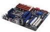
... Thermaltake W0083RE Thermaltake PUREPower-600AP Silverstone SST-ST75ZF EnerMAX EG701AX-VE (E)(24P) ASUS P6T SE 2-33 The power supply plugs are for details. • If you are uncertain about the minimum power supply requirement for your system, refer to connect the 4-pin / 8-pin EATX12 V power plug; ATX power connectors (24-pin EATXPWR; 8-pin EATX12V) These connectors are designed to ensure...
... Thermaltake W0083RE Thermaltake PUREPower-600AP Silverstone SST-ST75ZF EnerMAX EG701AX-VE (E)(24P) ASUS P6T SE 2-33 The power supply plugs are for details. • If you are uncertain about the minimum power supply requirement for your system, refer to connect the 4-pin / 8-pin EATX12 V power plug; ATX power connectors (24-pin EATXPWR; 8-pin EATX12V) These connectors are designed to ensure...

User Manual
Page 56
.... Follow the instructions in Chapter 3 for less than four seconds lets the system enter the soft-off the computer While the system is equipped with ATX power supplies, the system LED lights up . After making all switches are running, the BIOS beeps (see anything within 30 seconds from orange to enter the BIOS...
.... Follow the instructions in Chapter 3 for less than four seconds lets the system enter the soft-off the computer While the system is equipped with ATX power supplies, the system LED lights up . After making all switches are running, the BIOS beeps (see anything within 30 seconds from orange to enter the BIOS...

User Manual
Page 81
... +5VSB lead. Configuration options: [Disabled] [Enabled] Chapter 3 ASUS P6T SE 3-25 Configuration options: [Disabled] [Enabled] Power On By PCI Devices [Disabled] Allows you to enable or disable the PME to [Power Off], the system goes into either off state after an AC power loss. This feature requires an ATX power supply that provides at least 1A on the +5VSB...
... +5VSB lead. Configuration options: [Disabled] [Enabled] Chapter 3 ASUS P6T SE 3-25 Configuration options: [Disabled] [Enabled] Power On By PCI Devices [Disabled] Allows you to enable or disable the PME to [Power Off], the system goes into either off state after an AC power loss. This feature requires an ATX power supply that provides at least 1A on the +5VSB...

User Manual
Page 107
... driver from the AMD website (www.amd.com). • Ensure that your power supply unit (PSU) can provide at least the minimum power required by Windows® Vista operating system only. • Visit the ATI Game...ASUS P6T SE 5-1 Turn off your current graphics card driver/s. 4. See page 2-33 for details. • The ATI Triple CrossFireX technology is currently supported by your system. Select your computer. For Windows Vista, select Uninstall. 5. Chapter 5 Chapter 5: 5.1 Chapter 5 ATI® CrossFireX™ technology support ATI® CrossFireX™ technology The motherboard...
... driver from the AMD website (www.amd.com). • Ensure that your power supply unit (PSU) can provide at least the minimum power required by Windows® Vista operating system only. • Visit the ATI Game...ASUS P6T SE 5-1 Turn off your current graphics card driver/s. 4. See page 2-33 for details. • The ATI Triple CrossFireX technology is currently supported by your system. Select your computer. For Windows Vista, select Uninstall. 5. Chapter 5 Chapter 5: 5.1 Chapter 5 ATI® CrossFireX™ technology support ATI® CrossFireX™ technology The motherboard...

User Manual
Page 108
..., refer to the goldfingers on the slots. 4. Different types of graphics cards will not work together properly. • The motherboard layout of the PCIEX16 slots recommended for multigraphics card installation. 3. Insert the two graphics card into the PCIEX16 slots. Align and... properly seated on each graphics card. Chapter 5 5.2 Installing CrossFireX™ graphics cards • Ensure that your power supply unit (PSU) can provide at least the minimum power required by your system. • We recommend that you install additional chassis fans for better thermal environment. •...
..., refer to the goldfingers on the slots. 4. Different types of graphics cards will not work together properly. • The motherboard layout of the PCIEX16 slots recommended for multigraphics card installation. 3. Insert the two graphics card into the PCIEX16 slots. Align and... properly seated on each graphics card. Chapter 5 5.2 Installing CrossFireX™ graphics cards • Ensure that your power supply unit (PSU) can provide at least the minimum power required by your system. • We recommend that you install additional chassis fans for better thermal environment. •...

User Manual
Page 109
... CrossFireX-ready graphics cards. 2. Connect three independent auxiliary power sources from the power supply to the graphics card. Ensure that the connectors are properly seated on each graphics card. If your motherboard has more than three PCIEX16 slots, refer to the graphics card. 5.2.2 Triple CrossFireX installation 1. ASUS P6T SE 5-3 Insert the three graphics card into the PCIEX16...
... CrossFireX-ready graphics cards. 2. Connect three independent auxiliary power sources from the power supply to the graphics card. Ensure that the connectors are properly seated on each graphics card. If your motherboard has more than three PCIEX16 slots, refer to the graphics card. 5.2.2 Triple CrossFireX installation 1. ASUS P6T SE 5-3 Insert the three graphics card into the PCIEX16...


