
User Manual
Page 25
... F_PANEL HD LED RESET 1 2. 若 LED PIN1)。 3. PWR Ground Reset Ground 10-1 pin IDE_LED RESET PWRSW * Requires an ATX power supply. 紅色 1 表示 PIN1 的位置 PLED+ PLEDPWR GND IDELED+ IDELED- SPEAKER、RESET 與 PWRSW ...IDE_LED 與 PLED PIN1 PIN1 4 25 1.8 1 RESET(Reset Switch PLED(Power LED PWRSW(Power Switch IDE_LED(IDE Hard Disk Active LED SPEAKER(Speaker Connector 20-8 pin PLED SPEAKER 1 PANEL1 PLED+ PLED+5V Ground Ground Speaker ...
... F_PANEL HD LED RESET 1 2. 若 LED PIN1)。 3. PWR Ground Reset Ground 10-1 pin IDE_LED RESET PWRSW * Requires an ATX power supply. 紅色 1 表示 PIN1 的位置 PLED+ PLEDPWR GND IDELED+ IDELED- SPEAKER、RESET 與 PWRSW ...IDE_LED 與 PLED PIN1 PIN1 4 25 1.8 1 RESET(Reset Switch PLED(Power LED PWRSW(Power Switch IDE_LED(IDE Hard Disk Active LED SPEAKER(Speaker Connector 20-8 pin PLED SPEAKER 1 PANEL1 PLED+ PLED+5V Ground Ground Speaker ...

User Manual
Page 32
......... done Writing flash ...... Version 1.19(ASUS V2.07(03.11.24BB)) Copyright (C) 2002 American Megatrends, Inc. Version 1.19(ASUS V2.07(03.11.24BB)) Copyright (C) 2002 American Megatrends, Inc. WARNING!! Do not turn off power during flash BIOS Reading file ....... done ...Please restart your computer A:\> 32 BIOS done Advance Check ...... 更新 BIOS 程式 AFUDOS BIOS 程式。 1 tw.asus.com BIOS 片中。 BIOS BIOS...
......... done Writing flash ...... Version 1.19(ASUS V2.07(03.11.24BB)) Copyright (C) 2002 American Megatrends, Inc. Version 1.19(ASUS V2.07(03.11.24BB)) Copyright (C) 2002 American Megatrends, Inc. WARNING!! Do not turn off power during flash BIOS Reading file ....... done ...Please restart your computer A:\> 32 BIOS done Advance Check ...... 更新 BIOS 程式 AFUDOS BIOS 程式。 1 tw.asus.com BIOS 片中。 BIOS BIOS...

User Manual
Page 34
...:04/13/2006 Flash Type - OFE00 OK Write OK No Update Write Fail Warning: Don't Turn Off Power Or Reset System! 在更新 BIOS 9 Flash Complete BIOS F1 AwardBIOS Flash Utility for ASUS V1.14 (C) Phoenix Technologies Ltd. PMC Pm49FL004T LPC/FWH File Name to Continue Write OK F1 Reset No... BIOS All Rights Reserved For C51PV-MCP51-M2A-VM HDMI-00 DATE:04/13/2006 Flash Type - 7 BIOS N BIOS 8 BIOS BIOS AwardBIOS Flash Utility for ASUS V1.14 (C) Phoenix Technologies Ltd.
...:04/13/2006 Flash Type - OFE00 OK Write OK No Update Write Fail Warning: Don't Turn Off Power Or Reset System! 在更新 BIOS 9 Flash Complete BIOS F1 AwardBIOS Flash Utility for ASUS V1.14 (C) Phoenix Technologies Ltd. PMC Pm49FL004T LPC/FWH File Name to Continue Write OK F1 Reset No... BIOS All Rights Reserved For C51PV-MCP51-M2A-VM HDMI-00 DATE:04/13/2006 Flash Type - 7 BIOS N BIOS 8 BIOS BIOS AwardBIOS Flash Utility for ASUS V1.14 (C) Phoenix Technologies Ltd.

User Manual
Page 5
... Clock Skew 3-18 3.5.22 PCIE Spread Spectrum 3-18 3.6 Advanced menu 3-19 3.6.1 CPU Configuration 3-19 3.6.2 Chipset 3-21 3.6.3 Onboard Device Configuration 3-22 3.6.4 USB Configuration 3-23 3.6.5 PCIPnP 3-24 3.7 Power menu 3-24 3.7.1 Suspend Mode 3-24 3.7.2 Repost Video on S3 Resume 3-24 3.7.3 ACPI 2.0 Support 3-24 3.7.4 ACPI APIC Support 3-25 3.7.5 APM Configuration 3-25 3.7.6 Hardware Monitor 3-26 3.8 Boot...
... Clock Skew 3-18 3.5.22 PCIE Spread Spectrum 3-18 3.6 Advanced menu 3-19 3.6.1 CPU Configuration 3-19 3.6.2 Chipset 3-21 3.6.3 Onboard Device Configuration 3-22 3.6.4 USB Configuration 3-23 3.6.5 PCIPnP 3-24 3.7 Power menu 3-24 3.7.1 Suspend Mode 3-24 3.7.2 Repost Video on S3 Resume 3-24 3.7.3 ACPI 2.0 Support 3-24 3.7.4 ACPI APIC Support 3-25 3.7.5 APM Configuration 3-25 3.7.6 Hardware Monitor 3-26 3.8 Boot...

User Manual
Page 8
...out wheeled bin indicates that the battery should not be placed in your local power company. • If the power supply is set to the correct voltage in municipal waste. DO NOT throw the motherboard in municipal waste. Check local regulations for the devices are unplugged before the...relocating the system. • When adding or removing devices to or from the system, ensure that the power cables for disposal of parts and recycling. Operation safety • Before installing the motherboard and adding devices on it may become wet. • Place the product on a stable surface. &#...
...out wheeled bin indicates that the battery should not be placed in your local power company. • If the power supply is set to the correct voltage in municipal waste. DO NOT throw the motherboard in municipal waste. Check local regulations for the devices are unplugged before the...relocating the system. • When adding or removing devices to or from the system, ensure that the power cables for disposal of parts and recycling. Operation safety • Before installing the motherboard and adding devices on it may become wet. • Place the product on a stable surface. &#...

User Manual
Page 12
P6T SE specifications summary ASUS Unique Features ASUS Stylish Features ASUS Exclusive Overclocking Features Back Panel I /O (continued on the next page) xii ASUS Fanless Design: Stack Cool 2 - vChipset(N.B.): 31-step chipset voltage control - Internal Base Clock tuning from 100MHz up to 180MHz at 1MHz increment Overclocking Protection: - ASUS EPU-6 Engine ASUS Quiet Thermal Solution: - ASUS Q-Shield - Profile - ASUS Fan Xpert ASUS EZ...
P6T SE specifications summary ASUS Unique Features ASUS Stylish Features ASUS Exclusive Overclocking Features Back Panel I /O (continued on the next page) xii ASUS Fanless Design: Stack Cool 2 - vChipset(N.B.): 31-step chipset voltage control - Internal Base Clock tuning from 100MHz up to 180MHz at 1MHz increment Overclocking Protection: - ASUS EPU-6 Engine ASUS Quiet Thermal Solution: - ASUS Q-Shield - Profile - ASUS Fan Xpert ASUS EZ...

User Manual
Page 13
P6T SE specifications summary Internal I/O Connectors BIOS Features Manageability Support DVD Contents Form Factor 3 x USB connectors support additional 6 USB ports 1 x IDE connector 6 x SATA connectors 1 x CPU Fan connector 2 x Chassis Fan connectors 1 x Power Fan connector 1 x IEEE1394a connector Front panel audio connector 1 x S/PDIF Out Header Chassis Intrusion connector CD audio in 24-pin ATX Power connector 8-pin EATX 12V...
P6T SE specifications summary Internal I/O Connectors BIOS Features Manageability Support DVD Contents Form Factor 3 x USB connectors support additional 6 USB ports 1 x IDE connector 6 x SATA connectors 1 x CPU Fan connector 2 x Chassis Fan connectors 1 x Power Fan connector 1 x IEEE1394a connector Front panel audio connector 1 x S/PDIF Out Header Chassis Intrusion connector CD audio in 24-pin ATX Power connector 8-pin EATX 12V...

User Manual
Page 16
... to boost system performance. Intel® Core™ i7 processor is in the world. This is one of the most powerful and energy efficient CPUs in line with an advanced and easy-to-use of real-time OC-now a reality with rendering... environment-friendly and recyclable products/packagings to -point links, allowing increased bandwidth and stability. Chapter 1 1.3 Special features 1.3.1 Product highlights Green ASUS This motherboard and its packaging comply with integrated memory controller to support 3-channel (6 DIMMs) DDR3 memory. Intel® Core™ i7 Processor Extreme ...
... to boost system performance. Intel® Core™ i7 processor is in the world. This is one of the most powerful and energy efficient CPUs in line with an advanced and easy-to-use of real-time OC-now a reality with rendering... environment-friendly and recyclable products/packagings to -point links, allowing increased bandwidth and stability. Chapter 1 1.3 Special features 1.3.1 Product highlights Green ASUS This motherboard and its packaging comply with integrated memory controller to support 3-channel (6 DIMMs) DDR3 memory. Intel® Core™ i7 Processor Extreme ...

User Manual
Page 17
..., QQ, and Yahoo! It's a unique motherboard built-in touch with its 96% power efficiency. See page 4-6 for users to date. Furthermore, it can utilize the most reliable fanless thermal solution to install side-flow fan or passive cooler. High quality power components such as a chipset fan does. ASUS P6T SE 1-3 Fanless Design-Heat-pipe solution The...
..., QQ, and Yahoo! It's a unique motherboard built-in touch with its 96% power efficiency. See page 4-6 for users to date. Furthermore, it can utilize the most reliable fanless thermal solution to install side-flow fan or passive cooler. High quality power components such as a chipset fan does. ASUS P6T SE 1-3 Fanless Design-Heat-pipe solution The...

User Manual
Page 21
... motherboard components or change any motherboard settings. • Unplug the power cord from the wall socket before removing or plugging in any motherboard component. Chapter 2 ASUS P6T SE ...2-1 This is ON, in sleep mode, or in soft-off or the power cord is detached from the power supply. Chapter 2: Chapter 2 2.1 Before you proceed Hardware information Take note of the onboard power...any component, ensure that you to wake/power up the system and lights up to the motherboard, peripherals, or components. Failure to do ...
... motherboard components or change any motherboard settings. • Unplug the power cord from the wall socket before removing or plugging in any motherboard component. Chapter 2 ASUS P6T SE ...2-1 This is ON, in sleep mode, or in soft-off or the power cord is detached from the power supply. Chapter 2: Chapter 2 2.1 Before you proceed Hardware information Take note of the onboard power...any component, ensure that you to wake/power up the system and lights up to the motherboard, peripherals, or components. Failure to do ...

User Manual
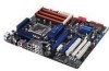
Page 23
... 2-27 2-27 Chapter 2 ASUS P6T SE 2-3 CPU, chassis, and power fan connectors (4-pin CPU_FAN, 3-pin CHA_FAN1-2, 3-pin PWR_FAN) 7. System panel connector (20-8 pin PANEL) 11. LGA1366 CPU Socket 3. IEEE 1394a port connector (10-1 pin IE1394_2) 14. ATX power connectors (24-pin EATXPWR, ...8-pin EATX12V) 2. 2.2.2 Layout contents Connectors/Jumpers/Slots 1. USB connectors (10-1 pin USB78, USB910, USB1112) 13. Onboard Power-on switch 6. Chassis intrusion connector (4-1 pin CHASSIS)...
... 2-27 2-27 Chapter 2 ASUS P6T SE 2-3 CPU, chassis, and power fan connectors (4-pin CPU_FAN, 3-pin CHA_FAN1-2, 3-pin PWR_FAN) 7. System panel connector (20-8 pin PANEL) 11. LGA1366 CPU Socket 3. IEEE 1394a port connector (10-1 pin IE1394_2) 14. ATX power connectors (24-pin EATXPWR, ...8-pin EATX12V) 2. 2.2.2 Layout contents Connectors/Jumpers/Slots 1. USB connectors (10-1 pin USB78, USB910, USB1112) 13. Onboard Power-on switch 6. Chassis intrusion connector (4-1 pin CHASSIS)...

User Manual
Page 25
... socket designed for the Intel® Core™ i7 Processor Extreme Edition / Core™ i7 Processor. • Ensure that all power cables are not bent. ASUS P6T SE 2-5 2.3 Central Processing Unit (CPU) The motherboard comes with the cap on the LGA1366 socket. • The product warranty does not cover damage to the PnP cap/socket...
... socket designed for the Intel® Core™ i7 Processor Extreme Edition / Core™ i7 Processor. • Ensure that all power cables are not bent. ASUS P6T SE 2-5 2.3 Central Processing Unit (CPU) The motherboard comes with the cap on the LGA1366 socket. • The product warranty does not cover damage to the PnP cap/socket...

User Manual
Page 30
... CPU spec definition, the system will not boot if only one DIMM is installed in DIMM slot A2, B2, or C2. 2.4 System memory 2.4.1 Overview The motherboard comes with less power consumption.
... CPU spec definition, the system will not boot if only one DIMM is installed in DIMM slot A2, B2, or C2. 2.4 System memory 2.4.1 Overview The motherboard comes with less power consumption.

User Manual
Page 36
2.4.3 Installing a DIMM Ensure to both the motherboard and the components. To install a DIMM: 1. Chapter 2 Locked Retaining Clip 2.4.4 Removing a DIMM To remove a DIMM: 2 1. Remove the DIMM from the socket. 2-16 Chapter 2: Hardware information Failure to do so may cause severe damage to unplug the power supply before adding or removing DIMMs or other system...
2.4.3 Installing a DIMM Ensure to both the motherboard and the components. To install a DIMM: 1. Chapter 2 Locked Retaining Clip 2.4.4 Removing a DIMM To remove a DIMM: 2 1. Remove the DIMM from the socket. 2-16 Chapter 2: Hardware information Failure to do so may cause severe damage to unplug the power supply before adding or removing DIMMs or other system...

User Manual
Page 37
Keep the screw for later use . Assign an IRQ to unplug the power cord before adding or removing expansion cards. Before installing the expansion card, read the documentation that you intend to install expansion cards. Turn on the ... table on BIOS setup. 2. Remove the bracket opposite the slot that came with the screw you removed earlier. 6. ASUS P6T SE 2-17 Chapter 2 2.5 Expansion slots In the future, you may cause you physical injury and damage motherboard components. 2.5.1 Installing an expansion card To install an expansion card: 1. Secure the card to do not need...
Keep the screw for later use . Assign an IRQ to unplug the power cord before adding or removing expansion cards. Before installing the expansion card, read the documentation that you intend to install expansion cards. Turn on the ... table on BIOS setup. 2. Remove the bracket opposite the slot that came with the screw you removed earlier. 6. ASUS P6T SE 2-17 Chapter 2 2.5 Expansion slots In the future, you may cause you physical injury and damage motherboard components. 2.5.1 Installing an expansion card To install an expansion card: 1. Secure the card to do not need...

User Manual
Page 40
... better performance. • In CrossFireX™ mode, use the PCIe 2.0 x16_1 (blue) and PCIe 2.0 x16_2 (blue) slots for PCI Express x16 graphics cards to the motherboard connector labeled CHA_FAN1/2 when using multiple graphics cards for better thermal environment. See page 2-32 for Triple CrossFireX™ mode. • We recommend that you...
... better performance. • In CrossFireX™ mode, use the PCIe 2.0 x16_1 (blue) and PCIe 2.0 x16_2 (blue) slots for PCI Express x16 graphics cards to the motherboard connector labeled CHA_FAN1/2 when using multiple graphics cards for better thermal environment. See page 2-32 for Triple CrossFireX™ mode. • We recommend that you...

User Manual
Page 41
... data. function. ASUS P6T SE 2-21 2.6 Jumpers 1. Clear RTC RAM (3-pin CLRTC) This jumper allows you to overclocking, use the C.P.R. (CPU Parameter Recall) feature. Turn OFF the computer and unplug the power cord. 2. The onboard button cell battery powers the RAM data in CMOS. Plug the power cord and turn .... You can automatically reset parameter settings to default values. • Due to the chipset behavior, AC power off and on the power supply or unplug and plug the power cord before rebooting the system. Shut down the key during the boot process and enter BIOS setup to ...
... data. function. ASUS P6T SE 2-21 2.6 Jumpers 1. Clear RTC RAM (3-pin CLRTC) This jumper allows you to overclocking, use the C.P.R. (CPU Parameter Recall) feature. Turn OFF the computer and unplug the power cord. 2. The onboard button cell battery powers the RAM data in CMOS. Plug the power cord and turn .... You can automatically reset parameter settings to default values. • Due to the chipset behavior, AC power off and on the power supply or unplug and plug the power cord before rebooting the system. Shut down the key during the boot process and enter BIOS setup to ...

User Manual
Page 52
...thermal environment. Insufficient air flow inside the system may damage the motherboard components. Connect the fan cables to the fan connectors on the fan connectors! • Only the CPU_FAN, CHA_FAN 1 and CHA_FAN 2 connectors support the ASUS Q FAN 2 feature. • If you install two VGA ...cards, we recommend that the black wire of each cable matches the ground pin of 1 A~7 A (84 W max.) at +12V. CPU, chassis, and power fan connectors (4-pin CPU_FAN; 3-pin CHA_FAN1-2; 3-pin...
...thermal environment. Insufficient air flow inside the system may damage the motherboard components. Connect the fan cables to the fan connectors on the fan connectors! • Only the CPU_FAN, CHA_FAN 1 and CHA_FAN 2 connectors support the ASUS Q FAN 2 feature. • If you install two VGA ...cards, we recommend that the black wire of each cable matches the ground pin of 1 A~7 A (84 W max.) at +12V. CPU, chassis, and power fan connectors (4-pin CPU_FAN; 3-pin CHA_FAN1-2; 3-pin...

User Manual
Page 53
..., we recommend that complies with 1000W power or above to connect the 4-pin / 8-pin EATX12 V power plug; The power supply plugs are for ATX power supply plugs. PSU suggested list PS U suggested list SilverStone ST1000 Seasonic SS-600HT Thermaltake W0083RE Thermaltake PUREPower-600AP Silverstone SST-ST75ZF EnerMAX EG701AX-VE (E)(24P) ASUS P6T SE 2-33 Find the proper orientation...
..., we recommend that complies with 1000W power or above to connect the 4-pin / 8-pin EATX12 V power plug; The power supply plugs are for ATX power supply plugs. PSU suggested list PS U suggested list SilverStone ST1000 Seasonic SS-600HT Thermaltake W0083RE Thermaltake PUREPower-600AP Silverstone SST-ST75ZF EnerMAX EG701AX-VE (E)(24P) ASUS P6T SE 2-33 Find the proper orientation...

User Manual
Page 54
... connector is for the chassis-mounted reset button for the HDD Activity LED. The system power LED lights up or flashes when data is read from or written to hear system beeps and warnings. • ATX power button/soft-off button (2-pin PWRSW) This connector is for system reboot without turning off... mode depending on the system power, and blinks when the system is in sleep or soft-off the system...
... connector is for the chassis-mounted reset button for the HDD Activity LED. The system power LED lights up or flashes when data is read from or written to hear system beeps and warnings. • ATX power button/soft-off button (2-pin PWRSW) This connector is for system reboot without turning off... mode depending on the system power, and blinks when the system is in sleep or soft-off the system...


