
User Manual
Page 2
... after the period of International Business Machines. • Symbios is defaced or missing. Copyright © 1997 ASUSTeK COMPUTER INC. Product Name: P/I-P65UP8 Manual Revision: 1.03 Release Date: November 1997 2 ASUS P/I-P65UP8 User's Manual Product warranty or service will not be extended if: (1) the product is repaired, modified or altered, unless such repair, modification...
... after the period of International Business Machines. • Symbios is defaced or missing. Copyright © 1997 ASUSTeK COMPUTER INC. Product Name: P/I-P65UP8 Manual Revision: 1.03 Release Date: November 1997 2 ASUS P/I-P65UP8 User's Manual Product warranty or service will not be extended if: (1) the product is repaired, modified or altered, unless such repair, modification...

User Manual
Page 3
... Support Fax: +886-2-895-9254 BBS: +886-2-896-4667 Email: tsd@asus.com.tw WWW: www.asus.com.tw Gopher: gopher.asus.com.tw FTP: ftp.asus.com.tw/pub/ASUS ASUS COMPUTER INTERNATIONAL Marketing Info Address: 721 Charcot Avenue, San Jose, CA 95131,...ASUS COMPUTER GmbH Marketing Info Address: Harkort Str. 25, 40880 Ratingen, BRD, Germany Telephone: 49-2102-445011 Fax: 49-2102-442066 Email: info-ger@asus.com.tw Technical Support Hotline: 49-2102-499712 BBS: 49-2102-448690 Email: tsd-ger@asus.com.tw WWW: www.asuscom.de FTP: ftp.asuscom.de/pub/ASUSCOM ASUS P/I-P65UP8...
... Support Fax: +886-2-895-9254 BBS: +886-2-896-4667 Email: tsd@asus.com.tw WWW: www.asus.com.tw Gopher: gopher.asus.com.tw FTP: ftp.asus.com.tw/pub/ASUS ASUS COMPUTER INTERNATIONAL Marketing Info Address: 721 Charcot Avenue, San Jose, CA 95131,...ASUS COMPUTER GmbH Marketing Info Address: Harkort Str. 25, 40880 Ratingen, BRD, Germany Telephone: 49-2102-445011 Fax: 49-2102-442066 Email: info-ger@asus.com.tw Technical Support Hotline: 49-2102-499712 BBS: 49-2102-448690 Email: tsd-ger@asus.com.tw WWW: www.asuscom.de FTP: ftp.asuscom.de/pub/ASUSCOM ASUS P/I-P65UP8...

User Manual
Page 4
...INTRODUCTION 7 How this Manual is Organized 7 Item Checklist 7 Features of the ASUS Baseboard 9 III. Central Processing Unit 20 System Case 20 4. FEATURES 8 Parts of the ASUS P/I -P65UP8 User's Manual Expansion Cards 22 Expansion Card Installation Procedure 22 Assigning IRQs for... IBM OS/2 Video Driver Installation 39 AutoCAD Video Driver Installation 39 Microstation Video Driver Installation 39 4 ASUS P/I -P65UP8 Baseboard 8 II. INSTALLATION 10 ASUS Baseboard Layout 10 Installation Steps 12 1. System Memory (DRAM 18 DRAM Memory Installation Procedures 19 3. CONTENTS ...
...INTRODUCTION 7 How this Manual is Organized 7 Item Checklist 7 Features of the ASUS Baseboard 9 III. Central Processing Unit 20 System Case 20 4. FEATURES 8 Parts of the ASUS P/I -P65UP8 User's Manual Expansion Cards 22 Expansion Card Installation Procedure 22 Assigning IRQs for... IBM OS/2 Video Driver Installation 39 AutoCAD Video Driver Installation 39 Microstation Video Driver Installation 39 4 ASUS P/I -P65UP8 Baseboard 8 II. INSTALLATION 10 ASUS Baseboard Layout 10 Installation Steps 12 1. System Memory (DRAM 18 DRAM Memory Installation Procedures 19 3. CONTENTS ...
User Manual
Page 5
(This page was intentionally left blank.) ASUS P/I-P65UP8 User's Manual 5
(This page was intentionally left blank.) ASUS P/I-P65UP8 User's Manual 5
User Manual
Page 6
... that to which can radiate radio frequency energy and, if not installed and used in the Radio Interference Regulations of the Canadian Department of Communications. 6 ASUS P/I-P65UP8 User's Manual This equipment generates, uses and can be determined by turning the equipment off and on, the user is subject to the following measures...
... that to which can radiate radio frequency energy and, if not installed and used in the Radio Interference Regulations of the Canadian Department of Communications. 6 ASUS P/I-P65UP8 User's Manual This equipment generates, uses and can be determined by turning the equipment off and on, the user is subject to the following measures...

User Manual
Page 7
... (1) bag of spare jumpers (1) Motherboard User's Manual (1) SCSI Utilities User's Manual (1) C-P6ND or C-PKND CPU card (1) Infrared module (optional) ASUS P/I . INTRODUCTION (Manual / Checklist) I . Features: Information and specifications concerning this Manual is Organized This manual is complete. If you discover damaged ...or missing items, please contact your package is divided into the following sections: I -P65UP8 User's Manual 7 Introduction: Manual information and checklist II. INTRODUCTION How this product III. Installation: Instructions on setting up ...
... (1) bag of spare jumpers (1) Motherboard User's Manual (1) SCSI Utilities User's Manual (1) C-P6ND or C-PKND CPU card (1) Infrared module (optional) ASUS P/I . INTRODUCTION (Manual / Checklist) I . Features: Information and specifications concerning this Manual is Organized This manual is complete. If you discover damaged ...or missing items, please contact your package is divided into the following sections: I -P65UP8 User's Manual 7 Introduction: Manual information and checklist II. INTRODUCTION How this product III. Installation: Instructions on setting up ...

User Manual
Page 8
FEATURES Features of the ASUS P/I-P65UP8 Baseboard The P/I-P65UP8 is carefully designed for wireless file transfers and communication. 8 ASUS P/I /O: Provides two high-speed UART-compatible serial ports and one parallel port with soft-on/off features. • Versatile DRAM Memory Support: Supports eight ... C-P6ND CPU card. • ISA and PCI Expansion Slots: Provides three 16-bit ISA slots and seven 32-bit PCI slots. • Super Multi-I -P65UP8 User's Manual Supports two of 4MB, 8MB, 16MB, 32MB, 64MB, 128MB to form a memory size between 8MB to 1GB. Supports both AT and ATX power...
FEATURES Features of the ASUS P/I-P65UP8 Baseboard The P/I-P65UP8 is carefully designed for wireless file transfers and communication. 8 ASUS P/I /O: Provides two high-speed UART-compatible serial ports and one parallel port with soft-on/off features. • Versatile DRAM Memory Support: Supports eight ... C-P6ND CPU card. • ISA and PCI Expansion Slots: Provides three 16-bit ISA slots and seven 32-bit PCI slots. • Super Multi-I -P65UP8 User's Manual Supports two of 4MB, 8MB, 16MB, 32MB, 64MB, 128MB to form a memory size between 8MB to 1GB. Supports both AT and ATX power...

User Manual
Page 9
FEATURES (Parts of the ASUS Baseboard 4 Secondary PCI Slots 3 ISA Slots Onboard VGA memory sockets CPU Card Slot Intel i960RD Symbios SCSI Adaptec SCSI 72-pin SIMM I2O Memory Sockets ... future) SCSI Channel Connectors AT Power Connector AT Aux. II. Connector Infrared Module Support ATX Power Connector (8) 72-pin SIMM Floppy System Memory Connector Sockets ASUS P/I-P65UP8 User's Manual 9 Pwr. FEATURES Parts of Board) II.
FEATURES (Parts of the ASUS Baseboard 4 Secondary PCI Slots 3 ISA Slots Onboard VGA memory sockets CPU Card Slot Intel i960RD Symbios SCSI Adaptec SCSI 72-pin SIMM I2O Memory Sockets ... future) SCSI Channel Connectors AT Power Connector AT Aux. II. Connector Infrared Module Support ATX Power Connector (8) 72-pin SIMM Floppy System Memory Connector Sockets ASUS P/I-P65UP8 User's Manual 9 Pwr. FEATURES Parts of Board) II.
User Manual
Page 10
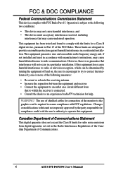
... 35 68 1 34 SIMM Socket 2 (Bank 1) SIMM Socket 1 (Bank 0) Battery Con. Universal Serial Bus 2Mbit Flash EEPROM (Programable BIOS) ASUS P/I /O Chip P8 P9 P10 ATX Power Input Main Power Input Aux. INSTALLATION ASUS Baseboard Layout Parallel Port Serial Ports COM 1 COM 2 ISA Slot 1 ISA Slot 2 ISA Slot 3 512KB DRAM for onboard VGA... PCI Slot 1 PCI Slot 2 PCI Slot 3 Secondary PCI Slot 1 Secondary PCI Slot 2 Secondary PCI Slot 3 Secondary PCI Slot 4 R Intel Chipset Secondary IDE Primary IDE Multi-I -P65UP8 User's Manual Keyboard CR2032 3Volts CMOS Power JP2 III.
... 35 68 1 34 SIMM Socket 2 (Bank 1) SIMM Socket 1 (Bank 0) Battery Con. Universal Serial Bus 2Mbit Flash EEPROM (Programable BIOS) ASUS P/I /O Chip P8 P9 P10 ATX Power Input Main Power Input Aux. INSTALLATION ASUS Baseboard Layout Parallel Port Serial Ports COM 1 COM 2 ISA Slot 1 ISA Slot 2 ISA Slot 3 512KB DRAM for onboard VGA... PCI Slot 1 PCI Slot 2 PCI Slot 3 Secondary PCI Slot 1 Secondary PCI Slot 2 Secondary PCI Slot 3 Secondary PCI Slot 4 R Intel Chipset Secondary IDE Primary IDE Multi-I -P65UP8 User's Manual Keyboard CR2032 3Volts CMOS Power JP2 III.
User Manual
Page 11
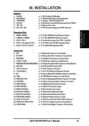
...-Wide SCSI Connectors 20) PWRCON, PWR-CON2 p. 32 AT Power Supply Connector (12-pin block) 21) ATXPOWER p. 32 ATX Power Supply Connector (20-pin block) ASUS P/I-P65UP8 User's Manual 11 III.
...-Wide SCSI Connectors 20) PWRCON, PWR-CON2 p. 32 AT Power Supply Connector (12-pin block) 21) ATXPOWER p. 32 ATX Power Supply Connector (20-pin block) ASUS P/I-P65UP8 User's Manual 11 III.

User Manual
Page 12
... precautions whenever you work on your computer when working on the bag that both of jumpers. To protect them against damage from the system. 12 ASUS P/I-P65UP8 User's Manual Hold components by the edges and try not to connect jumper pins (JP) on the baseboard. INSTALLATION (Jumpers) III. Install the Central Processing...
... precautions whenever you work on your computer when working on the bag that both of jumpers. To protect them against damage from the system. 12 ASUS P/I-P65UP8 User's Manual Hold components by the edges and try not to connect jumper pins (JP) on the baseboard. INSTALLATION (Jumpers) III. Install the Central Processing...
User Manual
Page 13
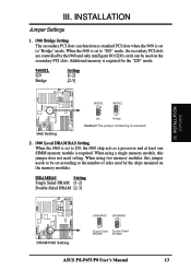
... memory modules. DRAMRAS Setting Single Sided DRAM [1-2] Double Sided DRAM [2-3] DRAM RAS Setting DRAMRAS 1 2 3 Single Sided DRAMS DRAMRAS 1 2 3 Double Sided DRAMS ASUS P/I /O (I2O) cards can function as a processor and at least one SIMM memory module is set according to "Bridge" mode. When using a single memory ...module, this jumper needs to be used by the i960 and only intelligent I -P65UP8 User's Manual 13 When the i960 is set to "I2O" mode, the secondary PCI slots are controlled by the chips mounted on the ...
... memory modules. DRAMRAS Setting Single Sided DRAM [1-2] Double Sided DRAM [2-3] DRAM RAS Setting DRAMRAS 1 2 3 Single Sided DRAMS DRAMRAS 1 2 3 Double Sided DRAMS ASUS P/I /O (I2O) cards can function as a processor and at least one SIMM memory module is set according to "Bridge" mode. When using a single memory ...module, this jumper needs to be used by the i960 and only intelligent I -P65UP8 User's Manual 13 When the i960 is set to "I2O" mode, the secondary PCI slots are controlled by the chips mounted on the ...
User Manual
Page 14
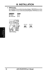
III. Set to SCSI ID 15, if you wish for the onboard Symbios 53C876 device to boot. INSTALLATION (Jumpers) 14 ASUS P/I-P65UP8 User's Manual INSTALLATION 3. 7880 ID Setting Set to SCSI ID 9, if you wish for the onboard Adpatec 7880 SCSI device to boot. 7880IDSEL ID 9-Boot ID 15-No boot Setting [2-3] [1-2] 7880 ID Setting 7880IDSEL 321 7880IDSEL 321 SCSI ID 9 SCSI ID 15 R III.
III. Set to SCSI ID 15, if you wish for the onboard Symbios 53C876 device to boot. INSTALLATION (Jumpers) 14 ASUS P/I-P65UP8 User's Manual INSTALLATION 3. 7880 ID Setting Set to SCSI ID 9, if you wish for the onboard Adpatec 7880 SCSI device to boot. 7880IDSEL ID 9-Boot ID 15-No boot Setting [2-3] [1-2] 7880 ID Setting 7880IDSEL 321 7880IDSEL 321 SCSI ID 9 SCSI ID 15 R III.
User Manual
Page 15
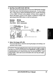
INSTALLATION (Jumpers) 4. You must enter BIOS to the two pins. ASUS P/I-P65UP8 User's Manual 15 Real Time Clock (RTC) RAM (RTCLR) This clears the user-entered information stored in the CMOS RAM of the Real Time Clock ...
INSTALLATION (Jumpers) 4. You must enter BIOS to the two pins. ASUS P/I-P65UP8 User's Manual 15 Real Time Clock (RTC) RAM (RTCLR) This clears the user-entered information stored in the CMOS RAM of the Real Time Clock ...
User Manual
Page 16
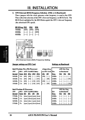
... 4.5x [open] [short] [open] [short] 266MHz 4.0x [short] [short [open] [short] 233MHz 35x [open] [open] [short] [short] Ext. Freq on Baseboard) FS2 FS1 FS0 16 ASUS P/I-P65UP8 User's Manual CPU External (BUS) Frequency Selection (FS0, 1, 2) (Baseboard) These jumpers tells the clock generator what frequency to send to the CPU. FS2 FS1 FS0...
... 4.5x [open] [short] [open] [short] 266MHz 4.0x [short] [short [open] [short] 233MHz 35x [open] [open] [short] [short] Ext. Freq on Baseboard) FS2 FS1 FS0 16 ASUS P/I-P65UP8 User's Manual CPU External (BUS) Frequency Selection (FS0, 1, 2) (Baseboard) These jumpers tells the clock generator what frequency to send to the CPU. FS2 FS1 FS0...
User Manual
Page 17
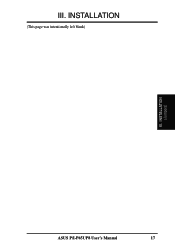
INSTALLATION (Jumpers) ASUS P/I-P65UP8 User's Manual 17 III. INSTALLATION (This page was intentionally left blank) III.
INSTALLATION (Jumpers) ASUS P/I-P65UP8 User's Manual 17 III. INSTALLATION (This page was intentionally left blank) III.

User Manual
Page 18
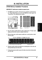
... SIMM (e.g. 8 chips + 4 parity chips) in pairs so that each bank contains two of the BIOS software. The i960 does not support parity or ECC. 18 ASUS P/I-P65UP8 User's Manual
... SIMM (e.g. 8 chips + 4 parity chips) in pairs so that each bank contains two of the BIOS software. The i960 does not support parity or ECC. 18 ASUS P/I-P65UP8 User's Manual
User Manual
Page 19
... mounting holes on the sides and the clips should snap on one end of the SIMM slots which requires the "Notched End" of the clips. ASUS P/I-P65UP8 User's Manual 19 To release the memory module, squeeze both clips outward and rock the module out of the SIMM memory modules. Clip 72 Pin...
... mounting holes on the sides and the clips should snap on one end of the SIMM slots which requires the "Notched End" of the clips. ASUS P/I-P65UP8 User's Manual 19 To release the memory module, squeeze both clips outward and rock the module out of the SIMM memory modules. Clip 72 Pin...
User Manual
Page 20
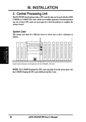
INSTALLATION 3. Central Processing Unit The P/I -P65UP8 User's Manual INSTALLATION (CPU Card) 20 ASUS P/I -P65UP8 baseboard provides a CPU card slot that can easily fit in the given space, but the C-PKND Pentium II CPU card will block the ISA 3 ...2 3/4" (7.0 cm) Pentium II Processor Pentium II Heatsink 2 1/2" (6.4 cm) 12.2" (30.7 cm) System Cabinet Clearance Area Requirement for the P/I-P65UP8 + CPU Card NOTE: The C-P6ND Pentium Pro CPU card can be used with the ASUS C-PKND or C-P6ND CPU cards, which are available separately. III. Secondary PCI 4 Long Card 5" (12.7 cm) Secondary PCI...
INSTALLATION 3. Central Processing Unit The P/I -P65UP8 User's Manual INSTALLATION (CPU Card) 20 ASUS P/I -P65UP8 baseboard provides a CPU card slot that can easily fit in the given space, but the C-PKND Pentium II CPU card will block the ISA 3 ...2 3/4" (7.0 cm) Pentium II Processor Pentium II Heatsink 2 1/2" (6.4 cm) 12.2" (30.7 cm) System Cabinet Clearance Area Requirement for the P/I-P65UP8 + CPU Card NOTE: The C-P6ND Pentium Pro CPU card can be used with the ASUS C-PKND or C-P6ND CPU cards, which are available separately. III. Secondary PCI 4 Long Card 5" (12.7 cm) Secondary PCI...
User Manual
Page 21
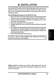
...the CPU card is available for the first slot. 4. Screw in . WARNING! III. Refer to your respective CPU card's documentation for the ASUS CPU Card: 1. General Installation Procedures for details. Remove the expansion slot cover for the bracket. Carefully align the CPU card over the CPU Card...bracket, which should slide into the slots. 6. Be sure that came with the CPU card and replace it onto the antistatic bag. 2. III. ASUS P/I-P65UP8 User's Manual 21 Firmly press one is perpendicular to the system case. When adding a CPU card, find the BIOS chip that the card is...
...the CPU card is available for the first slot. 4. Screw in . WARNING! III. Refer to your respective CPU card's documentation for the ASUS CPU Card: 1. General Installation Procedures for details. Remove the expansion slot cover for the bracket. Carefully align the CPU card over the CPU Card...bracket, which should slide into the slots. 6. Be sure that came with the CPU card and replace it onto the antistatic bag. 2. III. ASUS P/I-P65UP8 User's Manual 21 Firmly press one is perpendicular to the system case. When adding a CPU card, find the BIOS chip that the card is...


