
P5S-B User Manual
Page 1
R P5S-B Super7 Baby AT Motherboard USER'S MANUAL
R P5S-B Super7 Baby AT Motherboard USER'S MANUAL
P5S-B User Manual
Page 4
HARDWARE SETUP 12 ASUS P5S-B Motherboard Layout 12 Hardware Setup Steps 15 1. Expansion Cards 29 Expansion Card Installation Procedure 29 Assigning IRQs for Expansion Cards 29 Assigning DMA Channels ...54 Power Management Setup 57 Details of Power Management Setup 57 PNP and PCI Setup 60 Details of the ASUS P5S-B Motherboard 11 III. FEATURES 8 ASUS P5S-B Motherboard 8 Parts of PNP and PCI Setup 60 4 ASUS P5S-B User's Manual Motherboard Settings 15 Compatible Cyrix CPU Identification 23 2. External Connectors 31 Power Connection Procedures 43 Flash Memory Writer ...
HARDWARE SETUP 12 ASUS P5S-B Motherboard Layout 12 Hardware Setup Steps 15 1. Expansion Cards 29 Expansion Card Installation Procedure 29 Assigning IRQs for Expansion Cards 29 Assigning DMA Channels ...54 Power Management Setup 57 Details of Power Management Setup 57 PNP and PCI Setup 60 Details of the ASUS P5S-B Motherboard 11 III. FEATURES 8 ASUS P5S-B Motherboard 8 Parts of PNP and PCI Setup 60 4 ASUS P5S-B User's Manual Motherboard Settings 15 Compatible Cyrix CPU Identification 23 2. External Connectors 31 Power Connection Procedures 43 Flash Memory Writer ...
P5S-B User Manual
Page 7
Introduction II. Installation IV. If you discover damaged or missing items, contact your retailer. (1) ASUS Motherboard (1) Ribbon cable for master and slave IDE drives (1) Ribbon cable for (1) 5.25" and (2) 3.5" floppy disk drives (1) Ribbon cable... Instructions on motherboard/jumper setup Instructions on BIOS software setup Information on the included support software References for audio input/output and game/MIDI port (with audio chip onboard) ASUS IrDA-compliant module (optional) ASUS PCI-L101 Wake-On-LAN 10/100 ethernet card (optional) ASUS P5S-B User's Manual 7 Software...
Introduction II. Installation IV. If you discover damaged or missing items, contact your retailer. (1) ASUS Motherboard (1) Ribbon cable for master and slave IDE drives (1) Ribbon cable for (1) 5.25" and (2) 3.5" floppy disk drives (1) Ribbon cable... Instructions on motherboard/jumper setup Instructions on BIOS software setup Information on the included support software References for audio input/output and game/MIDI port (with audio chip onboard) ASUS IrDA-compliant module (optional) ASUS PCI-L101 Wake-On-LAN 10/100 ethernet card (optional) ASUS P5S-B User's Manual 7 Software...
P5S-B User Manual
Page 8
...ASUS P5S-B Motherboard The ASUS P5S-B is available) pipelined-burst SRAM/ L2 memory cache and integrated Tag RAM to make using the 100MHz bus speed possible. • PC100 Memory Support: Equipped with SIR) to the Infrared Module for wireless connections. • USB: Supports the Universal Serial Bus standard through an optional ASUS... connecting a digital flat panel to 768MB. FEATURES Features II. UART2 can also be directed from ASUS. • UltraDMA/66 BM IDE: Comes with an onboard PCI Bus Master IDE controller with ..., 128, or 256MB) up to your PC. 8 ASUS P5S-B User's Manual
...ASUS P5S-B Motherboard The ASUS P5S-B is available) pipelined-burst SRAM/ L2 memory cache and integrated Tag RAM to make using the 100MHz bus speed possible. • PC100 Memory Support: Equipped with SIR) to the Infrared Module for wireless connections. • USB: Supports the Universal Serial Bus standard through an optional ASUS... connecting a digital flat panel to 768MB. FEATURES Features II. UART2 can also be directed from ASUS. • UltraDMA/66 BM IDE: Comes with an onboard PCI Bus Master IDE controller with ..., 128, or 256MB) up to your PC. 8 ASUS P5S-B User's Manual
P5S-B User Manual
Page 9
... for virtually automatic setup. • Desktop Management Interface (DMI): Supports DMI through Trend ChipAway Virus codes, and autodetection of this motherboard meet PC'98 compliancy. UltraDMA/66 is backward compatible with both DMA/33 and DMA and with its chipset and support for its... Compliant: Both the BIOS and hardware levels of most devices for RPM and failure. ASUS P5S-B User's Manual 9 ter busses to the memory and processor. • High-Speed Data Transfer Interface: This motherboard with existing DMA devices and systems so there is no need to upgrade current EIDE/...
... for virtually automatic setup. • Desktop Management Interface (DMI): Supports DMI through Trend ChipAway Virus codes, and autodetection of this motherboard meet PC'98 compliancy. UltraDMA/66 is backward compatible with both DMA/33 and DMA and with its chipset and support for its... Compliant: Both the BIOS and hardware levels of most devices for RPM and failure. ASUS P5S-B User's Manual 9 ter busses to the memory and processor. • High-Speed Data Transfer Interface: This motherboard with existing DMA devices and systems so there is no need to upgrade current EIDE/...
P5S-B User Manual
Page 10
... when temperature falls below a safe level. • Remote Ring On (requires external modem): This feature allows a computer to critical motherboard components. This function reduces both energy consumption and system noise, and is an important feature in implementing silent PC systems. •...by pressing the keyboard's spacebar. • Voltage Monitoring and Alert: System voltage levels are used up to the user. 10 ASUS P5S-B User's Manual A simple glimpse provides useful information to prevent possible application crashes. The system resource monitor will deactivate the CPU ...
... when temperature falls below a safe level. • Remote Ring On (requires external modem): This feature allows a computer to critical motherboard components. This function reduces both energy consumption and system noise, and is an important feature in implementing silent PC systems. •...by pressing the keyboard's spacebar. • Voltage Monitoring and Alert: System voltage levels are used up to the user. 10 ASUS P5S-B User's Manual A simple glimpse provides useful information to prevent possible application crashes. The system resource monitor will deactivate the CPU ...
P5S-B User Manual
Page 11
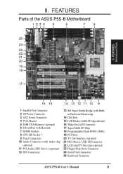
... II. FEATURES Parts of the ASUS P5S-B Motherboard 1234 5 6 7 8 25 24 23 22 21 20 19 18 17 16 15 14 13 12 11 10 9 1 Parallel Port Connector 2 AT Power Connector 3 ATX Power ...) 21 PS/2 Mouse, USB, IR Connector 22 LCD chip/TV Out chip (optional) 23 Floppy Disk Drive Connector 24 Serial Port Connectors 25 Keyboard Connector ASUS P5S-B User's Manual 11 II.
... II. FEATURES Parts of the ASUS P5S-B Motherboard 1234 5 6 7 8 25 24 23 22 21 20 19 18 17 16 15 14 13 12 11 10 9 1 Parallel Port Connector 2 AT Power Connector 3 ATX Power ...) 21 PS/2 Mouse, USB, IR Connector 22 LCD chip/TV Out chip (optional) 23 Floppy Disk Drive Connector 24 Serial Port Connectors 25 Keyboard Connector ASUS P5S-B User's Manual 11 II.
P5S-B User Manual
Page 12
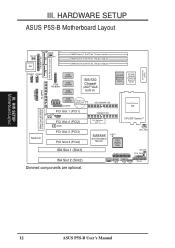
... ZIF Socket 7 CPU_FAN SiS5595 with Hardware Monitor CLRTC ESS Audio Chip MODEM Audio Connectors AUX CD1 CD2 IDELED CHA_FAN IR Panel 12 ASUS P5S-B User's Manual 01 III. HARDWARE SETUP ASUS P5S-B Motherboard Layout ATX Power Connector Parallel Port KB_UP KB PS/2PWR Row 0 PWR_FAN 1 2 P8 3 4 5 DIMM Socket 1 (64/72-bit, 168-pin module) DIMM... 1 (PCI1) WOL_CON SMB PCI Slot 2 (PCI2) WOR PCI Slot 3 (PCI3) Multi I/O PCI Slot 4 (PCI4) ISA Slot 1 (Slot1) ISA Slot 2 (Slot2) Dimmed components are optional. H/W SETUP Motherboard Layout III.
... ZIF Socket 7 CPU_FAN SiS5595 with Hardware Monitor CLRTC ESS Audio Chip MODEM Audio Connectors AUX CD1 CD2 IDELED CHA_FAN IR Panel 12 ASUS P5S-B User's Manual 01 III. HARDWARE SETUP ASUS P5S-B Motherboard Layout ATX Power Connector Parallel Port KB_UP KB PS/2PWR Row 0 PWR_FAN 1 2 P8 3 4 5 DIMM Socket 1 (64/72-bit, 168-pin module) DIMM... 1 (PCI1) WOL_CON SMB PCI Slot 2 (PCI2) WOR PCI Slot 3 (PCI3) Multi I/O PCI Slot 4 (PCI4) ISA Slot 1 (Slot1) ISA Slot 2 (Slot2) Dimmed components are optional. H/W SETUP Motherboard Layout III.

P5S-B User Manual
Page 13
...Switches 4, 5 p. 18 VIO Setting 6) DIP 2 - Switch 10 p. 19 LCD Setting (Enable/Disable) 8) DIP 2 - H/W SETUP Contents III. HARDWARE SETUP Motherboard Feature Settings 1) KB_UP p. 16 Keyboard Power (Wake) Up (Enable/Disable) 2) DIP 1 - Switches 6, 7, 8, 9, 10 p. 23 Voltage Regulator Output Selection ...(2 pins) p. 37 Keyboard Lock Switch Lead (2 pins) p. 37 Speaker Output Connector (4 pins) p. 38 Wake-On-LAN Activity Connector (3 pins) ASUS P5S-B User's Manual 13 III. Switch 9 p. 19 TV Out Setting (AV/RGB) 7) DIP 2 - Switch 5 p. 20 Memory Transfer Mode Setting 10...
...Switches 4, 5 p. 18 VIO Setting 6) DIP 2 - Switch 10 p. 19 LCD Setting (Enable/Disable) 8) DIP 2 - H/W SETUP Contents III. HARDWARE SETUP Motherboard Feature Settings 1) KB_UP p. 16 Keyboard Power (Wake) Up (Enable/Disable) 2) DIP 1 - Switches 6, 7, 8, 9, 10 p. 23 Voltage Regulator Output Selection ...(2 pins) p. 37 Keyboard Lock Switch Lead (2 pins) p. 37 Speaker Output Connector (4 pins) p. 38 Wake-On-LAN Activity Connector (3 pins) ASUS P5S-B User's Manual 13 III. Switch 9 p. 19 TV Out Setting (AV/RGB) 7) DIP 2 - Switch 5 p. 20 Memory Transfer Mode Setting 10...
P5S-B User Manual
Page 15
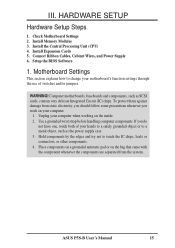
... electricity, you should follow some precautions whenever you do not have one, touch both of switches and/or jumpers. Computer motherboards, baseboards and components, such as the power supply case. 3. Hold components by the edges and try not to change ... working on the inside. 2. To protect them against damage from the system. ASUS P5S-B User's Manual 15 Install Memory Modules 3. Install Expansion Cards 5. WARNING! Connect Ribbon Cables, Cabinet Wires, and Power Supply 6. Unplug your motherboard's function settings through the use of your computer. 1.
... electricity, you should follow some precautions whenever you do not have one, touch both of switches and/or jumpers. Computer motherboards, baseboards and components, such as the power supply case. 3. Hold components by the edges and try not to change ... working on the inside. 2. To protect them against damage from the system. ASUS P5S-B User's Manual 15 Install Memory Modules 3. Install Expansion Cards 5. WARNING! Connect Ribbon Cables, Cabinet Wires, and Power Supply 6. Unplug your motherboard's function settings through the use of your computer. 1.
P5S-B User Manual
Page 16
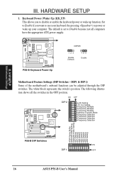
... block represents the switch's position. The default is set to power or wake up function. DIP1 & DIP 2) Some of the motherboard's onboard functions can be adjusted through the DIP switches. The following illustration shows all computers have the appropriate ATX power supply. ON OFF... DIP 2 ON 1 2 3 4 5 6 7 8 9 10 P5S-B Keyboard Power Up KBPWR 123 Disable (Default) 123 Enable Motherboard Feature Settings (DIP Switches - H/W SETUP Motherboard Settings III. 01 01 III. Keyboard Power (Wake) Up (KB_UP) This allows you want to use your ...
... block represents the switch's position. The default is set to power or wake up function. DIP1 & DIP 2) Some of the motherboard's onboard functions can be adjusted through the DIP switches. The following illustration shows all computers have the appropriate ATX power supply. ON OFF... DIP 2 ON 1 2 3 4 5 6 7 8 9 10 P5S-B Keyboard Power Up KBPWR 123 Disable (Default) 123 Enable Motherboard Feature Settings (DIP Switches - H/W SETUP Motherboard Settings III. 01 01 III. Keyboard Power (Wake) Up (KB_UP) This allows you want to use your ...
P5S-B User Manual
Page 17
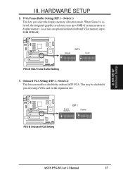
... is selected, the integrated graphics accelerator uses up to 8MB of system memory as display memory. VGA Frame Buffer Setting (DIP 1 - H/W SETUP Motherboard Settings III. Local uses an optional dedicated onboard VGA memory (up to 8MB SDRAM). 01 Shared ON DIP 1 ON Local 1 2 3 4 5 6 7 8 9 10... on the expansion slot. 01 Enable (Default) ON DIP 1 Disable ON 1 2 3 4 5 6 7 8 9 10 1 2 3 4 5 6 7 8 9 10 P5S-B Onboard VGA Setting ASUS P5S-B User's Manual 17 This may be disabled if you enable or disable the onboard AGP VGA. Switch 1) This lets you select the display memory...
... is selected, the integrated graphics accelerator uses up to 8MB of system memory as display memory. VGA Frame Buffer Setting (DIP 1 - H/W SETUP Motherboard Settings III. Local uses an optional dedicated onboard VGA memory (up to 8MB SDRAM). 01 Shared ON DIP 1 ON Local 1 2 3 4 5 6 7 8 9 10... on the expansion slot. 01 Enable (Default) ON DIP 1 Disable ON 1 2 3 4 5 6 7 8 9 10 1 2 3 4 5 6 7 8 9 10 P5S-B Onboard VGA Setting ASUS P5S-B User's Manual 17 This may be disabled if you enable or disable the onboard AGP VGA. Switch 1) This lets you select the display memory...
P5S-B User Manual
Page 18
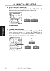
.... Setting this function switch to the DRAM, chipset, AGP, and the CPU's I /O Setting DIP 1 3.5Volt (Default) ON 1 2 3 4 5 6 7 8 9 10 3.6Volt ON 1 2 3 4 5 6 7 8 9 10 3.8Volt ON 1 2 3 4 5 6 7 8 9 10 18 ASUS P5S-B User's Manual 01 01 III. Onboard Audio Setting (DIP 1-Switch 3) This lets you leave your switch on the expansion slot. This should be disabled if... on its default setting of 3.5V. HARDWARE SETUP 4. It is strongly recommended that you enable or disable the optional onboard 32-bit PCI audio. H/W SETUP Motherboard Settings III.
.... Setting this function switch to the DRAM, chipset, AGP, and the CPU's I /O Setting DIP 1 3.5Volt (Default) ON 1 2 3 4 5 6 7 8 9 10 3.6Volt ON 1 2 3 4 5 6 7 8 9 10 3.8Volt ON 1 2 3 4 5 6 7 8 9 10 18 ASUS P5S-B User's Manual 01 01 III. Onboard Audio Setting (DIP 1-Switch 3) This lets you leave your switch on the expansion slot. This should be disabled if... on its default setting of 3.5V. HARDWARE SETUP 4. It is strongly recommended that you enable or disable the optional onboard 32-bit PCI audio. H/W SETUP Motherboard Settings III.
P5S-B User Manual
Page 19
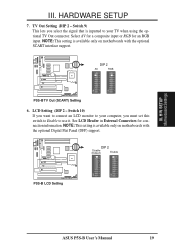
... using the optional TV Out connector. NOTE: This setting is available only on motherboards with the optional SCART interface support. 01 DIP 2 AV RGB ON 1 2 3 4 5 6 7 8 9 10 ON 1 2 3 4 5 6 7 8 9 10 P5S-B TV Out (SCART) Setting 6. HARDWARE SETUP 7. Switch 10) If you ...inputted to use it. H/W SETUP Motherboard Settings III. NOTE: This setting is available only on motherboards with the optional Digital Flat Panel (DFP) support. 01 DIP 2 Disable (Default) Enable ON 1 2 3 4 5 6 7 8 9 10 ON 1 2 3 4 5 6 7 8 9 10 P5S-B LCD Setting ASUS P5S-B User's Manual 19 See LCD Header...
... using the optional TV Out connector. NOTE: This setting is available only on motherboards with the optional SCART interface support. 01 DIP 2 AV RGB ON 1 2 3 4 5 6 7 8 9 10 ON 1 2 3 4 5 6 7 8 9 10 P5S-B TV Out (SCART) Setting 6. HARDWARE SETUP 7. Switch 10) If you ...inputted to use it. H/W SETUP Motherboard Settings III. NOTE: This setting is available only on motherboards with the optional Digital Flat Panel (DFP) support. 01 DIP 2 Disable (Default) Enable ON 1 2 3 4 5 6 7 8 9 10 ON 1 2 3 4 5 6 7 8 9 10 P5S-B LCD Setting ASUS P5S-B User's Manual 19 See LCD Header...
P5S-B User Manual
Page 20
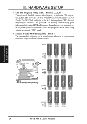
...speed independently from the CPU Bus Frequency. HARDWARE SETUP 8. CPU BUS Frequency Setting (DIP 2 - H/W SETUP Motherboard Settings III. Depending on your memory type, PC66 (66MHz) ot PC100 (100MHz), select the appropriate "RAM"...ON 1 2 3 4 5 6 7 8 9 10 ON 1 2 3 4 5 6 7 8 9 10 ON 1 2 3 4 5 6 7 8 9 10 ON 1 2 3 4 5 6 7 8 9 10 (SYNC) CPU SDRAM PCI 100MHz 100MHz 33MHz 105MHz 105MHz 35MHz 112MHz 112MHz 37MHz P5S-B CPU Bus Frequency Setting (ASYNC) CPU SDRAM PCI 66MHz 100MHz 33MHz 75MHz 100MHz 37MHz 90MHz 60MHz 30MHz 95MHz 63MHz 32MHz ON 1 2 3 4 5 6 7 8 9 10 ON 1 2 3 4 5 6 7 8 9 10 ON...
...speed independently from the CPU Bus Frequency. HARDWARE SETUP 8. CPU BUS Frequency Setting (DIP 2 - H/W SETUP Motherboard Settings III. Depending on your memory type, PC66 (66MHz) ot PC100 (100MHz), select the appropriate "RAM"...ON 1 2 3 4 5 6 7 8 9 10 ON 1 2 3 4 5 6 7 8 9 10 ON 1 2 3 4 5 6 7 8 9 10 ON 1 2 3 4 5 6 7 8 9 10 (SYNC) CPU SDRAM PCI 100MHz 100MHz 33MHz 105MHz 105MHz 35MHz 112MHz 112MHz 37MHz P5S-B CPU Bus Frequency Setting (ASYNC) CPU SDRAM PCI 66MHz 100MHz 33MHz 75MHz 100MHz 37MHz 90MHz 60MHz 30MHz 95MHz 63MHz 32MHz ON 1 2 3 4 5 6 7 8 9 10 ON 1 2 3 4 5 6 7 8 9 10 ON...
P5S-B User Manual
Page 21
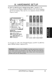
... B → - - - - Frequencies above 100MHz exceed the specifications for the onboard chipset and are not guaranteed to the instructions included with the CPU BUS Frequency Setting. ASUS P5S-B User's Manual 21 CPU Core:BUS Frequency Multiple Setting (DIP 2 - WARNING! CPU E → 4.0x(4/1) 4.5x(9/2) 2.33x(7/3) 2.66x(8/3) CPU F → 4.0x(4/1) 4.0x...2.0x(2/1) 2.5x(5/2) 3.0x(3/1) CPU B →1.5x(3/2) 2.0x(2/1) 2.5x(5/2) 3.0x(3/1) CPU C →3.5x(7/2) 2.0x(2/1) 2.5x(5/2) 3.0x(3/1) CPU D → 3.0x(3/1) 2.0x(2/1) 1.0x(1/1) - H/W SETUP Motherboard Settings III.
... B → - - - - Frequencies above 100MHz exceed the specifications for the onboard chipset and are not guaranteed to the instructions included with the CPU BUS Frequency Setting. ASUS P5S-B User's Manual 21 CPU Core:BUS Frequency Multiple Setting (DIP 2 - WARNING! CPU E → 4.0x(4/1) 4.5x(9/2) 2.33x(7/3) 2.66x(8/3) CPU F → 4.0x(4/1) 4.0x...2.0x(2/1) 2.5x(5/2) 3.0x(3/1) CPU B →1.5x(3/2) 2.0x(2/1) 2.5x(5/2) 3.0x(3/1) CPU C →3.5x(7/2) 2.0x(2/1) 2.5x(5/2) 3.0x(3/1) CPU D → 3.0x(3/1) 2.0x(2/1) 1.0x(1/1) - H/W SETUP Motherboard Settings III.
P5S-B User Manual
Page 22
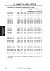
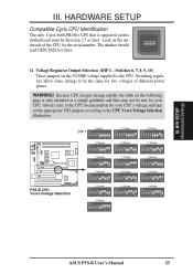
... 6x86L-PR166+* 133MHz D-2.0x 66MHz [ON] [ON] [ON] [ON] [ON] [OFF] [OFF] *The only IBM or Cyrix 6x86(L) (or M1) that is supported on this motherboard is revision 2.7 or later (see next page). 22 ASUS P5S-B User's Manual H/W SETUP Motherboard Settings III. III.
... 6x86L-PR166+* 133MHz D-2.0x 66MHz [ON] [ON] [ON] [ON] [ON] [OFF] [OFF] *The only IBM or Cyrix 6x86(L) (or M1) that is supported on this motherboard is revision 2.7 or later (see next page). 22 ASUS P5S-B User's Manual H/W SETUP Motherboard Settings III. III.
P5S-B User Manual
Page 23
...is supported on the underside of different power planes. The number should read G8DC6620A or later. 11. H/W SETUP Motherboard Settings III. Look on this motherboard must be the same for two voltages of the CPU for the serial number. Always refer to the CPU ...7 8 9 10 2.9Volts ON 1 2 3 4 5 6 7 8 9 10 3.0Volts ON 1 2 3 4 5 6 7 8 9 10 3.1Volts ON 1 2 3 4 5 6 7 8 9 10 3.2Volts ON 1 2 3 4 5 6 7 8 9 10 3.3Volts ON 1 2 3 4 5 6 7 8 9 10 3.4Volts ON 1 2 3 4 5 6 7 8 9 10 3.5Volts ON 1 2 3 4 5 6 7 8 9 10 1 2 3 4 5 6 7 8 9 10 1 2 3 4 5 6 7 8 9 10 ASUS P5S-B User's Manual 23
...is supported on the underside of different power planes. The number should read G8DC6620A or later. 11. H/W SETUP Motherboard Settings III. Look on this motherboard must be the same for two voltages of the CPU for the serial number. Always refer to the CPU ...7 8 9 10 2.9Volts ON 1 2 3 4 5 6 7 8 9 10 3.0Volts ON 1 2 3 4 5 6 7 8 9 10 3.1Volts ON 1 2 3 4 5 6 7 8 9 10 3.2Volts ON 1 2 3 4 5 6 7 8 9 10 3.3Volts ON 1 2 3 4 5 6 7 8 9 10 3.4Volts ON 1 2 3 4 5 6 7 8 9 10 3.5Volts ON 1 2 3 4 5 6 7 8 9 10 1 2 3 4 5 6 7 8 9 10 1 2 3 4 5 6 7 8 9 10 ASUS P5S-B User's Manual 23
P5S-B User Manual
Page 24
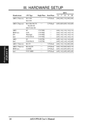
III. P55C-MMX ---- H/W SETUP Motherboard Settings 24 ASUS P5S-B User's Manual K6-2/450 K6-2/266,300,333, ---366,380,400 K6/233,266,300 K5 6x86 WinChip2 P54C/P54CS 3.5V(VRE) 3.5V(VRE) 3.5V(...
III. P55C-MMX ---- H/W SETUP Motherboard Settings 24 ASUS P5S-B User's Manual K6-2/450 K6-2/266,300,333, ---366,380,400 K6/233,266,300 K5 6x86 WinChip2 P54C/P54CS 3.5V(VRE) 3.5V(VRE) 3.5V(...
P5S-B User Manual
Page 25
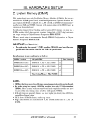
...higher pin density than EDO (Extended Data Output) chips. • BIOS shows SDRAM memory on the motherboard. To utilize the chipset's Error Checking and Correction (ECC) feature, you must be com- patible with...• SDRAM chips are available in Chipset Features Setup under BIOS SETUP. System Memory (DIMM) This motherboard uses only Dual Inline Memory Modules (DIMMs). Install memory in 32, 64, 128, 256MB. IMPORTANT!...have more than 18 chips are not supported on this motherboard. • To make using bus speeds ≥95MHz possible, use a DIMM module with the current...
...higher pin density than EDO (Extended Data Output) chips. • BIOS shows SDRAM memory on the motherboard. To utilize the chipset's Error Checking and Correction (ECC) feature, you must be com- patible with...• SDRAM chips are available in Chipset Features Setup under BIOS SETUP. System Memory (DIMM) This motherboard uses only Dual Inline Memory Modules (DIMMs). Install memory in 32, 64, 128, 256MB. IMPORTANT!...have more than 18 chips are not supported on this motherboard. • To make using bus speeds ≥95MHz possible, use a DIMM module with the current...


