
Motherboard Installation Guide
Page 1
P5RD1-V Motherboard
P5RD1-V Motherboard

Motherboard Installation Guide
Page 3
... to find more information ix Conventions used in this guide x Typography x P5RD1-V specifications summary xi Chapter 1: Product introduction 1.1 Welcome 1-1 1.2 Package contents 1-1 1.3 Special features 1-2 1.3.1 Product highlights 1-2 1.3.2 ASUS Proactive features 1-4 1.3.3 Innovative ASUS features 1-5 Chapter 2: Hardware information 2.1 Before you proceed 2-1 2.2 Motherboard overview 2-2 2.2.1 Placement direction 2-2 2.2.2 Screw holes 2-2 2.2.3 Motherboard layout 2-3 2.2.4 Layout Contents 2-4 2.3 Central Processing Unit (CPU 2-6 2.3.1 Installing the CPU 2-6 2.3.2 Installing...
... to find more information ix Conventions used in this guide x Typography x P5RD1-V specifications summary xi Chapter 1: Product introduction 1.1 Welcome 1-1 1.2 Package contents 1-1 1.3 Special features 1-2 1.3.1 Product highlights 1-2 1.3.2 ASUS Proactive features 1-4 1.3.3 Innovative ASUS features 1-5 Chapter 2: Hardware information 2.1 Before you proceed 2-1 2.2 Motherboard overview 2-2 2.2.1 Placement direction 2-2 2.2.2 Screw holes 2-2 2.2.3 Motherboard layout 2-3 2.2.4 Layout Contents 2-4 2.3 Central Processing Unit (CPU 2-6 2.3.1 Installing the CPU 2-6 2.3.2 Installing...

Motherboard Installation Guide
Page 8
... the product, make sure all cables are correctly connected and the power cables are not damaged. Operation safety • Before installing the motherboard and adding devices on a stable surface. • If you encounter technical problems with the package. • Before using an adapter or...in any damage, contact your dealer immediately. • To avoid short circuits, keep paper clips, screws, and staples away from the motherboard, ensure that came with the product, contact a qualified service technician or your retailer. These devices could interrupt the grounding circuit. •...
... the product, make sure all cables are correctly connected and the power cables are not damaged. Operation safety • Before installing the motherboard and adding devices on a stable surface. • If you encounter technical problems with the package. • Before using an adapter or...in any damage, contact your dealer immediately. • To avoid short circuits, keep paper clips, screws, and staples away from the motherboard, ensure that came with the product, contact a qualified service technician or your retailer. These devices could interrupt the grounding circuit. •...

Motherboard Installation Guide
Page 9
...through the BIOS Setup menus. ASUS websites The ASUS website provides updated information on the motherboard. • Chapter 3: Powering up This chapter describes the power up sequence, the vocal POST messages, and ways of the switches, jumpers, and connectors on ASUS hardware and software products. These... such as warranty flyers, that comes with the motherboard package. Refer to perform when installing system components. Detailed descriptions of the BIOS parameters are not part of the support CD that may have to the ASUS contact information. 2. How this guide This user ...
...through the BIOS Setup menus. ASUS websites The ASUS website provides updated information on the motherboard. • Chapter 3: Powering up This chapter describes the power up sequence, the vocal POST messages, and ways of the switches, jumpers, and connectors on ASUS hardware and software products. These... such as warranty flyers, that comes with the motherboard package. Refer to perform when installing system components. Detailed descriptions of the BIOS parameters are not part of the support CD that may have to the ASUS contact information. 2. How this guide This user ...

Motherboard Installation Guide
Page 13
This chapter describes the motherboard features and the new technologies it supports. 1Product introduction
This chapter describes the motherboard features and the new technologies it supports. 1Product introduction
Motherboard Installation Guide
Page 15
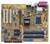
... items. Motherboard ASUS P5RD1-V motherboard I/O modules Serial port module (COM port) USB 2.0 (2 ports) and GAME (1 port) module Cables 2 x Serial ATA signal cables 1 x Serial ATA power cables (dual plugs) 1 x Ultra DMA/133 cables 40-conductor IDE cable Floppy disk drive cable Accessories I/O shield A p p l i c a t i o n C D s ASUS motherboard support CD D o c u m e n t a t i o n User guide If any of ASUS quality motherboards! 1.1 Welcome! ASUS P5RD1-V 1-1 The motherboard delivers a host...
... items. Motherboard ASUS P5RD1-V motherboard I/O modules Serial port module (COM port) USB 2.0 (2 ports) and GAME (1 port) module Cables 2 x Serial ATA signal cables 1 x Serial ATA power cables (dual plugs) 1 x Ultra DMA/133 cables 40-conductor IDE cable Floppy disk drive cable Accessories I/O shield A p p l i c a t i o n C D s ASUS motherboard support CD D o c u m e n t a t i o n User guide If any of ASUS quality motherboards! 1.1 Welcome! ASUS P5RD1-V 1-1 The motherboard delivers a host...

Motherboard Installation Guide
Page 16
...the ULI M1573 Southbridge provide the vital interfaces for enhanced 3D, 2D, and video capabilities. Serial ATA technology The motherboard supports the Serial ATA technology through the Serial ATA interfaces and the ULI® M1573. 1.3 Special features 1.3.1 Product highlights .... The ATI RADEON® XPRESS 200 Northbridge integrates the RADEON® X300, an integrated graphics processing unit (GPU) for the motherboard. Enhanced Intel SpeedStep® Technology (EIST) The Enhanced Intel SpeedStep® Technology (EIST) intelligently manages the CPU resources by automatically...
...the ULI M1573 Southbridge provide the vital interfaces for enhanced 3D, 2D, and video capabilities. Serial ATA technology The motherboard supports the Serial ATA technology through the Serial ATA interfaces and the ULI® M1573. 1.3 Special features 1.3.1 Product highlights .... The ATI RADEON® XPRESS 200 Northbridge integrates the RADEON® X300, an integrated graphics processing unit (GPU) for the motherboard. Enhanced Intel SpeedStep® Technology (EIST) The Enhanced Intel SpeedStep® Technology (EIST) intelligently manages the CPU resources by automatically...

Motherboard Installation Guide
Page 17
... ports, and S/PDIF interfaces, you can connect your computer to home theater decoders to ensure stable supply of current for timely failure detection. ASUS P5RD1-V 1-3 PCI Express™ interface The motherboard fully supports PCI Express, the latest I /O) to -point serial interconnections between devices and allows higher clockspeeds by the ASIC (integrated in packets...
... ports, and S/PDIF interfaces, you can connect your computer to home theater decoders to ensure stable supply of current for timely failure detection. ASUS P5RD1-V 1-3 PCI Express™ interface The motherboard fully supports PCI Express, the latest I /O) to -point serial interconnections between devices and allows higher clockspeeds by the ASIC (integrated in packets...

Motherboard Installation Guide
Page 18
... shorts and faults up to buy a replacement ROM chip. See page 4-32 for details. 1.3.3 Innovative ASUS features CrashFree BIOS 2 This feature allows you to restore the original BIOS data from the support CD in the motherboard allows you can easily monitor the condition of the Ethernet cable(s) connected to ensure quiet, cool...
... shorts and faults up to buy a replacement ROM chip. See page 4-32 for details. 1.3.3 Innovative ASUS features CrashFree BIOS 2 This feature allows you to restore the original BIOS data from the support CD in the motherboard allows you can easily monitor the condition of the Ethernet cable(s) connected to ensure quiet, cool...

Motherboard Installation Guide
Page 19
This chapter lists the hardware setup procedures that you have to perform when installing system components. It includes description of the jumpers and connectors on the motherboard. 2 Hardware information
This chapter lists the hardware setup procedures that you have to perform when installing system components. It includes description of the jumpers and connectors on the motherboard. 2 Hardware information

Motherboard Installation Guide
Page 20
Chapter summary 2.1 Before you proceed 2-1 2.2 Motherboard overview 2-2 2.3 Central Processing Unit (CPU 2-6 2.4 System memory 2-13 2.5 Expansion slots 2-17 2.6 Jumpers 2-20 2.7 Connectors 2-23 ASUS P5RD1-V
Chapter summary 2.1 Before you proceed 2-1 2.2 Motherboard overview 2-2 2.3 Central Processing Unit (CPU 2-6 2.4 System memory 2-13 2.5 Expansion slots 2-17 2.6 Jumpers 2-20 2.7 Connectors 2-23 ASUS P5RD1-V

Motherboard Installation Guide
Page 21
...touch a safely grounded object or to a metal object, such as the power supply case, before removing or plugging in any motherboard component. Onboard LED The motherboard comes with the component. • Before you install or remove any component, place it on a grounded antistatic pad or ...in the bag that came with a standby power LED that lights up to the motherboard, peripherals, and/or components. P5RD1-V ® SB_PWR P5RD1-V Onboard LED ON Standby Power OFF Powered Off ASUS P5RD1-V 2-1 This is switched off mode. Failure to do so may cause severe damage to ...
...touch a safely grounded object or to a metal object, such as the power supply case, before removing or plugging in any motherboard component. Onboard LED The motherboard comes with the component. • Before you install or remove any component, place it on a grounded antistatic pad or ...in the bag that came with a standby power LED that lights up to the motherboard, peripherals, and/or components. P5RD1-V ® SB_PWR P5RD1-V Onboard LED ON Standby Power OFF Powered Off ASUS P5RD1-V 2-1 This is switched off mode. Failure to do so may cause severe damage to ...

Motherboard Installation Guide
Page 22
... to the rear part of your chassis to do so can damage the motherboard. Make sure to the chassis. Place this side towards the rear of the chassis P5RD1-V ® 2-2 Chapter 2: Hardware information Failure to ensure that you install the motherboard, study the configuration of the chassis as indicated in the correct orientation...
... to the rear part of your chassis to do so can damage the motherboard. Make sure to the chassis. Place this side towards the rear of the chassis P5RD1-V ® 2-2 Chapter 2: Hardware information Failure to ensure that you install the motherboard, study the configuration of the chassis as indicated in the correct orientation...

Motherboard Installation Guide
Page 26
ASUS will shoulder the cost of repair only if the damage is on the motherboard. P5RD1-V ® P5RD1-V CPU Socket 775 Before installing the CPU, make sure... the CPU socket on the socket and the socket pins are not bent. ASUS will process Return Merchandise Authorization (RMA) requests only if the motherboard comes with the cap on the LGA775 socket. • The product warranty ...does not cover damage to the PnP cap/socket pins/motherboard components. If the instructions in the 775-land package. • Your boxed Intel® Pentium...
ASUS will shoulder the cost of repair only if the damage is on the motherboard. P5RD1-V ® P5RD1-V CPU Socket 775 Before installing the CPU, make sure... the CPU socket on the socket and the socket pins are not bent. ASUS will process Return Merchandise Authorization (RMA) requests only if the motherboard comes with the cap on the LGA775 socket. • The product warranty ...does not cover damage to the PnP cap/socket pins/motherboard components. If the instructions in the 775-land package. • Your boxed Intel® Pentium...

Motherboard Installation Guide
Page 28
B The motherboard supports Intel® Pentium® 4 LGA775 processors with the Intel® Enhanced Intel SpeedStep® Technology (EIST) and Intel® Hyper-Threading Technology. Refer to prevent bending the connectors on these CPU features. 2-8 Chapter 2: Hardware information The CPU fits in only one correct orientation. DO NOT force the CPU into the retention tab. Close the load plate (A), then A push the load lever (B) until it snaps into the socket to the Appendix for more information on the socket and damaging the CPU! 6.
B The motherboard supports Intel® Pentium® 4 LGA775 processors with the Intel® Enhanced Intel SpeedStep® Technology (EIST) and Intel® Hyper-Threading Technology. Refer to prevent bending the connectors on these CPU features. 2-8 Chapter 2: Hardware information The CPU fits in only one correct orientation. DO NOT force the CPU into the retention tab. Close the load plate (A), then A push the load lever (B) until it snaps into the socket to the Appendix for more information on the socket and damaging the CPU! 6.
Motherboard Installation Guide
Page 29
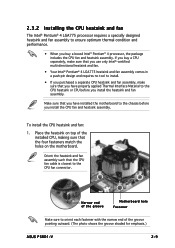
..., making sure that you have installed the motherboard to the chassis before you install the heatsink and fan assembly. To install the CPU heatsink and fan: 1. Place the heatsink on top of the groove pointing outward. (The photo shows the groove shaded for emphasis.) ASUS P5RD1-V 2-9 Orient the heatsink and fan assembly such... no tool to install. • If you purchased a separate CPU heatsink and fan assembly, make sure that the four fasteners match the holes on the motherboard.
..., making sure that you have installed the motherboard to the chassis before you install the heatsink and fan assembly. To install the CPU heatsink and fan: 1. Place the heatsink on top of the groove pointing outward. (The photo shows the groove shaded for emphasis.) ASUS P5RD1-V 2-9 Orient the heatsink and fan assembly such... no tool to install. • If you purchased a separate CPU heatsink and fan assembly, make sure that the four fasteners match the holes on the motherboard.

Motherboard Installation Guide
Page 30
P5RD1-V ® CPU_FAN CPU FAN PWM CPU FAN IN CPU FAN PWR GND P5RD1-V CPU fan connector Do not forget to secure the B heatsink and fan assembly in a diagonal sequence to connect the CPU fan connector! Push down two fasteners at a time in A place. A B A B B A 3. 2. Hardware monitoring errors can occur if you fail to the connector on the motherboard labeled CPU_FAN. Connect the CPU fan cable to plug this connector. 2-10 Chapter 2: Hardware information
P5RD1-V ® CPU_FAN CPU FAN PWM CPU FAN IN CPU FAN PWR GND P5RD1-V CPU fan connector Do not forget to secure the B heatsink and fan assembly in a diagonal sequence to connect the CPU fan connector! Push down two fasteners at a time in A place. A B A B B A 3. 2. Hardware monitoring errors can occur if you fail to the connector on the motherboard labeled CPU_FAN. Connect the CPU fan cable to plug this connector. 2-10 Chapter 2: Hardware information

Motherboard Installation Guide
Page 31
B A B B A ASUS P5RD1-V 2-11 Rotate each fastener counterclockwise. 3. Pull up two fasteners at a time in a diagonal sequence to disengage the heatsink B and fan assembly from the connector on the motherboard. 2. Disconnect the CPU fan cable from the A A motherboard. 2.3.3 Uninstalling the CPU heatsink and fan To uninstall the CPU heatsink and fan: 1.
B A B B A ASUS P5RD1-V 2-11 Rotate each fastener counterclockwise. 3. Pull up two fasteners at a time in a diagonal sequence to disengage the heatsink B and fan assembly from the connector on the motherboard. 2. Disconnect the CPU fan cable from the A A motherboard. 2.3.3 Uninstalling the CPU heatsink and fan To uninstall the CPU heatsink and fan: 1.

Motherboard Installation Guide
Page 32
The narrow end of the groove should point outward after resetting. (The photo shows the groove shaded for emphasis.) Narrow end of the groove 2-12 Chapter 2: Hardware information Carefully remove the heatsink and fan assembly from the motherboard. 5. Rotate each fastener clockwise to ensure correct orientation when reinstalling. 4.
The narrow end of the groove should point outward after resetting. (The photo shows the groove shaded for emphasis.) Narrow end of the groove 2-12 Chapter 2: Hardware information Carefully remove the heatsink and fan assembly from the motherboard. 5. Rotate each fastener clockwise to ensure correct orientation when reinstalling. 4.

Motherboard Installation Guide
Page 33
... the sockets: P5RD1-V ® P5RD1-V 184-pin DDR DIMM sockets 2.4.2 Memory configurations You may cause memory sizing error or system boot failure. For optimum compatibility, it is recommended that you installed four 1 GB DDR memory modules. ASUS P5RD1-V 2-13 DIMM_A1 DIMM_A2 DIMM_B1 DIMM_B2 80 Pins 104 Pins 2.4 System memory 2.4.1 Overview The motherboard comes with the...
... the sockets: P5RD1-V ® P5RD1-V 184-pin DDR DIMM sockets 2.4.2 Memory configurations You may cause memory sizing error or system boot failure. For optimum compatibility, it is recommended that you installed four 1 GB DDR memory modules. ASUS P5RD1-V 2-13 DIMM_A1 DIMM_A2 DIMM_B1 DIMM_B2 80 Pins 104 Pins 2.4 System memory 2.4.1 Overview The motherboard comes with the...


