User Guide
Page 3
Contents Notices...v Safety information vi About this guide vii P5QL-VM DO specifications summary viii Chapter 1: Product introduction 1.1 Before you proceed 1-1 1.2 Motherboard overview 1-2 1.2.1 Motherboard layout 1-2 1.2.2 Layout contents 1-2 1.3 Central Processing Unit (CPU 1-3 1.4 System memory 1-3 1.4.1 ... system 1-18 1.8.2 Support DVD information 1-18 Chapter 2: BIOS information 2.1 Managing and updating your BIOS 2-1 2.1.1 ASUS Update utility 2-1 2.1.2 ASUS EZ Flash 2 utility 2-2 2.1.3 ASUS CrashFree BIOS 3 utility 2-3 2.2 BIOS setup program 2-4 2.3 Main menu 2-4 iii
Contents Notices...v Safety information vi About this guide vii P5QL-VM DO specifications summary viii Chapter 1: Product introduction 1.1 Before you proceed 1-1 1.2 Motherboard overview 1-2 1.2.1 Motherboard layout 1-2 1.2.2 Layout contents 1-2 1.3 Central Processing Unit (CPU 1-3 1.4 System memory 1-3 1.4.1 ... system 1-18 1.8.2 Support DVD information 1-18 Chapter 2: BIOS information 2.1 Managing and updating your BIOS 2-1 2.1.1 ASUS Update utility 2-1 2.1.2 ASUS EZ Flash 2 utility 2-2 2.1.3 ASUS CrashFree BIOS 3 utility 2-3 2.2 BIOS setup program 2-4 2.3 Main menu 2-4 iii
User Guide
Page 7
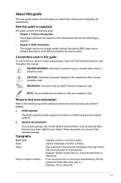
...certain tasks properly, take note of the standard package. How this manual. Detailed descriptions of the motherboard and the new technology it supports. • Chapter 2: BIOS information This chapter tells how to select. CAUTION: Information to prevent damage to the components when... trying to emphasize a word or a phrase. ASUS websites The ASUS website provides updated information on ASUS hardware and software products. 2. Optional ...
...certain tasks properly, take note of the standard package. How this manual. Detailed descriptions of the motherboard and the new technology it supports. • Chapter 2: BIOS information This chapter tells how to select. CAUTION: Information to prevent damage to the components when... trying to emphasize a word or a phrase. ASUS websites The ASUS website provides updated information on ASUS hardware and software products. 2. Optional ...

User Guide
Page 8
... panel I/O ports ** Refer to 10 USB 2.0/1.1 ports (4 ports at mid-board, 6 ports at the back panel) Intel® 82567LF Gigabit LAN Phy controller ASUS CrashFree BIOS 3 ASUS Q-Fan ASUS EZ Flash 2 ASUS MyLogo 2 1 x PS/2 Keyboard port 1 x PS/2 Mouse port 1 x COM port 1 x RJ45 port 1 x VGA port 1 x DVI port 1 x ME switch 6 ...174; 32-bit operating system may only recognize less than 3GB is recommended if you are using a Windows 32-bit operating system. P5QL-VM DO specifications summary CPU Chipset Front Side Bus Memory LGA775 socket for Intel® Core™2 Quad / Core™2 Exreme / Core...
... panel I/O ports ** Refer to 10 USB 2.0/1.1 ports (4 ports at mid-board, 6 ports at the back panel) Intel® 82567LF Gigabit LAN Phy controller ASUS CrashFree BIOS 3 ASUS Q-Fan ASUS EZ Flash 2 ASUS MyLogo 2 1 x PS/2 Keyboard port 1 x PS/2 Mouse port 1 x COM port 1 x RJ45 port 1 x VGA port 1 x DVI port 1 x ME switch 6 ...174; 32-bit operating system may only recognize less than 3GB is recommended if you are using a Windows 32-bit operating system. P5QL-VM DO specifications summary CPU Chipset Front Side Bus Memory LGA775 socket for Intel® Core™2 Quad / Core™2 Exreme / Core...

User Guide
Page 9
ix P5QL-VM DO specifications summary Internal I/O connectors BIOS Accessories Support DVD Form Factor 2 x USB 2.0/1.1 connectors support additional 4 USB 2.0/1.1 ports 6 x SATA connectors 1 x LPT connector 1 x COM connector 1 x Chassis fan connector 1 x CPU... connector 1 x TPM connector 1 x 24-pin EATX power connector 1 x 4-pin ATX 12V power connector 2 x 16Mb Flash ROM, AMI BIOS, PnP, DMI2.0, WfM2.0, SM BIOS 2.5, ACPI2.0a 2 x Serial ATA cables 1 x I/O shield 1 x Support DVD 1 x User Manual Drivers ASUS Update ASUS PC Probe II Intel® IT Director Anti-Virus software (OEM version) uATX form...
ix P5QL-VM DO specifications summary Internal I/O connectors BIOS Accessories Support DVD Form Factor 2 x USB 2.0/1.1 connectors support additional 4 USB 2.0/1.1 ports 6 x SATA connectors 1 x LPT connector 1 x COM connector 1 x Chassis fan connector 1 x CPU... connector 1 x TPM connector 1 x 24-pin EATX power connector 1 x 4-pin ATX 12V power connector 2 x 16Mb Flash ROM, AMI BIOS, PnP, DMI2.0, WfM2.0, SM BIOS 2.5, ACPI2.0a 2 x Serial ATA cables 1 x I/O shield 1 x Support DVD 1 x User Manual Drivers ASUS Update ASUS PC Probe II Intel® IT Director Anti-Virus software (OEM version) uATX form...

User Guide
Page 11
...Keyboard power (3-pin KBPWR) 1-10 10. CPU, Chassis, and Power fan connectors 1-13 11. Optical drive audio in the correct orientation. ATX power connectors (24-pin EATXPWR, 4-pin ATX12V) 1-14 12. Intel CPU socket 1-3 13. DDR2 DIMM sockets 1-3 14. Chassis intrusion connector...P5QL-VM DO Super I/O 7 16Mb 16Mb SATA5 SATA3 SATA1 TPM VIA VT1705 CD PCI3 BIOS BIOS SATA6 SATA4 SATA2 8 F_PANEL USBPW7-10 USB910 USB78 COM2 LPT AAFP 17 16 15 14 13 12 11 10 9 Place six screws into the chassis in connector (4-pin CD) 1-12 9. 1.2 1.2.1 Motherboard overview Motherboard...
...Keyboard power (3-pin KBPWR) 1-10 10. CPU, Chassis, and Power fan connectors 1-13 11. Optical drive audio in the correct orientation. ATX power connectors (24-pin EATXPWR, 4-pin ATX12V) 1-14 12. Intel CPU socket 1-3 13. DDR2 DIMM sockets 1-3 14. Chassis intrusion connector...P5QL-VM DO Super I/O 7 16Mb 16Mb SATA5 SATA3 SATA1 TPM VIA VT1705 CD PCI3 BIOS BIOS SATA6 SATA4 SATA2 8 F_PANEL USBPW7-10 USB910 USB78 COM2 LPT AAFP 17 16 15 14 13 12 11 10 9 Place six screws into the chassis in connector (4-pin CD) 1-12 9. 1.2 1.2.1 Motherboard overview Motherboard...

User Guide
Page 13
...-Sink Package Heat-Sink Package AM4B5708JQJS8E0751C AM4B5808FEWS8E0909C Heat-Sink Package Heat-Sink Package Timing DIMM (BIOS) 4-4-4-12 4-4-4-12 5 5 4 DIMM Support Voltage A* B* C* 2.0~2.1V • • • 1.9~2.1V continued on the motherboard, the actual usable memory for single-channel operation. • For dual-channel configuration,... dependent on its Serial Presence Detect (SPD), which is then mapped for the OS can : - P5Q-VM DO Motherboard Qualified Vendors List (QVL) DDR2-800MHz capability Vendor A-Data A-Data A-Data A-Data Apacer Apacer Corsair Corsair Part No.
...-Sink Package Heat-Sink Package AM4B5708JQJS8E0751C AM4B5808FEWS8E0909C Heat-Sink Package Heat-Sink Package Timing DIMM (BIOS) 4-4-4-12 4-4-4-12 5 5 4 DIMM Support Voltage A* B* C* 2.0~2.1V • • • 1.9~2.1V continued on the motherboard, the actual usable memory for single-channel operation. • For dual-channel configuration,... dependent on its Serial Presence Detect (SPD), which is then mapped for the OS can : - P5Q-VM DO Motherboard Qualified Vendors List (QVL) DDR2-800MHz capability Vendor A-Data A-Data A-Data A-Data Apacer Apacer Corsair Corsair Part No.

User Guide
Page 14
... DS Micron 8AG27 D9JWB OCZ2G800R22GK 1024MB DS OCZ Heat-Sink Package OCZ2P800R22GK 1024MB DS OCZ Heat-Sink Package (continued on the next page) Timing DIMM (BIOS) 5 5 5 4-4-4-12 4-4-4-12 4-4-4-12 5-5-5-15 DIMM Support Voltage A* B* C 4 • •• 5 • •• 4 • •• 5 •• 5 • &#...1.8V 6 1.8V • 5-5-5-15 2.0V • 5 1.8V • 6 1.8V • 6 1.8V • 6-6-6-12 • 6-6-6-12 • 4-5-5-15 2.0V • 4-4-4-15 1.9 • - 2.1 V ASUS P5QL-VM DO 1-5 Vendor Part No.
... DS Micron 8AG27 D9JWB OCZ2G800R22GK 1024MB DS OCZ Heat-Sink Package OCZ2P800R22GK 1024MB DS OCZ Heat-Sink Package (continued on the next page) Timing DIMM (BIOS) 5 5 5 4-4-4-12 4-4-4-12 4-4-4-12 5-5-5-15 DIMM Support Voltage A* B* C 4 • •• 5 • •• 4 • •• 5 •• 5 • &#...1.8V 6 1.8V • 5-5-5-15 2.0V • 5 1.8V • 6 1.8V • 6 1.8V • 6-6-6-12 • 6-6-6-12 • 4-5-5-15 2.0V • 4-4-4-15 1.9 • - 2.1 V ASUS P5QL-VM DO 1-5 Vendor Part No.

User Guide
Page 16
...1G 1024MB Transcend JM667QLJ-1G 1024MB Transcend JM667QLU-2G 2048MB Twinmos 8D-A3JK5MPETP 512MB SS/ Chip DS Brand Chip No. ASUS P5QL-VM DO 1-7 Double - DS GEIL Heat-Sink Package DS GEIL Heat-Sink Package SS Kingmax KKEA88B4LAUG-29DX DS Kingmax ... Samsung K4T2G084QA-HCE6 DS Super Talent PG 64M8-800 0750 SS Transced TQ243PCF8T0838 DS Elpida E5108AJBG-6E-E DS Transced TQ243PCF8T0834 SS PSC A3R12E3GEF633ACAOY Timing DIMM (BIOS) 5 5 5 5 5 5 5 5 5 5 5 5 5 5 5 DIMM Support Voltage A* B* C 1.8V 1.8V 1.8V 1.8V • • • SS - sided DIMM support: ...
...1G 1024MB Transcend JM667QLJ-1G 1024MB Transcend JM667QLU-2G 2048MB Twinmos 8D-A3JK5MPETP 512MB SS/ Chip DS Brand Chip No. ASUS P5QL-VM DO 1-7 Double - DS GEIL Heat-Sink Package DS GEIL Heat-Sink Package SS Kingmax KKEA88B4LAUG-29DX DS Kingmax ... Samsung K4T2G084QA-HCE6 DS Super Talent PG 64M8-800 0750 SS Transced TQ243PCF8T0838 DS Elpida E5108AJBG-6E-E DS Transced TQ243PCF8T0834 SS PSC A3R12E3GEF633ACAOY Timing DIMM (BIOS) 5 5 5 5 5 5 5 5 5 5 5 5 5 5 5 DIMM Support Voltage A* B* C 1.8V 1.8V 1.8V 1.8V • • • SS - sided DIMM support: ...

User Guide
Page 17
...screw. 6. Remove the bracket opposite the slot that comply with the slot and press firmly until the card is already installed in a chassis). 3. Turn on BIOS setup. 2. Install the software drivers for the card. 2. Assign an IRQ to the card. 3. When using PCI cards on the slot. 5. Remove ...the chassis cover (if your motherboard is completely seated on shared slots, ensure that the drivers support "Share IRQ" or that they support. Unplug the power cord before adding or removing...
...screw. 6. Remove the bracket opposite the slot that comply with the slot and press firmly until the card is already installed in a chassis). 3. Turn on BIOS setup. 2. Install the software drivers for the card. 2. Assign an IRQ to the card. 3. When using PCI cards on the slot. 5. Remove ...the chassis cover (if your motherboard is completely seated on shared slots, ensure that the drivers support "Share IRQ" or that they support. Unplug the power cord before adding or removing...

User Guide
Page 18
... pins 1-2. 3. Hold down and cut off the AC power, then reboot the system, the BIOS automatically resets parameter settings to pins 2-3. KBPWR 12 23 +5V +5VSB (Default) P5QL-VM DO P5QL-VM DO Keyboard Power Setting ASUS P5QL-VM DO 1-9 Except when clearing the RTC RAM, never remove the cap on the keyboard (the...set this jumper to enable or disable the keyboard wake-up the computer by erasing the CMOS RTC RAM data. This feature requires an ATX power supply that can clear the CMOS memory of date, time, and system setup parameters by pressing a key on CLRTC jumper default ...
... pins 1-2. 3. Hold down and cut off the AC power, then reboot the system, the BIOS automatically resets parameter settings to pins 2-3. KBPWR 12 23 +5V +5VSB (Default) P5QL-VM DO P5QL-VM DO Keyboard Power Setting ASUS P5QL-VM DO 1-9 Except when clearing the RTC RAM, never remove the cap on the keyboard (the...set this jumper to enable or disable the keyboard wake-up the computer by erasing the CMOS RTC RAM data. This feature requires an ATX power supply that can clear the CMOS memory of date, time, and system setup parameters by pressing a key on CLRTC jumper default ...

User Guide
Page 20
... function of the audio ports in 2, 4, or 6-channel configuration. Microphone port (pink). Push the switch to ON/OFF labelled on the I . 11. USB 2.0 ports 3, 4, 5, and 6. ASUS P5QL-VM DO 1-11 LAN port LED indications ACT/LINK LED Status Description OFF No link ORANGE Linked BLINKING Data activity SPEED LED Status Description OFF 10... below for pointing devices or other audio sources. 5. Refer to enable or disable the Intel® ME function. Disable Intel® ME function before updating BIOS. 8. USB 2.0 ports 1 and 2. DVI port.
... function of the audio ports in 2, 4, or 6-channel configuration. Microphone port (pink). Push the switch to ON/OFF labelled on the I . 11. USB 2.0 ports 3, 4, 5, and 6. ASUS P5QL-VM DO 1-11 LAN port LED indications ACT/LINK LED Status Description OFF No link ORANGE Linked BLINKING Data activity SPEED LED Status Description OFF 10... below for pointing devices or other audio sources. 5. Refer to enable or disable the Intel® ME function. Disable Intel® ME function before updating BIOS. 8. USB 2.0 ports 1 and 2. DVI port.
User Guide
Page 24
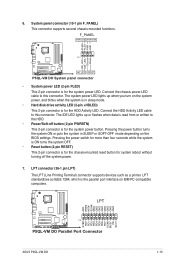
6. Ground Reset P5QL-VM DO HD_LED RESET P5QL-VM DO System panel connector • System power LED (2-pin PLED) This 2-pin connector is for system reboot without turning off button (2-... GND GND GND GND GND GND GND GND STB# PD0 PD1 PD2 PD3 PD4 PD5 PD6 PD7 ACK# BUSY PE SLCT P5QL-VM DO PIN 1 P5QL-VM DO Parallel Port Connector ASUS P5QL-VM DO 1-15 LPT standardizes as a printer. Connect the HDD Activity LED cable to the HDD. • Power/Soft-off... ON turns the system OFF. • Reset button (2-pin RESET) This 2-pin connector is the parallel port interface on the BIOS settings.
6. Ground Reset P5QL-VM DO HD_LED RESET P5QL-VM DO System panel connector • System power LED (2-pin PLED) This 2-pin connector is for system reboot without turning off button (2-... GND GND GND GND GND GND GND GND STB# PD0 PD1 PD2 PD3 PD4 PD5 PD6 PD7 ACK# BUSY PE SLCT P5QL-VM DO PIN 1 P5QL-VM DO Parallel Port Connector ASUS P5QL-VM DO 1-15 LPT standardizes as a printer. Connect the HDD Activity LED cable to the HDD. • Power/Soft-off... ON turns the system OFF. • Reset button (2-pin RESET) This 2-pin connector is the parallel port interface on the BIOS settings.

User Guide
Page 25
... Panel Type item in the BIOS is for a chassis-mounted intrusion detection sensor or switch. GND PRESENCE# SENSE1_RETUR SENSE2_RETUR AGND NC NC NC AAFP PIN 1 PIN 1 MIC2 MICPWR Line out_R NC Line out_L PORT1 L PORT1 R PORT2 R SENSE_SEND PORT2 L P5QL-VM DO HD-audio-compliant Legacy... detection feature. Front panel audio connector (10-1 pin AAFP) This connector is for details. 9. CHASSIS GND Chassis Signal P5QL-VM DO +5VSB_MB P5QL-VM DO Chassis intrusion connector 1-16 Chapter 1: Product introduction Remove the jumper caps only when you want to connect a high-...
... Panel Type item in the BIOS is for a chassis-mounted intrusion detection sensor or switch. GND PRESENCE# SENSE1_RETUR SENSE2_RETUR AGND NC NC NC AAFP PIN 1 PIN 1 MIC2 MICPWR Line out_R NC Line out_L PORT1 L PORT1 R PORT2 R SENSE_SEND PORT2 L P5QL-VM DO HD-audio-compliant Legacy... detection feature. Front panel audio connector (10-1 pin AAFP) This connector is for details. 9. CHASSIS GND Chassis Signal P5QL-VM DO +5VSB_MB P5QL-VM DO Chassis intrusion connector 1-16 Chapter 1: Product introduction Remove the jumper caps only when you want to connect a high-...

User Guide
Page 28
... menu appears. 2. From the Windows® desktop, Click Start > Programs > ASUS > ASUS Update > ASUS Update to complete the installation. Chapter 2 BIOS information 2.1 Managing and updating your BIOS Save a copy of the original motherboard BIOS file to a USB flash disk in case you need to restore the BIOS in the Support DVD that allows you to manage, save, and...
... menu appears. 2. From the Windows® desktop, Click Start > Programs > ASUS > ASUS Update > ASUS Update to complete the installation. Chapter 2 BIOS information 2.1 Managing and updating your BIOS Save a copy of the original motherboard BIOS file to a USB flash disk in case you need to restore the BIOS in the Support DVD that allows you to manage, save, and...
User Guide
Page 29
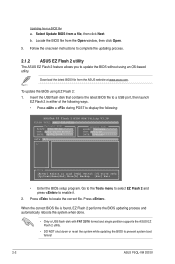
Locate the BIOS file from the ASUS website at www.asus.com. Download the latest BIOS file from the Open window, then click Open. 3. Press to display the following: ASUSTek EZ Flash 2 BIOS ROM Utility V3.38 FLASH TYPE: MXIC 25L1605A Current ROM BOARD: P5Q-VM DO VER: 0211 (H:00 B:06) ... process. 2.1.2 ASUS EZ Flash 2 utility The ASUS EZ Flash 2 feature allows you to update the BIOS without using EZ Flash 2: 1. To update the BIOS using an OS‑based utility. Go to the Tools menu to select EZ Flash 2 and press to prevent system boot failure! 2-2 ASUS P5QL-VM DO/SI
Locate the BIOS file from the ASUS website at www.asus.com. Download the latest BIOS file from the Open window, then click Open. 3. Press to display the following: ASUSTek EZ Flash 2 BIOS ROM Utility V3.38 FLASH TYPE: MXIC 25L1605A Current ROM BOARD: P5Q-VM DO VER: 0211 (H:00 B:06) ... process. 2.1.2 ASUS EZ Flash 2 utility The ASUS EZ Flash 2 feature allows you to update the BIOS without using EZ Flash 2: 1. To update the BIOS using an OS‑based utility. Go to the Tools menu to select EZ Flash 2 and press to prevent system boot failure! 2-2 ASUS P5QL-VM DO/SI

User Guide
Page 30
2.1.3 ASUS CrashFree BIOS 3 utility The ASUS CrashFree BIOS 3 is an auto recovery tool that contains the updated BIOS file. • Prepare the motherboard Support DVD or a USB flash disk containing the updated motherboard BIOS before using this motherboard. Recovering the BIOS To recover the BIOS: 1. Bad BIOS checksum. Checking for CD-ROM... Bad BIOS checksum. Start Programming... 3. Doing so can update a corrupted BIOS file using...
2.1.3 ASUS CrashFree BIOS 3 utility The ASUS CrashFree BIOS 3 is an auto recovery tool that contains the updated BIOS file. • Prepare the motherboard Support DVD or a USB flash disk containing the updated motherboard BIOS before using this motherboard. Recovering the BIOS To recover the BIOS: 1. Bad BIOS checksum. Checking for CD-ROM... Bad BIOS checksum. Start Programming... 3. Doing so can update a corrupted BIOS file using...

User Guide
Page 31
... to set the system date. 2-4 ASUS P5QL-VM DO/SI Using the power button, reset button, or the ++ keys to force reset from the operating system. • The default BIOS settings for this motherboard apply to most conditions to download the latest BIOS file for reference only. This section ... Setup Defaults item under the Exit menu. Use [+] or [-] to "Run Setup." 2.2 BIOS setup program Use the BIOS Setup program when you are for this motherboard. 2.3 Main menu When you enter the BIOS Setup program, the Main menu screen appears, giving you an overview of the following procedures: ...
... to set the system date. 2-4 ASUS P5QL-VM DO/SI Using the power button, reset button, or the ++ keys to force reset from the operating system. • The default BIOS settings for this motherboard apply to most conditions to download the latest BIOS file for reference only. This section ... Setup Defaults item under the Exit menu. Use [+] or [-] to "Run Setup." 2.2 BIOS setup program Use the BIOS Setup program when you are for this motherboard. 2.3 Main menu When you enter the BIOS Setup program, the Main menu screen appears, giving you an overview of the following procedures: ...

User Guide
Page 32
... [IDE] Sets the configuration for each SATA device. Configuration options: [Disabled] [Auto] Block (Multi-Sector Transfer) M [Auto] Enables or disables data multi-sectors transfers. Chapter 2: BIOS information 2-5 Configuration options: [Auto] [0] [1] [2] [3] [4] DMA Mode [Auto] Selects the DMA mode. Select a device item then press to [Auto] enables the LBA mode if...system. Configuration options: [Not Installed] [Auto] [CDROM] [ARMD] LBA/Large Mode [Auto] Enables or disables the LBA mode. 2.3.3 SATA 1-6 While entering Setup, the BIOS automatically detects the presence of IDE drive.
... [IDE] Sets the configuration for each SATA device. Configuration options: [Disabled] [Auto] Block (Multi-Sector Transfer) M [Auto] Enables or disables data multi-sectors transfers. Chapter 2: BIOS information 2-5 Configuration options: [Auto] [0] [1] [2] [3] [4] DMA Mode [Auto] Selects the DMA mode. Select a device item then press to [Auto] enables the LBA mode if...system. Configuration options: [Not Installed] [Auto] [CDROM] [ARMD] LBA/Large Mode [Auto] Enables or disables the LBA mode. 2.3.3 SATA 1-6 While entering Setup, the BIOS automatically detects the presence of IDE drive.

User Guide
Page 33
... items allow you to individually set overclocking parameters. Overclock Profile - Select either one of the general system specifications. BIOS SETUP UTILITY Main AI Tweaker Advanced Power Boot Tools Configure System Performance Settings Ai Overclock Tuner DRAM Frequency Configure DRAM ... desired CPU internal frequency. Loads the overclock profile. 2-6 ASUS P5QL-VM DO/SI Hard Disk Write Protect [Disabled] Disables or enables device write protection. This will be effective only if device is accessed throuh BIOS. Confiuration option: [Disabled] [Enabled] IDE Detect Time ...
... items allow you to individually set overclocking parameters. Overclock Profile - Select either one of the general system specifications. BIOS SETUP UTILITY Main AI Tweaker Advanced Power Boot Tools Configure System Performance Settings Ai Overclock Tuner DRAM Frequency Configure DRAM ... desired CPU internal frequency. Loads the overclock profile. 2-6 ASUS P5QL-VM DO/SI Hard Disk Write Protect [Disabled] Disables or enables device write protection. This will be effective only if device is accessed throuh BIOS. Confiuration option: [Disabled] [Enabled] IDE Detect Time ...

User Guide
Page 34
... and PCI bus. to 1.30V with the FSB Frequency item settings. The values range from 1.20V to adjust the value. Configure DRAM Timing by the BIOS. Chapter 2: BIOS information 2-7 Input the desired CPU frequency using the numeric keypad. to 800. FSB Frequency [XXX] Displays the frequency sent by the clock generator to...
... and PCI bus. to 1.30V with the FSB Frequency item settings. The values range from 1.20V to adjust the value. Configure DRAM Timing by the BIOS. Chapter 2: BIOS information 2-7 Input the desired CPU frequency using the numeric keypad. to 800. FSB Frequency [XXX] Displays the frequency sent by the clock generator to...


