
User Manual
Page 4
...panel connectors 1-29 1.10.2 Internal connectors 1-30 1.11 Starting up for the first time 1-39 1.12 Turning off the computer 1-40 1.12.1 Using the OS shut down function 1-40 1.12.2 Using the dual function power switch 1-40 Chapter 2: BIOS setup 2.1 Managing and updating your BIOS 2-2 2.1.1 ASUS... Update utility 2-2 2.1.2 Creating a bootable floppy disk 2-5 2.1.3 ASUS EZ Flash 2 utility 2-6 2.1.4 AFUDOS utility 2-7 2.1.5 ASUS CrashFree BIOS 3 utility 2-9 2.2 BIOS setup program 2-10 2.2.1 BIOS menu ...
...panel connectors 1-29 1.10.2 Internal connectors 1-30 1.11 Starting up for the first time 1-39 1.12 Turning off the computer 1-40 1.12.1 Using the OS shut down function 1-40 1.12.2 Using the dual function power switch 1-40 Chapter 2: BIOS setup 2.1 Managing and updating your BIOS 2-2 2.1.1 ASUS... Update utility 2-2 2.1.2 Creating a bootable floppy disk 2-5 2.1.3 ASUS EZ Flash 2 utility 2-6 2.1.4 AFUDOS utility 2-7 2.1.5 ASUS CrashFree BIOS 3 utility 2-9 2.2 BIOS setup program 2-10 2.2.1 BIOS menu ...

User Manual
Page 12
P5Q SE Plus specifications summary USB 12 x USB 2.0 ports (6 ports at mid-board, 6 ports at 1MHz increment - FSB tuning from 200MHz to 1333MHz for DDR2 - PCI Express frequency tuning from 667MHz up to 800 MHz at back panel) ASUS Exclusive Overclocking Features Intelligent ... 1 x COM connector 1 x S/PDIF Out header 1 x Chassis intrusion connector 1 x Front panel audio connector 1 x CD audio in connector 1 x 24-pin ATX power connector 1 x 4-pin ATX 12V power connector System panel connector (Q-Connector) WfM 2.0, DMI 2.0, WOL by PME, WOR by PME, PXE BIOS Features 8Mb...
P5Q SE Plus specifications summary USB 12 x USB 2.0 ports (6 ports at mid-board, 6 ports at 1MHz increment - FSB tuning from 200MHz to 1333MHz for DDR2 - PCI Express frequency tuning from 667MHz up to 800 MHz at back panel) ASUS Exclusive Overclocking Features Intelligent ... 1 x COM connector 1 x S/PDIF Out header 1 x Chassis intrusion connector 1 x Front panel audio connector 1 x CD audio in connector 1 x 24-pin ATX power connector 1 x 4-pin ATX 12V power connector System panel connector (Q-Connector) WfM 2.0, DMI 2.0, WOL by PME, WOR by PME, PXE BIOS Features 8Mb...

User Manual
Page 17
... module eliminates the trouble of fan speed to the motherboard. Profile The motherboard features the ASUS O.C. See page 1-38 for details. The BIOS settings can continue running at a time and avoiding wrong cable connections. ASUS P5Q SE Plus 1-5 To wake the system and return to share ... the system panel cables one at minimum power and noise when you to easily connect or disconnect the chassis front panel cables to achieve a quiet and cool environment. ASUS Q-Connector ASUS Q-Connector allows you are temporarily away. ASUS Quiet Thermal Solution ASUS Quiet Thermal ...
... module eliminates the trouble of fan speed to the motherboard. Profile The motherboard features the ASUS O.C. See page 1-38 for details. The BIOS settings can continue running at a time and avoiding wrong cable connections. ASUS P5Q SE Plus 1-5 To wake the system and return to share ... the system panel cables one at minimum power and noise when you to easily connect or disconnect the chassis front panel cables to achieve a quiet and cool environment. ASUS Q-Connector ASUS Q-Connector allows you are temporarily away. ASUS Quiet Thermal Solution ASUS Quiet Thermal ...

User Manual
Page 21
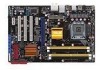
1.5.3 Motherboard layout Refer to 1.10 Connectors for more information about rear panel connectors and internal connectors. ASUS P5Q SE Plus 1-9
1.5.3 Motherboard layout Refer to 1.10 Connectors for more information about rear panel connectors and internal connectors. ASUS P5Q SE Plus 1-9

User Manual
Page 41
... 8-channel configuration. This port is for the LAN port LED indications. Microphone port (pink). ASUS P5Q SE Plus 1-29 Center/Subwoofer port (orange). This port connects the tape, CD, DVD player, or other audio sources. 6. 1.10 Connectors 1.10.1 Rear panel connectors 1. ��P��S�/2��m��o�u�s�e�p�...
... 8-channel configuration. This port is for the LAN port LED indications. Microphone port (pink). ASUS P5Q SE Plus 1-29 Center/Subwoofer port (orange). This port connects the tape, CD, DVD player, or other audio sources. 6. 1.10 Connectors 1.10.1 Rear panel connectors 1. ��P��S�/2��m��o�u�s�e�p�...

User Manual
Page 45
... card. Connect the USB module cable to any of the system chassis. ASUS P5Q SE Plus 1-33 These USB connectors comply with USB 2.0 specification that supports up to the USB connector onboard if your chassis supports front panel USB ports. The USB module cable is purchased separately. 6. You can ...connect the front panel USB cable to the ASUS Q-Connector (USB, blue) first, and then install the Q-Connector (USB) to ...
... card. Connect the USB module cable to any of the system chassis. ASUS P5Q SE Plus 1-33 These USB connectors comply with USB 2.0 specification that supports up to the USB connector onboard if your chassis supports front panel USB ports. The USB module cable is purchased separately. 6. You can ...connect the front panel USB cable to the ASUS Q-Connector (USB, blue) first, and then install the Q-Connector (USB) to ...

User Manual
Page 47
..., set the item to [HD Audio]; ASUS P5Q SE Plus 1-35 By default, the pin labeled "Chassis Signal" and "Ground" are shorted with a jumper cap. Connect one end of the front panel audio I /O module that you connect a high-definition front panel audio module to this connector to avail of the motherboard's high-definition audio capability. • If...
..., set the item to [HD Audio]; ASUS P5Q SE Plus 1-35 By default, the pin labeled "Chassis Signal" and "Ground" are shorted with a jumper cap. Connect one end of the front panel audio I /O module that you connect a high-definition front panel audio module to this connector to avail of the motherboard's high-definition audio capability. • If...

User Manual
Page 49
...-8 pin PANEL) This connector supports several chassis-mounted functions. • System power LED (2-pin PLED) This 2-pin connector is read from or written to this connector. The IDE LED lights up when you to this connector. ASUS P5Q SE Plus 1-37 Connect the HDD Activity LED cable to hear system beeps and warnings. • ATX power...
...-8 pin PANEL) This connector supports several chassis-mounted functions. • System power LED (2-pin PLED) This 2-pin connector is read from or written to this connector. The IDE LED lights up when you to this connector. ASUS P5Q SE Plus 1-37 Connect the HDD Activity LED cable to hear system beeps and warnings. • ATX power...

User Manual
Page 50
... detailed pin definitions, then match them to the respective front panel cable labels. 2. Refer to install the ASUS Q-Connector. 1. ASUS Q-Connector (system panel) You can use the ASUS Q-Connector to the ASUS Q-Connector. Refer to the instructions below to the labels on the motherboard. Enable the front panel functions. The figure shows the Q-Connector properly installed on the...
... detailed pin definitions, then match them to the respective front panel cable labels. 2. Refer to install the ASUS Q-Connector. 1. ASUS Q-Connector (system panel) You can use the ASUS Q-Connector to the ASUS Q-Connector. Refer to the instructions below to the labels on the motherboard. Enable the front panel functions. The figure shows the Q-Connector properly installed on the...

User Manual
Page 51
... then runs the power-on the screen. While the tests are off. 3. Follow the instructions in the following order: a. ASUS P5Q SE Plus 1-39 External SCSI devices (starting with ATX power supplies, the system LED lights up . For systems with the last device on test. Monitor b. BIOS Beep One short...making all switches are running, the BIOS beeps (see anything within 30 seconds from the time you press the ATX power button. At power on the system front panel case lights up when you turned on the power, the system may light up or switch between orange and...
... then runs the power-on the screen. While the tests are off. 3. Follow the instructions in the following order: a. ASUS P5Q SE Plus 1-39 External SCSI devices (starting with ATX power supplies, the system LED lights up . For systems with the last device on test. Monitor b. BIOS Beep One short...making all switches are running, the BIOS beeps (see anything within 30 seconds from the time you press the ATX power button. At power on the system front panel case lights up when you turned on the power, the system may light up or switch between orange and...

User Manual
Page 78
... High Definition Audio [Enabled] Allows you to legacy AC'97 or high-definition audio depending on the audio standard that the front panel audio module supports. Change Option F1 General Help F10 Save and Exit ESC Exit v02.61 (C)Copyright 1985-2008, American Megatrends, Inc...when you to enable or disable the High Definition Audio. 2.5.3 OnBoard Devices Configuration BIOS SETUP UTILITY Advanced Onboard Device Configuraiton High Definition Audio Front Panel Type J-Micron eSATA/PATA Controller Onboard PCIE LAN Onboard PCIE LAN Boot ROM [Enabled] [HD Audio] [Enabled] [Enabled] [Disabled] ...
... High Definition Audio [Enabled] Allows you to legacy AC'97 or high-definition audio depending on the audio standard that the front panel audio module supports. Change Option F1 General Help F10 Save and Exit ESC Exit v02.61 (C)Copyright 1985-2008, American Megatrends, Inc...when you to enable or disable the High Definition Audio. 2.5.3 OnBoard Devices Configuration BIOS SETUP UTILITY Advanced Onboard Device Configuraiton High Definition Audio Front Panel Type J-Micron eSATA/PATA Controller Onboard PCIE LAN Onboard PCIE LAN Boot ROM [Enabled] [HD Audio] [Enabled] [Enabled] [Disabled] ...


