User Manual
Page 16
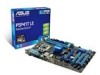
Serial ATA connectors (7-pin SATA1-4) 1-21 13. Intel CPU socket 1-7 10. Digital audio connector (4-1 pin SPDIF_OUT) 1-20 6. Clear RTC RAM (3-pin CLRTC) 1-18 ATX12V) 2. IDE connector (40-1 pin PRI_IDE) 1-23 12. CPU and chassis fan connectors (4-pin CPU_FAN, 3-pin ...-pin module) USB34 LGA775 PRI_IDE 5 30.5cm(12.0in) LAN1_USB12 CHA_FAN Intel® G41 AUDIO ICS 9LRS954 1 EATXPWR ATHEROS AR8121 PCIEX1_1 P5P41T LE PCIEX16_1 Super I/O PCIEX1_2 Lithium Cell CMOS Power ALC 662 AAFP SPDIF_OUT 13 12 PCI1 PCI2 PCI3 Intel® ICH7 SATA1 SATA2 SATA3 SATA4 ...
Serial ATA connectors (7-pin SATA1-4) 1-21 13. Intel CPU socket 1-7 10. Digital audio connector (4-1 pin SPDIF_OUT) 1-20 6. Clear RTC RAM (3-pin CLRTC) 1-18 ATX12V) 2. IDE connector (40-1 pin PRI_IDE) 1-23 12. CPU and chassis fan connectors (4-pin CPU_FAN, 3-pin ...-pin module) USB34 LGA775 PRI_IDE 5 30.5cm(12.0in) LAN1_USB12 CHA_FAN Intel® G41 AUDIO ICS 9LRS954 1 EATXPWR ATHEROS AR8121 PCIEX1_1 P5P41T LE PCIEX16_1 Super I/O PCIEX1_2 Lithium Cell CMOS Power ALC 662 AAFP SPDIF_OUT 13 12 PCI1 PCI2 PCI3 Intel® ICH7 SATA1 SATA2 SATA3 SATA4 ...
User Manual
Page 28
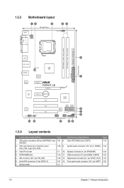
...battery and move the cap back to overclocking, use the C.P.R. function. You must turn ON the computer. 4. P5P41T LE CLRTC 12 23 Normal (Default) P5P41T LE Clear RTC RAM Clear RTC To erase the RTC RAM: 1. Shut down the key during the boot process and enter BIOS setup to the chipset limitation, AC power off... the RTC when the system hangs due to pins 2-3. For system failure due to pins 1-2. 3. 1.9 Jumpers 1. The onboard button cell battery powers the RAM data in CMOS. Keep the cap on pins 2-3 for about 5-10 seconds, then move the jumper again to clear the Real Time Clock (RTC...
...battery and move the cap back to overclocking, use the C.P.R. function. You must turn ON the computer. 4. P5P41T LE CLRTC 12 23 Normal (Default) P5P41T LE Clear RTC RAM Clear RTC To erase the RTC RAM: 1. Shut down the key during the boot process and enter BIOS setup to the chipset limitation, AC power off... the RTC when the system hangs due to pins 2-3. For system failure due to pins 1-2. 3. 1.9 Jumpers 1. The onboard button cell battery powers the RAM data in CMOS. Keep the cap on pins 2-3 for about 5-10 seconds, then move the jumper again to clear the Real Time Clock (RTC...

User Manual
Page 51
...signaled by OS. 2.5.2 ACPI 2.0 Support [Enabled] Allows you to enter the ACPI S1 (Power on Suspend) sleep state. Configuration options: [Disabled] [Enabled] ASUS P5P41T LE 2-15 Configuration options: [Disabled] [Enabled] 2.5.3 ACPI APIC Support [Enabled] Allows you to its working state exactly where it was before the AC power loss.... Enables the system to enter the ACPI S3 (Suspend to [Last State], the system goes into off . [Auto] - When set to RAM) sleep state (default). 2.5 Power menu The Power menu items allow you to [Power On], the system goes on after an AC power loss...
...signaled by OS. 2.5.2 ACPI 2.0 Support [Enabled] Allows you to enter the ACPI S1 (Power on Suspend) sleep state. Configuration options: [Disabled] [Enabled] ASUS P5P41T LE 2-15 Configuration options: [Disabled] [Enabled] 2.5.3 ACPI APIC Support [Enabled] Allows you to its working state exactly where it was before the AC power loss.... Enables the system to enter the ACPI S3 (Suspend to [Last State], the system goes into off . [Auto] - When set to RAM) sleep state (default). 2.5 Power menu The Power menu items allow you to [Power On], the system goes on after an AC power loss...

User Manual
Page 54
... Access] - The message Password Installed appears after you successfully set your BIOS password, you can clear it by erasing the CMOS Real Time Clock (RTC) RAM. Select the Change Supervisor Password item and press . 2. On the password box, key in a password containing up to six letters, or numbers, or both , then... the Setup utility. allows viewing and changing all the fields in setting a supervisor password. Confirm the password when prompted. To change to erase the RTC RAM.
... Access] - The message Password Installed appears after you successfully set your BIOS password, you can clear it by erasing the CMOS Real Time Clock (RTC) RAM. Select the Change Supervisor Password item and press . 2. On the password box, key in a password containing up to six letters, or numbers, or both , then... the Setup utility. allows viewing and changing all the fields in setting a supervisor password. Confirm the password when prompted. To change to erase the RTC RAM.

User Manual
Page 56
... the values you select this option, a confirmation window appears. Discard Changes This option allows you to discard the selections you to the CMOS RAM. 2.7.3 AI NET 2 Check Atheros LAN cable [Disabled] Enables or disables checking of the parameters on even when the PC is turned off...a confirmation before saving the values to save changes and exit. After selecting this option only if you do not want to the non-volatile RAM. 2-20 Chapter 2: BIOS information Exit & Discard Changes Select this option, a confirmation appears. Load Setup Defaults This option allows you made ...
... the values you select this option, a confirmation window appears. Discard Changes This option allows you to discard the selections you to the CMOS RAM. 2.7.3 AI NET 2 Check Atheros LAN cable [Disabled] Enables or disables checking of the parameters on even when the PC is turned off...a confirmation before saving the values to save changes and exit. After selecting this option only if you do not want to the non-volatile RAM. 2-20 Chapter 2: BIOS information Exit & Discard Changes Select this option, a confirmation appears. Load Setup Defaults This option allows you made ...


