
User Manual
Page 1
P5MT-M Motherboard
P5MT-M Motherboard

User Manual
Page 3
Contents Notices vi Safety information vii About this guide viii P5MT-M specifications summary x Chapter 1: Product introduction 1.1 Welcome 1-1 1.2 Package contents 1-1 1.3 Special features 1-2 1.3.1 Product highlights 1-2 1.3.2 Innovative ASUS features 1-4 Chapter 2: Hardware information 2.1 Before you proceed 2-1 2.2 Motherboard overview 2-2 2.2.1 Placement direction 2-2 2.2.2 Screw holes 2-2 2.2.3 Motherboard layout 2-3 2.2.4 Layout contents 2-4 2.3 Central Processing Unit (CPU 2-6 2.3.1 Installing the CPU 2-6 2.3.2 Installing the CPU heatsink and fan...
Contents Notices vi Safety information vii About this guide viii P5MT-M specifications summary x Chapter 1: Product introduction 1.1 Welcome 1-1 1.2 Package contents 1-1 1.3 Special features 1-2 1.3.1 Product highlights 1-2 1.3.2 Innovative ASUS features 1-4 Chapter 2: Hardware information 2.1 Before you proceed 2-1 2.2 Motherboard overview 2-2 2.2.1 Placement direction 2-2 2.2.2 Screw holes 2-2 2.2.3 Motherboard layout 2-3 2.2.4 Layout contents 2-4 2.3 Central Processing Unit (CPU 2-6 2.3.1 Installing the CPU 2-6 2.3.2 Installing the CPU heatsink and fan...

User Manual
Page 7
...circuitry. • Avoid dust, humidity, and temperature extremes. Contact a qualified service technician or your area. Operation safety • Before installing the motherboard and adding devices on a stable surface. • If you detect any area where it may become wet. • Place the product on...not sure about the voltage of the electrical outlet you add a device. • Before connecting or removing signal cables from the motherboard, ensure that all power cables from the existing system before the signal cables are unplugged. • Seek professional assistance before using...
...circuitry. • Avoid dust, humidity, and temperature extremes. Contact a qualified service technician or your area. Operation safety • Before installing the motherboard and adding devices on a stable surface. • If you detect any area where it may become wet. • Place the product on...not sure about the voltage of the electrical outlet you add a device. • Before connecting or removing signal cables from the motherboard, ensure that all power cables from the existing system before the signal cables are unplugged. • Seek professional assistance before using...
User Manual
Page 8
Refer to the ASUS contact information. 2. viii ASUS websites The ASUS website provides updated information on the motherboard. • Chapter 3: Powering up This chapter describes the power up sequence, the vocal POST messages, and ways of the standard... system components. About this guide This user guide contains the information you may refer to when configuring the motherboard. It includes description of the switches, jumpers, and connectors on ASUS hardware and software products. These documents are also provided. • Chapter 5: RAID support Provides information on...
Refer to the ASUS contact information. 2. viii ASUS websites The ASUS website provides updated information on the motherboard. • Chapter 3: Powering up This chapter describes the power up sequence, the vocal POST messages, and ways of the standard... system components. About this guide This user guide contains the information you may refer to when configuring the motherboard. It includes description of the switches, jumpers, and connectors on ASUS hardware and software products. These documents are also provided. • Chapter 5: RAID support Provides information on...

User Manual
Page 13
This chapter describes the motherboard features and the new technologies it supports. 1Product introduction
This chapter describes the motherboard features and the new technologies it supports. 1Product introduction
User Manual
Page 15
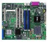
... standout in -1 disk drive cable 4 x Serial ATA signal cables 2 x Serial ATA power cable 1 x USB PCI cable bracket I/O shield ASUS motherboard support CD User guide If any of ASUS quality motherboards! ASUS P5MT-M 1-1 Before you for the following items. Motherboard ASUS P5MT-M motherboard Cables Accessories Application CD Documentation 2-in the long line of the above items is damaged or missing, contact...
... standout in -1 disk drive cable 4 x Serial ATA signal cables 2 x Serial ATA power cable 1 x USB PCI cable bracket I/O shield ASUS motherboard support CD User guide If any of ASUS quality motherboards! ASUS P5MT-M 1-1 Before you for the following items. Motherboard ASUS P5MT-M motherboard Cables Accessories Application CD Documentation 2-in the long line of the above items is damaged or missing, contact...

User Manual
Page 16
...lower pin count, reduced voltage requirement, and up to ensure data security and enable powerful multi-task processing. DDR2 memory support The motherboard supports DDR2 memory, which features data transfer rates of 667 MHz or 533 MHz to meet the higher bandwidth requirements of system memory ...® Pentium® D processor in the 775-land package, with 1066/ 800 MHz Front Side Bus (FSB). Intel® EM64T The motherboard supports the Intel® Hyper-Threading technology and incorporates the Extended Memory 64-bit Technology (EM64T). See page 2-27 for details. Intel®...
...lower pin count, reduced voltage requirement, and up to ensure data security and enable powerful multi-task processing. DDR2 memory support The motherboard supports DDR2 memory, which features data transfer rates of 667 MHz or 533 MHz to meet the higher bandwidth requirements of system memory ...® Pentium® D processor in the 775-land package, with 1066/ 800 MHz Front Side Bus (FSB). Intel® EM64T The motherboard supports the Intel® Hyper-Threading technology and incorporates the Extended Memory 64-bit Technology (EM64T). See page 2-27 for details. Intel®...
User Manual
Page 17
..., 2-22, and 2-24 for details. USB 2.0 technology The motherboard implements the Universal Serial Bus (USB) 2.0 specification, dramatically increasing the connection speed from the 12 Mbps bandwidth on USB 2.0. The onboard Broadcom BCM5721 controllers use the PCI Express interface with existing PCI specifications. ASUS P5MT-M 1-3 USB 2.0 is software compatible with a network throughput close to...
..., 2-22, and 2-24 for details. USB 2.0 technology The motherboard implements the Universal Serial Bus (USB) 2.0 specification, dramatically increasing the connection speed from the 12 Mbps bandwidth on USB 2.0. The onboard Broadcom BCM5721 controllers use the PCI Express interface with existing PCI specifications. ASUS P5MT-M 1-3 USB 2.0 is software compatible with a network throughput close to...

User Manual
Page 19
It includes description of the jumpers and connectors on the motherboard. 2 Hardware information This chapter lists the hardware setup procedures that you have to perform when installing system components.
It includes description of the jumpers and connectors on the motherboard. 2 Hardware information This chapter lists the hardware setup procedures that you have to perform when installing system components.
User Manual
Page 20
Chapter summary 2 2.1 Before you proceed 2-1 2.2 Motherboard overview 2-2 2.3 Central Processing Unit (CPU 2-6 2.4 System memory 2-13 2.5 Expansion slots 2-16 2.6 Jumpers 2-19 2.7 Connectors 2-24 ASUS P5MT-M
Chapter summary 2 2.1 Before you proceed 2-1 2.2 Motherboard overview 2-2 2.3 Central Processing Unit (CPU 2-6 2.4 System memory 2-13 2.5 Expansion slots 2-16 2.6 Jumpers 2-19 2.7 Connectors 2-24 ASUS P5MT-M
User Manual
Page 21
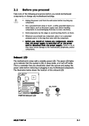
... Standby Power OFF Powered Off ASUS P5MT-M 2-1 This is a reminder that you should shut down the system and unplug the power cable before handling components to avoid damaging them . • Whenever you uninstall any component, place it on a grounded antistatic pad or in any motherboard component. Onboard LED The motherboard comes with the component...
... Standby Power OFF Powered Off ASUS P5MT-M 2-1 This is a reminder that you should shut down the system and unplug the power cable before handling components to avoid damaging them . • Whenever you uninstall any component, place it on a grounded antistatic pad or in any motherboard component. Onboard LED The motherboard comes with the component...

User Manual
Page 22
... the correct orientation. Do not overtighten the screws! Doing so can cause you place it . Refer to the chassis documentation before installing or removing the motherboard. P5MT-M Place this side towards the rear of the chassis ® LAN2 2-2 Chapter 2: Hardware information Failure to do so can damage the...
... the correct orientation. Do not overtighten the screws! Doing so can cause you place it . Refer to the chassis documentation before installing or removing the motherboard. P5MT-M Place this side towards the rear of the chassis ® LAN2 2-2 Chapter 2: Hardware information Failure to do so can damage the...

User Manual
Page 26
... with a surface mount LGA775 socket designed for the CPU and heatsink. Locate the CPU socket on the motherboard. ® LAN2 P5MT-M CPU Socket 775 Before installing the CPU, make sure that the socket box is facing towards you and the load lever is on your... incorrect CPU installation/removal, or misplacement/loss/incorrect removal of the PnP cap. 2.3.1 Installing the CPU To install a CPU: 1. ASUS will process Return Merchandise Authorization (RMA) requests only if the motherboard comes with the cap on the LGA775 socket. • The product warranty does not cover damage to the PnP cap...
... with a surface mount LGA775 socket designed for the CPU and heatsink. Locate the CPU socket on the motherboard. ® LAN2 P5MT-M CPU Socket 775 Before installing the CPU, make sure that the socket box is facing towards you and the load lever is on your... incorrect CPU installation/removal, or misplacement/loss/incorrect removal of the PnP cap. 2.3.1 Installing the CPU To install a CPU: 1. ASUS will process Return Merchandise Authorization (RMA) requests only if the motherboard comes with the cap on the LGA775 socket. • The product warranty does not cover damage to the PnP cap...
User Manual
Page 28
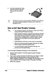
Notes on Intel® Hyper-Threading Technology • This motherboard supports Intel® Pentium® 4 CPUs in the 775-land package with Hyper-Threading Technology. • Hyper-Threading Technology is recommended. • Make sure to ... BIOS to Enabled. DO NOT force the CPU into the retention tab. To use the Hyper-Threading compiler to prevent bending the connectors on this motherboard: 1.
Notes on Intel® Hyper-Threading Technology • This motherboard supports Intel® Pentium® 4 CPUs in the 775-land package with Hyper-Threading Technology. • Hyper-Threading Technology is recommended. • Make sure to ... BIOS to Enabled. DO NOT force the CPU into the retention tab. To use the Hyper-Threading compiler to prevent bending the connectors on this motherboard: 1.

User Manual
Page 29
...assembly, make sure that the four fasteners match the holes on top of the installed CPU, making sure that you have installed the motherboard to the chassis before you install the heatsink and fan assembly. Make sure that the CPU fan cable is closest to orient each ...Motherboard hole Fastener Make sure to the CPU fan connector. To install the CPU heatsink and fan: 1. If you buy a boxed Intel® Pentium® 4 processor, the package includes the CPU fan and heatsink assembly. Narrow end of the groove pointing outward. (The photo shows the groove shaded for emphasis.) ASUS P5MT...
...assembly, make sure that the four fasteners match the holes on top of the installed CPU, making sure that you have installed the motherboard to the chassis before you install the heatsink and fan assembly. Make sure that the CPU fan cable is closest to orient each ...Motherboard hole Fastener Make sure to the CPU fan connector. To install the CPU heatsink and fan: 1. If you buy a boxed Intel® Pentium® 4 processor, the package includes the CPU fan and heatsink assembly. Narrow end of the groove pointing outward. (The photo shows the groove shaded for emphasis.) ASUS P5MT...

User Manual
Page 30
...place. Connect the CPU fan cable to secure the B heatsink and fan assembly in a diagonal sequence to the connector on the motherboard labeled CPU_FAN1/CPU_FAN2. Hardware monitoring errors can occur if you fail to plug this connector. • If there is only one CPU... hardware monitoring errors. 2-10 Chapter 2: Hardware information Failure to the connector labeled CPU_FAN1. A B A B B A 3. CPU_FAN1 CPU_FAN1 P5MT-M FANOUT4 FANPWR2 GND ® LAN2 CPU_FAN2 P5MT-M CPU fan connectors CPU_FAN2 GND FANPWR2 FANOUT4 • Do not forget to connect the CPU fan connector!
...place. Connect the CPU fan cable to secure the B heatsink and fan assembly in a diagonal sequence to the connector on the motherboard labeled CPU_FAN1/CPU_FAN2. Hardware monitoring errors can occur if you fail to plug this connector. • If there is only one CPU... hardware monitoring errors. 2-10 Chapter 2: Hardware information Failure to the connector labeled CPU_FAN1. A B A B B A 3. CPU_FAN1 CPU_FAN1 P5MT-M FANOUT4 FANPWR2 GND ® LAN2 CPU_FAN2 P5MT-M CPU fan connectors CPU_FAN2 GND FANPWR2 FANOUT4 • Do not forget to connect the CPU fan connector!

User Manual
Page 31
Rotate each fastener counterclockwise. 3. A B A B B A ASUS P5MT-M 2-11 Pull up two fasteners at a time in a diagonal sequence to disengage the heatsink B and fan assembly from the connector on the motherboard. 2. Disconnect the CPU fan cable from the A motherboard. 2.3.3 Uninstalling the CPU heatsink and fan To uninstall the CPU heatsink and fan: 1.
Rotate each fastener counterclockwise. 3. A B A B B A ASUS P5MT-M 2-11 Pull up two fasteners at a time in a diagonal sequence to disengage the heatsink B and fan assembly from the connector on the motherboard. 2. Disconnect the CPU fan cable from the A motherboard. 2.3.3 Uninstalling the CPU heatsink and fan To uninstall the CPU heatsink and fan: 1.

User Manual
Page 32
Rotate each fastener clockwise to ensure correct orientation when reinstalling. Carefully remove the heatsink and fan assembly from the motherboard. 5. 4. The narrow end of the groove should point outward after resetting. (The photo shows the groove shaded for emphasis.) Narrow end of the groove 2-12 Chapter 2: Hardware information
Rotate each fastener clockwise to ensure correct orientation when reinstalling. Carefully remove the heatsink and fan assembly from the motherboard. 5. 4. The narrow end of the groove should point outward after resetting. (The photo shows the groove shaded for emphasis.) Narrow end of the groove 2-12 Chapter 2: Hardware information
User Manual
Page 33
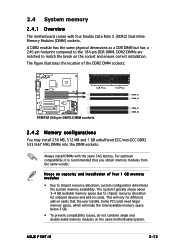
...3 GB. • To prevent compatibility issues, do not combine single and double-sided memory modules on the same motherboard/system. 2.4 System memory 2.4.1 Overview The motherboard comes with the same CAS latency. DDR2 DIMMs are notched to match the break on capacity and installation of the DDR2... need larger memory space, which will vary for onboard devices and add-on cards that you obtain memory modules from the same vendor. ASUS P5MT-M 2-13 For optimum compatibility, it is recommended that the user installs. The figure illustrates the location of four 1 GB memory modules ...
...3 GB. • To prevent compatibility issues, do not combine single and double-sided memory modules on the same motherboard/system. 2.4 System memory 2.4.1 Overview The motherboard comes with the same CAS latency. DDR2 DIMMs are notched to match the break on capacity and installation of the DDR2... need larger memory space, which will vary for onboard devices and add-on cards that you obtain memory modules from the same vendor. ASUS P5MT-M 2-13 For optimum compatibility, it is recommended that the user installs. The figure illustrates the location of four 1 GB memory modules ...
User Manual
Page 35
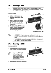
... so can cause severe damage to both the motherboard and the components. Support the DIMM lightly with extra force. 2. 2.4.3 Installing a DIMM Unplug the power supply before adding or removing DIMMs or other system components. Remove the DIMM from the socket. 2 1 DDR2 DIMM notch ASUS P5MT-M 2-15 To install a DIMM: 1. Unlock a DIMM socket by...
... so can cause severe damage to both the motherboard and the components. Support the DIMM lightly with extra force. 2. 2.4.3 Installing a DIMM Unplug the power supply before adding or removing DIMMs or other system components. Remove the DIMM from the socket. 2 1 DDR2 DIMM notch ASUS P5MT-M 2-15 To install a DIMM: 1. Unlock a DIMM socket by...


