
User Manual
Page 3
... About this guide viii P5MT-M specifications summary x Chapter 1: Product introduction 1.1 Welcome 1-1 1.2 Package contents 1-1 1.3 Special features 1-2 1.3.1 Product highlights 1-2 1.3.2 Innovative ASUS features 1-4 Chapter 2: Hardware information 2.1 Before you proceed 2-1 2.2 Motherboard overview 2-2 2.2.1 Placement direction 2-2 2.2.2 Screw holes 2-2 2.2.3 Motherboard layout 2-3 2.2.4 Layout contents 2-4 2.3 Central Processing Unit (CPU 2-6 2.3.1 Installing the CPU 2-6 2.3.2 Installing the CPU heatsink and fan 2-9 2.3.3 Uninstalling the CPU heatsink and fan 2-11...
... About this guide viii P5MT-M specifications summary x Chapter 1: Product introduction 1.1 Welcome 1-1 1.2 Package contents 1-1 1.3 Special features 1-2 1.3.1 Product highlights 1-2 1.3.2 Innovative ASUS features 1-4 Chapter 2: Hardware information 2.1 Before you proceed 2-1 2.2 Motherboard overview 2-2 2.2.1 Placement direction 2-2 2.2.2 Screw holes 2-2 2.2.3 Motherboard layout 2-3 2.2.4 Layout contents 2-4 2.3 Central Processing Unit (CPU 2-6 2.3.1 Installing the CPU 2-6 2.3.2 Installing the CPU heatsink and fan 2-9 2.3.3 Uninstalling the CPU heatsink and fan 2-11...

User Manual
Page 4
... power switch 3-2 Chapter 4: BIOS setup 4.1 Managing and updating your BIOS 4-1 4.1.1 Creating a bootable floppy disk 4-1 4.1.2 ASUS EZ Flash utility 4-2 4.1.3 AFUDOS utility 4-3 4.1.4 ASUS CrashFree BIOS 2 utility 4-6 4.1.5 ASUS Update utility 4-8 4.2 BIOS setup program 4-11 4.2.1 BIOS menu screen 4-12 4.2.2 Menu bar 4-12 4.2.3 Navigation keys 4-... 4.4 Advanced menu 4-19 4.4.1 USB Configuration 4-19 4.4.2 MPS Configuration 4-20 4.4.3 Remote Access Configuration 4-21 4.4.4 CPU Configuration 4-22 4.4.5 Chipset 4-23 4.4.6 Onboard Devices Configuration 4-25 4.4.7 PCI PnP 4-26 iv
... power switch 3-2 Chapter 4: BIOS setup 4.1 Managing and updating your BIOS 4-1 4.1.1 Creating a bootable floppy disk 4-1 4.1.2 ASUS EZ Flash utility 4-2 4.1.3 AFUDOS utility 4-3 4.1.4 ASUS CrashFree BIOS 2 utility 4-6 4.1.5 ASUS Update utility 4-8 4.2 BIOS setup program 4-11 4.2.1 BIOS menu screen 4-12 4.2.2 Menu bar 4-12 4.2.3 Navigation keys 4-... 4.4 Advanced menu 4-19 4.4.1 USB Configuration 4-19 4.4.2 MPS Configuration 4-20 4.4.3 Remote Access Configuration 4-21 4.4.4 CPU Configuration 4-22 4.4.5 Chipset 4-23 4.4.6 Onboard Devices Configuration 4-25 4.4.7 PCI PnP 4-26 iv
User Manual
Page 10
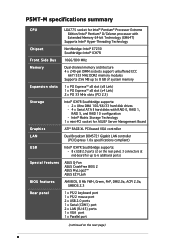
...; ICH7R Southbridge supports: - 8 x USB 2.0 ports (2 on the next page) x P5MT-M specifications summary CPU Chipset Front Side Bus Memory Expansion slots Storage Graphics LAN USB Special features BIOS features Rear panel LGA775 socket for up to 6 additional ports) ASUS Q-Fan ASUS CrashFree BIOS 2 ASUS MyLogo2™ ASUS EZ FLash AMI BIOS, 8 Mb FWH, Green, PnP, DMI2.0a...
...; ICH7R Southbridge supports: - 8 x USB 2.0 ports (2 on the next page) x P5MT-M specifications summary CPU Chipset Front Side Bus Memory Expansion slots Storage Graphics LAN USB Special features BIOS features Rear panel LGA775 socket for up to 6 additional ports) ASUS Q-Fan ASUS CrashFree BIOS 2 ASUS MyLogo2™ ASUS EZ FLash AMI BIOS, 8 Mb FWH, Green, PnP, DMI2.0a...
User Manual
Page 11
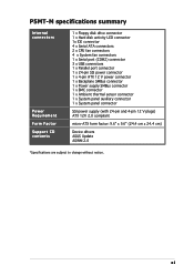
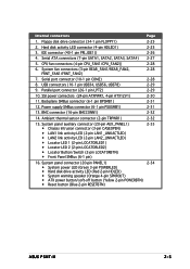
P5MT-M specifications summary Internal connectors Power Requirement Form Factor Support CD contents 1 x Floppy disk drive connector 1 x Hard disk activity LED connector 1x IDE connector 4 x Serial ATA connectors 2 x CPU fan connectors 4 x System fan connectors 1 x Serial port (COM2) connector 3 x USB connectors 1 x Parallel port connector 1 x 24-pin SSI power connector 1 x 4-pin ATX 12 ...(with 24-pin and 4-pin 12 V plugs) ATX 12V 2.0 compliant micro-ATX form factor: 9.6" x 9.6" (24.4 cm x 24.4 cm) Device drivers ASUS Update ASWM 2.0 *Specifications are subject to change without notice. xi
P5MT-M specifications summary Internal connectors Power Requirement Form Factor Support CD contents 1 x Floppy disk drive connector 1 x Hard disk activity LED connector 1x IDE connector 4 x Serial ATA connectors 2 x CPU fan connectors 4 x System fan connectors 1 x Serial port (COM2) connector 3 x USB connectors 1 x Parallel port connector 1 x 24-pin SSI power connector 1 x 4-pin ATX 12 ...(with 24-pin and 4-pin 12 V plugs) ATX 12V 2.0 compliant micro-ATX form factor: 9.6" x 9.6" (24.4 cm x 24.4 cm) Device drivers ASUS Update ASWM 2.0 *Specifications are subject to change without notice. xi
User Manual
Page 20
Chapter summary 2 2.1 Before you proceed 2-1 2.2 Motherboard overview 2-2 2.3 Central Processing Unit (CPU 2-6 2.4 System memory 2-13 2.5 Expansion slots 2-16 2.6 Jumpers 2-19 2.7 Connectors 2-24 ASUS P5MT-M
Chapter summary 2 2.1 Before you proceed 2-1 2.2 Motherboard overview 2-2 2.3 Central Processing Unit (CPU 2-6 2.4 System memory 2-13 2.5 Expansion slots 2-16 2.6 Jumpers 2-19 2.7 Connectors 2-24 ASUS P5MT-M

User Manual
Page 24
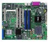
CPU fan pin selection (3-pin FM_CPU1, FM_CPU2) 3. BIOS recovery (3-pin RECOVERY1) 9. LAN 2 (RJ-45) port Page 2-24 2-24 2-24 2-24 2-24 2-24 2-24 2-24 2-4 Chapter 2: Hardware ... 2-6 2-13 2-18 Jumpers 1. Gigabit LAN controller setting (3-pin LAN_EN1) 6. PS/2 mouse port (green) 2. USB 2.0 ports 1 and 2 5. Serial (COM1) port 6. VGA port 7. PS/2 keyboard port (purple) 4. CPU sockets 2. DDR2 DIMM sockets 3. Clear RTC RAM (CLRTC1) 2. Keyboard power (3-pin KBPWR1) 5. RAID select (3-pin RAID_SEL1) Page 2-19 2-20 2-20 2-21 2-21 2-22 2-22 2-23...
CPU fan pin selection (3-pin FM_CPU1, FM_CPU2) 3. BIOS recovery (3-pin RECOVERY1) 9. LAN 2 (RJ-45) port Page 2-24 2-24 2-24 2-24 2-24 2-24 2-24 2-24 2-4 Chapter 2: Hardware ... 2-6 2-13 2-18 Jumpers 1. Gigabit LAN controller setting (3-pin LAN_EN1) 6. PS/2 mouse port (green) 2. USB 2.0 ports 1 and 2 5. Serial (COM1) port 6. VGA port 7. PS/2 keyboard port (purple) 4. CPU sockets 2. DDR2 DIMM sockets 3. Clear RTC RAM (CLRTC1) 2. Keyboard power (3-pin KBPWR1) 5. RAID select (3-pin RAID_SEL1) Page 2-19 2-20 2-20 2-21 2-21 2-22 2-22 2-23...
User Manual
Page 25
...4-pin SPKROUT) • ATX power button/soft-off button (Yellow 2-pin POWERBTN) • Reset button (Blue 2-pin RESETBTN) 2-34 ASUS P5MT-M 2-5 Power supply SMBus connector (6-1 pin PSUSMB1) 2-31 13. System panel auxiliary connector (20-pin AUX_PANEL1) • Chassis Intrusion connector (3-... connector (16-pin BMCCONN1) 2-32 14. Internal connectors Page 1. SSI power connectors (24-pin ATXPWR1, 4-pin ATX12V1) 2-30 11. CPU fan connectors (4-pin CPU_FAN1/CPU_FAN2)) 2-28 6. Ambient thermal sensor connector (2-pin TRPWR1) 2-32 15. Parallel port connector (26-1 pin LPT2...
...4-pin SPKROUT) • ATX power button/soft-off button (Yellow 2-pin POWERBTN) • Reset button (Blue 2-pin RESETBTN) 2-34 ASUS P5MT-M 2-5 Power supply SMBus connector (6-1 pin PSUSMB1) 2-31 13. System panel auxiliary connector (20-pin AUX_PANEL1) • Chassis Intrusion connector (3-... connector (16-pin BMCCONN1) 2-32 14. Internal connectors Page 1. SSI power connectors (24-pin ATXPWR1, 4-pin ATX12V1) 2-30 11. CPU fan connectors (4-pin CPU_FAN1/CPU_FAN2)) 2-28 6. Ambient thermal sensor connector (2-pin TRPWR1) 2-32 15. Parallel port connector (26-1 pin LPT2...

User Manual
Page 26
...P5MT-M CPU Socket 775 Before installing the CPU, make sure that the socket box is facing towards you see any damage to the socket contacts resulting from incorrect CPU installation/removal, or misplacement/loss/incorrect removal of the PnP cap. 2.3.1 Installing the CPU To install a CPU: 1. ASUS...not bent. Contact your left. ASUS will process Return Merchandise Authorization (RMA) requests only if the motherboard comes with installation instructions for the CPU and heatsink. P5MT-M 2-6 Chapter 2: Hardware information 2.3 Central Processing Unit (CPU) The motherboard comes with a ...
...P5MT-M CPU Socket 775 Before installing the CPU, make sure that the socket box is facing towards you see any damage to the socket contacts resulting from incorrect CPU installation/removal, or misplacement/loss/incorrect removal of the PnP cap. 2.3.1 Installing the CPU To install a CPU: 1. ASUS...not bent. Contact your left. ASUS will process Return Merchandise Authorization (RMA) requests only if the motherboard comes with installation instructions for the CPU and heatsink. P5MT-M 2-6 Chapter 2: Hardware information 2.3 Central Processing Unit (CPU) The motherboard comes with a ...
User Manual
Page 27
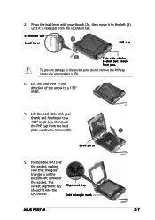
...socket pins, do not remove the PnP cap unless you . The socket alignment key A l i g n m e n t k e y should face you are installing a CPU. 3. Position the CPU over the socket, making sure that the gold triangle is on the bottom-left (B) until it is released from the load plate window to the... with your thumb and forefinger to a 135º angle. 4. 2. Lift the load lever in the direction of the socket box should fit into the CPU notch. Load plate 5. Retention tab A Load lever PnP cap B This side of the arrow to a B 100º angle (A), then push the...
...socket pins, do not remove the PnP cap unless you . The socket alignment key A l i g n m e n t k e y should face you are installing a CPU. 3. Position the CPU over the socket, making sure that the gold triangle is on the bottom-left (B) until it is released from the load plate window to the... with your thumb and forefinger to a 135º angle. 4. 2. Lift the load lever in the direction of the socket box should fit into the CPU notch. Load plate 5. Retention tab A Load lever PnP cap B This side of the arrow to a B 100º angle (A), then push the...
User Manual
Page 28
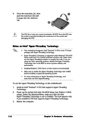
...Hyper-Threading Technology, visit www.intel.com/info/hyperthreading. Reboot the computer. 2-8 Chapter 2: Hardware information DO NOT force the CPU into the retention tab. The item appears only if you are using any other operating systems, disable the Hyper-Threading Technology ...supported under Windows® XP/2003 Server and Linux 2.4.x (kernel) and later versions only. If you installed a CPU that supports Hyper-Threading Technology. 2. 6. B The CPU fits in the 775-land package with Hyper-Threading Technology. • Hyper-Threading Technology is recommended. • ...
...Hyper-Threading Technology, visit www.intel.com/info/hyperthreading. Reboot the computer. 2-8 Chapter 2: Hardware information DO NOT force the CPU into the retention tab. The item appears only if you are using any other operating systems, disable the Hyper-Threading Technology ...supported under Windows® XP/2003 Server and Linux 2.4.x (kernel) and later versions only. If you installed a CPU that supports Hyper-Threading Technology. 2. 6. B The CPU fits in the 775-land package with Hyper-Threading Technology. • Hyper-Threading Technology is recommended. • ...

User Manual
Page 29
... match the holes on top of the groove pointing outward. (The photo shows the groove shaded for emphasis.) ASUS P5MT-M 2-9 Place the heatsink on the motherboard. To install the CPU heatsink and fan: 1. 2.3.2 Installing the CPU heatsink and fan The Intel® Pentium® 4 LGA775 processor requires a specially designed heatsink and fan assembly to...
... match the holes on top of the groove pointing outward. (The photo shows the groove shaded for emphasis.) ASUS P5MT-M 2-9 Place the heatsink on the motherboard. To install the CPU heatsink and fan: 1. 2.3.2 Installing the CPU heatsink and fan The Intel® Pentium® 4 LGA775 processor requires a specially designed heatsink and fan assembly to...

User Manual
Page 30
... in A place. 2. Push down two fasteners at a time in a diagonal sequence to the connector on the motherboard labeled CPU_FAN1/CPU_FAN2. CPU_FAN1 CPU_FAN1 P5MT-M FANOUT4 FANPWR2 GND ® LAN2 CPU_FAN2 P5MT-M CPU fan connectors CPU_FAN2 GND FANPWR2 FANOUT4 • Do not forget to the connector labeled CPU_FAN1. Hardware monitoring errors can occur if you...
... in A place. 2. Push down two fasteners at a time in a diagonal sequence to the connector on the motherboard labeled CPU_FAN1/CPU_FAN2. CPU_FAN1 CPU_FAN1 P5MT-M FANOUT4 FANPWR2 GND ® LAN2 CPU_FAN2 P5MT-M CPU fan connectors CPU_FAN2 GND FANPWR2 FANOUT4 • Do not forget to the connector labeled CPU_FAN1. Hardware monitoring errors can occur if you...

User Manual
Page 31
Disconnect the CPU fan cable from the A motherboard. Pull up two fasteners at a time in a diagonal sequence to disengage the heatsink B and fan assembly from the connector on the motherboard. 2. 2.3.3 Uninstalling the CPU heatsink and fan To uninstall the CPU heatsink and fan: 1. A B A B B A ASUS P5MT-M 2-11 Rotate each fastener counterclockwise. 3.
Disconnect the CPU fan cable from the A motherboard. Pull up two fasteners at a time in a diagonal sequence to disengage the heatsink B and fan assembly from the connector on the motherboard. 2. 2.3.3 Uninstalling the CPU heatsink and fan To uninstall the CPU heatsink and fan: 1. A B A B B A ASUS P5MT-M 2-11 Rotate each fastener counterclockwise. 3.

User Manual
Page 40
... pins 2-3 if you are using a 3-pin fan cable plug, or to wake up from S1 sleep mode (CPU stopped, DRAM refreshed, system running in low power mode) using a 4-pin plug. ® LAN2 P5MT-M FM CPU Setting P5MT-M FM_CPU1 1 2 3-pin fan (Default) 2 3 4-pin fan FM_CPU2 12 23 3-pin fan 4-pin fan (... up the computer from S4 sleep mode (no power to the CPU fan connectors (CPU_FAN1, CPU_FAN2). CPU fan pin selection (3-pin FM_CPU1, FM_CPU2) These jumpers allow you are using the connected USB devices. P5MT-M ® LAN2 P5MT-M USB device wake-up 32 USBPW12 +5VSB 32 USBPW78 +5VSB 32...
... pins 2-3 if you are using a 3-pin fan cable plug, or to wake up from S1 sleep mode (CPU stopped, DRAM refreshed, system running in low power mode) using a 4-pin plug. ® LAN2 P5MT-M FM CPU Setting P5MT-M FM_CPU1 1 2 3-pin fan (Default) 2 3 4-pin fan FM_CPU2 12 23 3-pin fan 4-pin fan (... up the computer from S4 sleep mode (no power to the CPU fan connectors (CPU_FAN1, CPU_FAN2). CPU fan pin selection (3-pin FM_CPU1, FM_CPU2) These jumpers allow you are using the connected USB devices. P5MT-M ® LAN2 P5MT-M USB device wake-up 32 USBPW12 +5VSB 32 USBPW78 +5VSB 32...

User Manual
Page 48
... port2 (COM2) connector 2-28 Chapter 2: Hardware information CPU_FAN1 P5MT-M ® LAN2 REAR_FAN2 CPU_FAN2 FRNT_FAN1 FRNT_FAN2 REAR_FAN1 P5MT-M Fan connectors CPU_FAN1 CPU_FAN2 GND FANPWR3 FANOUT7 FANOUT4 FANPWR2 GND FRNT_FAN1 FRNT_FAN2 GND +12V Rotation GND +12V Rotation REAR_FAN1 REAR_FAN2 Rotation +12V GND Rotation +12V GND 6 . CPU and system fan connectors (4-pin CPU_FAN1/2, 3-pin REAR_FAN1/2, 3-pin...
... port2 (COM2) connector 2-28 Chapter 2: Hardware information CPU_FAN1 P5MT-M ® LAN2 REAR_FAN2 CPU_FAN2 FRNT_FAN1 FRNT_FAN2 REAR_FAN1 P5MT-M Fan connectors CPU_FAN1 CPU_FAN2 GND FANPWR3 FANOUT7 FANOUT4 FANPWR2 GND FRNT_FAN1 FRNT_FAN2 GND +12V Rotation GND +12V Rotation REAR_FAN1 REAR_FAN2 Rotation +12V GND Rotation +12V GND 6 . CPU and system fan connectors (4-pin CPU_FAN1/2, 3-pin REAR_FAN1/2, 3-pin...

User Manual
Page 78
Processor Displays the auto-detected CPU specification. 4.3.6 System Information This menu gives you an overview of the general system specifications. AMIBIOS Version : 08.00.11 Build Date : 03/21/05 Processor Type : Genuine Intel(R) CPU 3.20 GHz Speed : 3200 MHz Count : 1 System Memory Size : 512 MB AMI BIOS Displays the auto-detected BIOS information. The BIOS automatically detects the items in this menu. System Memory Displays the auto-detected system memory. 4-18 Chapter 4: BIOS setup
Processor Displays the auto-detected CPU specification. 4.3.6 System Information This menu gives you an overview of the general system specifications. AMIBIOS Version : 08.00.11 Build Date : 03/21/05 Processor Type : Genuine Intel(R) CPU 3.20 GHz Speed : 3200 MHz Count : 1 System Memory Size : 512 MB AMI BIOS Displays the auto-detected BIOS information. The BIOS automatically detects the items in this menu. System Memory Displays the auto-detected system memory. 4-18 Chapter 4: BIOS setup

User Manual
Page 79
... u l e V e r s i o n and U S B D e v i c e s E n a b l e d items show the auto-detected values. Select an item then press to malfunction. ASUS P5MT-M 4-19 USB Configuration MPS Configuration Remote Access Configuration CPU Configuration Chipset Onboard Devices Configuration PCI PnP USB settings. 4.4.1 USB Configuration The items in this menu allow you to change the... settings for the CPU and other system devices. Take caution when changing the settings of the Advanced menu items. Incorrect field ...
... u l e V e r s i o n and U S B D e v i c e s E n a b l e d items show the auto-detected values. Select an item then press to malfunction. ASUS P5MT-M 4-19 USB Configuration MPS Configuration Remote Access Configuration CPU Configuration Chipset Onboard Devices Configuration PCI PnP USB settings. 4.4.1 USB Configuration The items in this menu allow you to change the... settings for the CPU and other system devices. Take caution when changing the settings of the Advanced menu items. Incorrect field ...

User Manual
Page 82
... or disable the execute disable function. Configuration options: [Disabled] [Enabled] 4-22 Chapter 4: BIOS setup Configure advanced CPU Settings Manufacturer : Intel Brand String : Genuine Intel (R) CPU 3.20GHz Frequency : 3200 MHz FSB Speed : 800 MHz Cache L1 Cache L2 Cache L3 : 16 KB : ...Enhanced C1 Control [Auto] Hardware Prefetcher: [Enabled] Adjacent Cache Line Prefetch: [Enabled] CPU Internal Thermal Control [Auto] Hyper Threading Technology [Enabled] Sets the ratio between CPU Core Clock and the FSB Frequency. VT-UTF8 Combo Key Support [Enabled] Enables or disables...
... or disable the execute disable function. Configuration options: [Disabled] [Enabled] 4-22 Chapter 4: BIOS setup Configure advanced CPU Settings Manufacturer : Intel Brand String : Genuine Intel (R) CPU 3.20GHz Frequency : 3200 MHz FSB Speed : 800 MHz Cache L1 Cache L2 Cache L3 : 16 KB : ...Enhanced C1 Control [Auto] Hardware Prefetcher: [Enabled] Adjacent Cache Line Prefetch: [Enabled] CPU Internal Thermal Control [Auto] Hyper Threading Technology [Enabled] Sets the ratio between CPU Core Clock and the FSB Frequency. VT-UTF8 Combo Key Support [Enabled] Enables or disables...

User Manual
Page 83
...] Allows you to display the sub-menu. Select an item then press to change the advanced chipset settings. Configuration options: [Auto] [533 MHz] [667 MHz] ASUS P5MT-M 4-23 Configuration options: [Disabled] [Enabled] CPU Internal Thermal Control [Auto] Disables or sets the...
...] Allows you to display the sub-menu. Select an item then press to change the advanced chipset settings. Configuration options: [Auto] [533 MHz] [667 MHz] ASUS P5MT-M 4-23 Configuration options: [Disabled] [Enabled] CPU Internal Thermal Control [Auto] Disables or sets the...

User Manual
Page 89
... feature requires an ATX power supply that appears below shows the default N o t I n s t a l l e d. 4.5.3 Hardware Monitor Hardware Monitor CPU Temperature MB Temperature CPU1 Fan Speed CPU2 Fan Speed Front Fan1 Speed Front Fan2 Speed Rear Fan1 Speed Rear Fan2 Speed Smart Fan Control VCORE1...ºC/xxxºF] MB Temperature [xxxºC/xxxºF] The onboard hardware monitor automatically detects and displays the motherboard, CPU, and ambient temperatures. ASUS P5MT-M 4-29 Configuration options: [Disabled] [Enabled] Keyboard Wakeup Password This item appears only when the Power On By PS...
... feature requires an ATX power supply that appears below shows the default N o t I n s t a l l e d. 4.5.3 Hardware Monitor Hardware Monitor CPU Temperature MB Temperature CPU1 Fan Speed CPU2 Fan Speed Front Fan1 Speed Front Fan2 Speed Rear Fan1 Speed Rear Fan2 Speed Smart Fan Control VCORE1...ºC/xxxºF] MB Temperature [xxxºC/xxxºF] The onboard hardware monitor automatically detects and displays the motherboard, CPU, and ambient temperatures. ASUS P5MT-M 4-29 Configuration options: [Disabled] [Enabled] Keyboard Wakeup Password This item appears only when the Power On By PS...


