
User Manual
Page 1
P5MT-M Motherboard
P5MT-M Motherboard

User Manual
Page 3
Contents Notices vi Safety information vii About this guide viii P5MT-M specifications summary x Chapter 1: Product introduction 1.1 Welcome 1-1 1.2 Package contents 1-1 1.3 Special features 1-2 1.3.1 Product highlights 1-2 1.3.2 Innovative ASUS features 1-4 Chapter 2: Hardware information 2.1 Before you proceed 2-1 2.2 Motherboard overview 2-2 2.2.1 Placement direction 2-2 2.2.2 Screw holes 2-2 2.2.3 Motherboard layout 2-3 2.2.4 Layout contents 2-4 2.3 Central Processing Unit (CPU 2-6 2.3.1 Installing the CPU 2-6 2.3.2 Installing the CPU heatsink and fan...
Contents Notices vi Safety information vii About this guide viii P5MT-M specifications summary x Chapter 1: Product introduction 1.1 Welcome 1-1 1.2 Package contents 1-1 1.3 Special features 1-2 1.3.1 Product highlights 1-2 1.3.2 Innovative ASUS features 1-4 Chapter 2: Hardware information 2.1 Before you proceed 2-1 2.2 Motherboard overview 2-2 2.2.1 Placement direction 2-2 2.2.2 Screw holes 2-2 2.2.3 Motherboard layout 2-3 2.2.4 Layout contents 2-4 2.3 Central Processing Unit (CPU 2-6 2.3.1 Installing the CPU 2-6 2.3.2 Installing the CPU heatsink and fan...

User Manual
Page 7
...disconnect the power cable from the electrical outlet before relocating the system. • When adding or removing devices to or from the motherboard, ensure that all power cables are unplugged. • Seek professional assistance before the signal cables are not damaged. If possible, ...ensure that the power cables for the devices are unplugged before using an adapter or extension cord. Operation safety • Before installing the motherboard and adding devices on a stable surface. • If you detect any damage, contact your retailer. These devices could interrupt the grounding...
...disconnect the power cable from the electrical outlet before relocating the system. • When adding or removing devices to or from the motherboard, ensure that all power cables are unplugged. • Seek professional assistance before the signal cables are not damaged. If possible, ...ensure that the power cables for the devices are unplugged before using an adapter or extension cord. Operation safety • Before installing the motherboard and adding devices on a stable surface. • If you detect any damage, contact your retailer. These devices could interrupt the grounding...
User Manual
Page 8
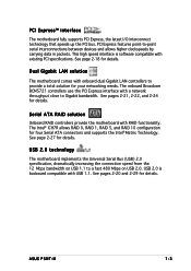
.... These documents are also provided. • Chapter 5: RAID support Provides information on RAID configurations for this motherboard. • Chapter 6: Driver installation This chapter provides information on ASUS hardware and software products. viii Refer to the ASUS contact information. 2. About this guide This user guide contains the information you may refer to when configuring...
.... These documents are also provided. • Chapter 5: RAID support Provides information on RAID configurations for this motherboard. • Chapter 6: Driver installation This chapter provides information on ASUS hardware and software products. viii Refer to the ASUS contact information. 2. About this guide This user guide contains the information you may refer to when configuring...

User Manual
Page 13
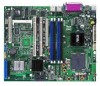
This chapter describes the motherboard features and the new technologies it supports. 1Product introduction
This chapter describes the motherboard features and the new technologies it supports. 1Product introduction
User Manual
Page 15
... you for the following items. Motherboard ASUS P5MT-M motherboard Cables Accessories Application CD Documentation 2-in the long line of the above items is damaged or missing, contact your retailer. Thank you start installing the motherboard, and hardware devices on it another standout in -1 disk drive ...x Serial ATA signal cables 2 x Serial ATA power cable 1 x USB PCI cable bracket I/O shield ASUS motherboard support CD User guide If any of ASUS quality motherboards! The motherboard delivers a host of new features and latest technologies, making it , check the items in your package ...
... you for the following items. Motherboard ASUS P5MT-M motherboard Cables Accessories Application CD Documentation 2-in the long line of the above items is damaged or missing, contact your retailer. Thank you start installing the motherboard, and hardware devices on it another standout in -1 disk drive ...x Serial ATA signal cables 2 x Serial ATA power cable 1 x USB PCI cable bracket I/O shield ASUS motherboard support CD User guide If any of ASUS quality motherboards! The motherboard delivers a host of new features and latest technologies, making it , check the items in your package ...

User Manual
Page 16
...Threading technology and incorporates the Extended Memory 64-bit Technology (EM64T). The SATA II specification allows for details. DDR2 memory support The motherboard supports DDR2 memory, which features data transfer rates of 667 MHz or 533 MHz to 10.7 GB/s. See page 2-13 for details...interfaces controlled by the Intel® ICH7R. See page 2-27 for details. 1.3 Special features 1.3.1 Product highlights Latest processor technology The motherboard comes with a 775-pin surface mount Land Grid Array (LGA) socket designed for the Intel® Pentium® Processor Extreme ...
...Threading technology and incorporates the Extended Memory 64-bit Technology (EM64T). The SATA II specification allows for details. DDR2 memory support The motherboard supports DDR2 memory, which features data transfer rates of 667 MHz or 533 MHz to 10.7 GB/s. See page 2-13 for details...interfaces controlled by the Intel® ICH7R. See page 2-27 for details. 1.3 Special features 1.3.1 Product highlights Latest processor technology The motherboard comes with a 775-pin surface mount Land Grid Array (LGA) socket designed for the Intel® Pentium® Processor Extreme ...
User Manual
Page 17
...PCI Express, the latest I/O interconnect technology that speeds up the PCI bus. Dual Gigabit LAN solution The motherboard comes with onboard dual Gigabit LAN controllers to Gigabit bandwidth. The onboard Broadcom BCM5721 controllers use the PCI...carrying data in packets. USB 2.0 technology The motherboard implements the Universal Serial Bus (USB) 2.0 specification, dramatically increasing the connection speed from the 12 Mbps bandwidth on USB 2.0. ASUS P5MT-M 1-3 Serial ATA RAID solution Onboard RAID controllers provide the motherboard with a network throughput close to provide a ...
...PCI Express, the latest I/O interconnect technology that speeds up the PCI bus. Dual Gigabit LAN solution The motherboard comes with onboard dual Gigabit LAN controllers to Gigabit bandwidth. The onboard Broadcom BCM5721 controllers use the PCI...carrying data in packets. USB 2.0 technology The motherboard implements the Universal Serial Bus (USB) 2.0 specification, dramatically increasing the connection speed from the 12 Mbps bandwidth on USB 2.0. ASUS P5MT-M 1-3 Serial ATA RAID solution Onboard RAID controllers provide the motherboard with a network throughput close to provide a ...

User Manual
Page 19
This chapter lists the hardware setup procedures that you have to perform when installing system components. It includes description of the jumpers and connectors on the motherboard. 2 Hardware information
This chapter lists the hardware setup procedures that you have to perform when installing system components. It includes description of the jumpers and connectors on the motherboard. 2 Hardware information
User Manual
Page 20
Chapter summary 2 2.1 Before you proceed 2-1 2.2 Motherboard overview 2-2 2.3 Central Processing Unit (CPU 2-6 2.4 System memory 2-13 2.5 Expansion slots 2-16 2.6 Jumpers 2-19 2.7 Connectors 2-24 ASUS P5MT-M
Chapter summary 2 2.1 Before you proceed 2-1 2.2 Motherboard overview 2-2 2.3 Central Processing Unit (CPU 2-6 2.4 System memory 2-13 2.5 Expansion slots 2-16 2.6 Jumpers 2-19 2.7 Connectors 2-24 ASUS P5MT-M
User Manual
Page 21
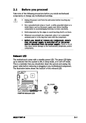
... off mode. P5MT-M ® LAN2 P5MT-M Onboard LED SB_PWR1 ON Standby Power OFF Powered Off ASUS P5MT-M 2-1 2.1 Before you proceed Take note of the onboard LED. The illustration below shows the location of the following precautions before you install motherboard components or change any motherboard settings. •...wrist strap or touch a safely grounded object or a metal object, such as the power supply case, before removing or plugging in any motherboard component. This is a reminder that the power supply is ON, in sleep mode, or in the bag that came with a standby power...
... off mode. P5MT-M ® LAN2 P5MT-M Onboard LED SB_PWR1 ON Standby Power OFF Powered Off ASUS P5MT-M 2-1 2.1 Before you proceed Take note of the onboard LED. The illustration below shows the location of the following precautions before you install motherboard components or change any motherboard settings. •...wrist strap or touch a safely grounded object or a metal object, such as the power supply case, before removing or plugging in any motherboard component. This is a reminder that the power supply is ON, in sleep mode, or in the bag that came with a standby power...

User Manual
Page 22
P5MT-M Place this side towards the rear of the chassis ® LAN2 2-2 Chapter 2: Hardware information Failure to the chassis documentation before installing or removing the motherboard. Refer to do so can damage the motherboard. Make sure to the chassis. The edge with external ports goes to the rear part of the chassis as indicated...
P5MT-M Place this side towards the rear of the chassis ® LAN2 2-2 Chapter 2: Hardware information Failure to the chassis documentation before installing or removing the motherboard. Refer to do so can damage the motherboard. Make sure to the chassis. The edge with external ports goes to the rear part of the chassis as indicated...

User Manual
Page 26
... the damage is on the motherboard. ® LAN2 P5MT-M CPU Socket 775 Before installing the CPU, make sure that the socket box is on the LGA775 socket. • The product warranty does not cover damage to the PnP cap/socket contacts/motherboard components. ASUS will shoulder the cost of the motherboard, make sure that the...
... the damage is on the motherboard. ® LAN2 P5MT-M CPU Socket 775 Before installing the CPU, make sure that the socket box is on the LGA775 socket. • The product warranty does not cover damage to the PnP cap/socket contacts/motherboard components. ASUS will shoulder the cost of the motherboard, make sure that the...
User Manual
Page 28
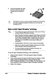
.... • Installing Windows® 2003 Server or later version is recommended. • Make sure to prevent bending the connectors on this motherboard: 1. If you installed a CPU that supports Hyper-Threading Technology. 3. Under the Advanced Menu, make sure that supports Hyper-Threading Technology.... in BIOS before installing a supported operating system. • For more information on Intel® Hyper-Threading Technology • This motherboard supports Intel® Pentium® 4 CPUs in only one correct orientation. Under Linux, use the Hyper-Threading Technology on the...
.... • Installing Windows® 2003 Server or later version is recommended. • Make sure to prevent bending the connectors on this motherboard: 1. If you installed a CPU that supports Hyper-Threading Technology. 3. Under the Advanced Menu, make sure that supports Hyper-Threading Technology.... in BIOS before installing a supported operating system. • For more information on Intel® Hyper-Threading Technology • This motherboard supports Intel® Pentium® 4 CPUs in only one correct orientation. Under Linux, use the Hyper-Threading Technology on the...

User Manual
Page 29
...and fan assembly to orient each fastener with the narrow end of the groove pointing outward. (The photo shows the groove shaded for emphasis.) ASUS P5MT-M 2-9 Make sure that you have properly applied Thermal Interface Material to the CPU heatsink or CPU before you buy a CPU separately, make sure... you purchased a separate CPU heatsink and fan assembly, make sure that you install the heatsink and fan assembly. Place the heatsink on the motherboard. Orient the heatsink and fan assembly such that the four fasteners match the holes on top of the installed CPU, making sure that the CPU...
...and fan assembly to orient each fastener with the narrow end of the groove pointing outward. (The photo shows the groove shaded for emphasis.) ASUS P5MT-M 2-9 Make sure that you have properly applied Thermal Interface Material to the CPU heatsink or CPU before you buy a CPU separately, make sure... you purchased a separate CPU heatsink and fan assembly, make sure that you install the heatsink and fan assembly. Place the heatsink on the motherboard. Orient the heatsink and fan assembly such that the four fasteners match the holes on top of the installed CPU, making sure that the CPU...

User Manual
Page 30
... FANPWR2 GND ® LAN2 CPU_FAN2 P5MT-M CPU fan connectors CPU_FAN2 GND FANPWR2 FANOUT4 • Do not forget to secure the B heatsink and fan assembly in a diagonal sequence to connect the CPU ... cable, connect it to do so may cause hardware monitoring errors. 2-10 Chapter 2: Hardware information Connect the CPU fan cable to the connector on the motherboard labeled CPU_FAN1/CPU_FAN2. 2. A B A B B A 3.
... FANPWR2 GND ® LAN2 CPU_FAN2 P5MT-M CPU fan connectors CPU_FAN2 GND FANPWR2 FANOUT4 • Do not forget to secure the B heatsink and fan assembly in a diagonal sequence to connect the CPU ... cable, connect it to do so may cause hardware monitoring errors. 2-10 Chapter 2: Hardware information Connect the CPU fan cable to the connector on the motherboard labeled CPU_FAN1/CPU_FAN2. 2. A B A B B A 3.

User Manual
Page 31
Rotate each fastener counterclockwise. 3. Disconnect the CPU fan cable from the A motherboard. Pull up two fasteners at a time in a diagonal sequence to disengage the heatsink B and fan assembly from the connector on the motherboard. 2. A B A B B A ASUS P5MT-M 2-11 2.3.3 Uninstalling the CPU heatsink and fan To uninstall the CPU heatsink and fan: 1.
Rotate each fastener counterclockwise. 3. Disconnect the CPU fan cable from the A motherboard. Pull up two fasteners at a time in a diagonal sequence to disengage the heatsink B and fan assembly from the connector on the motherboard. 2. A B A B B A ASUS P5MT-M 2-11 2.3.3 Uninstalling the CPU heatsink and fan To uninstall the CPU heatsink and fan: 1.

User Manual
Page 32
Rotate each fastener clockwise to ensure correct orientation when reinstalling. The narrow end of the groove should point outward after resetting. (The photo shows the groove shaded for emphasis.) Narrow end of the groove 2-12 Chapter 2: Hardware information Carefully remove the heatsink and fan assembly from the motherboard. 5. 4.
Rotate each fastener clockwise to ensure correct orientation when reinstalling. The narrow end of the groove should point outward after resetting. (The photo shows the groove shaded for emphasis.) Narrow end of the groove 2-12 Chapter 2: Hardware information Carefully remove the heatsink and fan assembly from the motherboard. 5. 4.
User Manual
Page 33
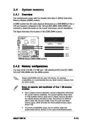
...to match the break on the same motherboard/system. Some PCI cards need larger memory space, which will vary for onboard devices and add-on capacity and installation of the DDR2 DIMM sockets: P5MT-M ® LAN2 128 Pins P5MT-M 240-pin DDR2 DIMM sockets 112 Pins...motherboard comes with the same CAS latency. For optimum compatibility, it is recommended that the user installs. This will make the total available memory space below 3 GB. • To prevent compatibility issues, do not combine single and double-sided memory modules on the socket and ensure correct installation. ASUS P5MT...
...to match the break on the same motherboard/system. Some PCI cards need larger memory space, which will vary for onboard devices and add-on capacity and installation of the DDR2 DIMM sockets: P5MT-M ® LAN2 128 Pins P5MT-M 240-pin DDR2 DIMM sockets 112 Pins...motherboard comes with the same CAS latency. For optimum compatibility, it is recommended that the user installs. This will make the total available memory space below 3 GB. • To prevent compatibility issues, do not combine single and double-sided memory modules on the socket and ensure correct installation. ASUS P5MT...
User Manual
Page 35
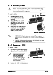
...force a DIMM into the socket until the retaining clips snap back in only one direction. Simultaneously press the retaining clips outward to both the motherboard and the components. Align a DIMM on the socket such that it flips out with your fingers when pressing the retaining clips. 2.4.3 Installing...The DDR2 DIMM sockets do so can cause severe damage to unlock the DIMM. Remove the DIMM from the socket. 2 1 DDR2 DIMM notch ASUS P5MT-M 2-15 Failure to do not support DDR DIMMs. DO not install DDR DIMMs to the DDR2 DIMM sockets. 2.4.4 Removing a DIMM To remove a DIMM:...
...force a DIMM into the socket until the retaining clips snap back in only one direction. Simultaneously press the retaining clips outward to both the motherboard and the components. Align a DIMM on the socket such that it flips out with your fingers when pressing the retaining clips. 2.4.3 Installing...The DDR2 DIMM sockets do so can cause severe damage to unlock the DIMM. Remove the DIMM from the socket. 2 1 DDR2 DIMM notch ASUS P5MT-M 2-15 Failure to do not support DDR DIMMs. DO not install DDR DIMMs to the DDR2 DIMM sockets. 2.4.4 Removing a DIMM To remove a DIMM:...


