
User Guide
Page 1
Motherboard P5MT Series P5MT P5MT/SCSI
Motherboard P5MT Series P5MT P5MT/SCSI

User Guide
Page 3
Contents Notices vi Safety information vii About this guide viii P5MT Series specifications summary x Chapter 1: Product introduction 1.1 Welcome 1-1 1.2 Package contents 1-1 1.3 Special features 1-2 1.3.1 Product highlights 1-2 1.3.2 Innovative ASUS features 1-4 Chapter 2: Hardware information 2.1 Before you proceed 2-1 2.2 Motherboard overview 2-2 2.2.1 Placement direction 2-2 2.2.2 Screw holes 2-2 2.2.3 Motherboard layouts 2-3 2.2.4 Layout contents 2-5 2.3 Central Processing Unit (CPU 2-7 2.3.1 Installing the CPU 2-7 2.3.2 Installing the CPU heatsink and...
Contents Notices vi Safety information vii About this guide viii P5MT Series specifications summary x Chapter 1: Product introduction 1.1 Welcome 1-1 1.2 Package contents 1-1 1.3 Special features 1-2 1.3.1 Product highlights 1-2 1.3.2 Innovative ASUS features 1-4 Chapter 2: Hardware information 2.1 Before you proceed 2-1 2.2 Motherboard overview 2-2 2.2.1 Placement direction 2-2 2.2.2 Screw holes 2-2 2.2.3 Motherboard layouts 2-3 2.2.4 Layout contents 2-5 2.3 Central Processing Unit (CPU 2-7 2.3.1 Installing the CPU 2-7 2.3.2 Installing the CPU heatsink and...
User Guide
Page 8
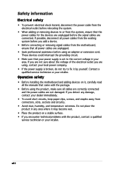
...a qualified service technician or your area. viii If you add a device. • Before connecting or removing signal cables from the motherboard, ensure that all power cables are unplugged. • Seek professional assistance before the signal cables are connected. If you are not ...electrical outlet before relocating the system. • When adding or removing devices to fix it by yourself. Operation safety • Before installing the motherboard and adding devices on a stable surface. • If you are not damaged. If possible, disconnect all power cables from the existing system ...
...a qualified service technician or your area. viii If you add a device. • Before connecting or removing signal cables from the motherboard, ensure that all power cables are unplugged. • Seek professional assistance before the signal cables are connected. If you are not ...electrical outlet before relocating the system. • When adding or removing devices to fix it by yourself. Operation safety • Before installing the motherboard and adding devices on a stable surface. • If you are not damaged. If possible, disconnect all power cables from the existing system ...
User Guide
Page 9
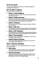
... description of the switches, jumpers, and connectors on ASUS hardware and software products. Refer to change system settings through the BIOS Setup menus. ASUS websites The ASUS website provides updated information on the motherboard. • Chapter 3: Powering up This chapter describes... the power up sequence and ways of the motherboard and the new technologies it supports. • ...
... description of the switches, jumpers, and connectors on ASUS hardware and software products. Refer to change system settings through the BIOS Setup menus. ASUS websites The ASUS website provides updated information on the motherboard. • Chapter 3: Powering up This chapter describes... the power up sequence and ways of the motherboard and the new technologies it supports. • ...

User Guide
Page 13
This chapter describes the motherboard features and the new technologies it supports. 1Product introduction
This chapter describes the motherboard features and the new technologies it supports. 1Product introduction
User Guide
Page 15
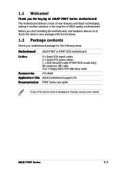
... another standout in -1 Floppy/Ultra ATA disk drive cable I/O shield ASUS motherboard support CD P5MT Series user guide If any of the above items is damaged or missing, contact your motherboard package for buying an ASUS® P5MT Series motherboard! Before you for the following items. Motherboard ASUS P5MT or P5MT/SCSI motherboard Cables Accessories Application CDs Documentation 4 x Serial ATA signal cables...
... another standout in -1 Floppy/Ultra ATA disk drive cable I/O shield ASUS motherboard support CD P5MT Series user guide If any of the above items is damaged or missing, contact your motherboard package for buying an ASUS® P5MT Series motherboard! Before you for the following items. Motherboard ASUS P5MT or P5MT/SCSI motherboard Cables Accessories Application CDs Documentation 4 x Serial ATA signal cables...

User Guide
Page 16
...meet the higher bandwidth requirements of system memory for the Intel® Pentium® 4 processor in packets. PCI Express™ interface The motherboard fully supports PCI Express, the latest I /O controller hub that speeds up to run on the CPU loading and system speed or power ...by carrying data in the 775-land package. See page 4-21 and the Appendix for PCI 2.3, USB 2.0, and SATA among others. The motherboard also supports the Intel® Hyper-Threading Technology and is a new generation server class I /O interconnect technology that provides the interface for details....
...meet the higher bandwidth requirements of system memory for the Intel® Pentium® 4 processor in packets. PCI Express™ interface The motherboard fully supports PCI Express, the latest I /O controller hub that speeds up to run on the CPU loading and system speed or power ...by carrying data in the 775-land package. See page 4-21 and the Appendix for PCI 2.3, USB 2.0, and SATA among others. The motherboard also supports the Intel® Hyper-Threading Technology and is a new generation server class I /O interconnect technology that provides the interface for details....

User Guide
Page 17
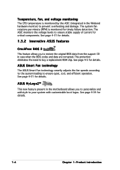
... to 15 SCSI devices. ASUS P5MT Series 1-3 See page 2-23 for details. Ultra320 SCSI feature (P5MT/SCSI model only) The LSI53C1020A PCI-X SCSI controller is backward compatible with USB 1.1. See page 2-27 and Chapter 5 for details. Serial ATA II technology The motherboard supports the Serial ATA II... technology through the Serial ATA interfaces controlled by the Intel® ICH7R. Built-in P5MT/SCSI model) that can connect up to create all types of RAID configurations...
... to 15 SCSI devices. ASUS P5MT Series 1-3 See page 2-23 for details. Ultra320 SCSI feature (P5MT/SCSI model only) The LSI53C1020A PCI-X SCSI controller is backward compatible with USB 1.1. See page 2-27 and Chapter 5 for details. Serial ATA II technology The motherboard supports the Serial ATA II... technology through the Serial ATA interfaces controlled by the Intel® ICH7R. Built-in P5MT/SCSI model) that can connect up to create all types of RAID configurations...
User Guide
Page 18
...page 4-34 for details. 1-4 Chapter 1: Product introduction The ASIC monitors the voltage levels to ensure quiet, cool, and efficient operation. ASUS MyLogo2™ This new feature present in case when the BIOS codes and data are corrupted. This protection eliminates the need to your system... the Winbond hardware monitor) to restore the original BIOS data from the support CD in the motherboard allows you to prevent overheating and damage. See page 4-31 for details. 1.3.2 Innovative ASUS features CrashFree BIOS 2 This feature allows you to personalize and add style to buy a replacement...
...page 4-34 for details. 1-4 Chapter 1: Product introduction The ASIC monitors the voltage levels to ensure quiet, cool, and efficient operation. ASUS MyLogo2™ This new feature present in case when the BIOS codes and data are corrupted. This protection eliminates the need to your system... the Winbond hardware monitor) to restore the original BIOS data from the support CD in the motherboard allows you to prevent overheating and damage. See page 4-31 for details. 1.3.2 Innovative ASUS features CrashFree BIOS 2 This feature allows you to personalize and add style to buy a replacement...

User Guide
Page 19
It includes description of the jumpers and connectors on the motherboard. 2 Hardware information This chapter lists the hardware setup procedures that you have to perform when installing system components.
It includes description of the jumpers and connectors on the motherboard. 2 Hardware information This chapter lists the hardware setup procedures that you have to perform when installing system components.
User Guide
Page 20
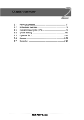
Chapter summary 2 2.1 Before you proceed 2-1 2.2 Motherboard overview 2-2 2.3 Central Processing Unit (CPU 2-7 2.4 System memory 2-13 2.5 Expansion slots 2-15 2.6 Jumpers 2-18 2.7 Connectors 2-23 ASUS P5MT Series
Chapter summary 2 2.1 Before you proceed 2-1 2.2 Motherboard overview 2-2 2.3 Central Processing Unit (CPU 2-7 2.4 System memory 2-13 2.5 Expansion slots 2-15 2.6 Jumpers 2-18 2.7 Connectors 2-23 ASUS P5MT Series
User Guide
Page 21
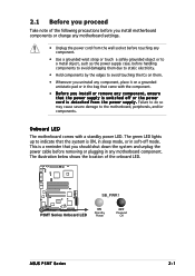
...w e r s u p p l y . This is a reminder that the system is switched off mode. The illustration below shows the location of the following precautions before you install motherboard components or change any motherboard settings. • Unplug the power cord from the wall socket before touching any component. • Use a grounded wrist strap or touch a safely grounded... damage to the motherboard, peripherals, and/or components. 2.1 Before you proceed Take note of the onboard LED. ® LAN2 SB_PWR1 P5MT Series Onboard LED ON Standby Power OFF Powered Off ASUS P5MT Series 2-1
...w e r s u p p l y . This is a reminder that the system is switched off mode. The illustration below shows the location of the following precautions before you install motherboard components or change any motherboard settings. • Unplug the power cord from the wall socket before touching any component. • Use a grounded wrist strap or touch a safely grounded... damage to the motherboard, peripherals, and/or components. 2.1 Before you proceed Take note of the onboard LED. ® LAN2 SB_PWR1 P5MT Series Onboard LED ON Standby Power OFF Powered Off ASUS P5MT Series 2-1

User Guide
Page 22
... into the chassis in the correct orientation. Failure to do so can damage the motherboard. Doing so can cause you physical injury and damage motherboard components! 2.2.1 Placement direction When installing the motherboard, make sure that you place it . 2.2 Motherboard overview Before you install the motherboard, study the configuration of your chassis to ensure that the...
... into the chassis in the correct orientation. Failure to do so can damage the motherboard. Doing so can cause you physical injury and damage motherboard components! 2.2.1 Placement direction When installing the motherboard, make sure that you place it . 2.2 Motherboard overview Before you install the motherboard, study the configuration of your chassis to ensure that the...

User Guide
Page 23
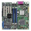
2.2.3 Motherboard layouts P5MT model PS/2KBMS KBPWR1 T: Mouse PSUSMB1 B: Keyboard USBPW12 USB12 REAR_FAN1 25cm (9.8in) ATXPWR1 ATX12V1 CPU_FAN1 COM1 REAR_FAN2 CPU_FAN2 FM_CPU2 Intel E7230 FM_CPU1 LGA775 PARALLEL PORT ® P5MT LAN_EN1 LAN_EN2 VGA1 LAN1 LAN2 Broadcom BCM5721 Broadcom BCM5721 DDR2 DIMM_A1 (64 bit,240-pin module) DDR2 DIMM_A2 (64 bit,240-pin module) DDR2... PCI4 BPSMB1 TRPWR1 AUX_PANEL1 BMCCONN1 HDLED1 CLRTC1 CR2032 3V Lithium Cell BUZZ1 CMOS Power USBPW34 USB34 PANEL1 Intel 6702 PXH FLOPPY1 PRI_IDE1 30.5cm (12in) ASUS P5MT Series 2-3
2.2.3 Motherboard layouts P5MT model PS/2KBMS KBPWR1 T: Mouse PSUSMB1 B: Keyboard USBPW12 USB12 REAR_FAN1 25cm (9.8in) ATXPWR1 ATX12V1 CPU_FAN1 COM1 REAR_FAN2 CPU_FAN2 FM_CPU2 Intel E7230 FM_CPU1 LGA775 PARALLEL PORT ® P5MT LAN_EN1 LAN_EN2 VGA1 LAN1 LAN2 Broadcom BCM5721 Broadcom BCM5721 DDR2 DIMM_A1 (64 bit,240-pin module) DDR2 DIMM_A2 (64 bit,240-pin module) DDR2... PCI4 BPSMB1 TRPWR1 AUX_PANEL1 BMCCONN1 HDLED1 CLRTC1 CR2032 3V Lithium Cell BUZZ1 CMOS Power USBPW34 USB34 PANEL1 Intel 6702 PXH FLOPPY1 PRI_IDE1 30.5cm (12in) ASUS P5MT Series 2-3

User Guide
Page 27
...Upon purchase of repair only if the damage is shipment/ transit-related. • Keep the cap after installing the motherboard. ASUS will shoulder the cost of the motherboard, make sure that the PnP cap is facing towards you see any damage to the socket contacts resulting from incorrect ...of the PnP cap. 2.3.1 Installing the CPU To install a CPU: 1. LAN2 P5MT Series CPU Socket 775 Before installing the CPU, make sure that the cam box is on the motherboard. Contact your left. ® ASUS P5MT Series 2-7 Locate the CPU socket on the socket and the socket contacts are not...
...Upon purchase of repair only if the damage is shipment/ transit-related. • Keep the cap after installing the motherboard. ASUS will shoulder the cost of the motherboard, make sure that the PnP cap is facing towards you see any damage to the socket contacts resulting from incorrect ...of the PnP cap. 2.3.1 Installing the CPU To install a CPU: 1. LAN2 P5MT Series CPU Socket 775 Before installing the CPU, make sure that the cam box is on the motherboard. Contact your left. ® ASUS P5MT Series 2-7 Locate the CPU socket on the socket and the socket contacts are not...
User Guide
Page 29
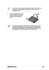
B The motherboard supports Intel® Pentium® 4 LGA775 processors with the Intel® Enhanced Memory 64 Technology (EM64T), Enhanced Intel SpeedStep® Technology (EIST), and Hyper-Threading Technology. DO NOT force the CPU into the retention tab. Refer to prevent bending the connectors on these CPU features. ASUS P5MT Series 2-9 The CPU fits in only one correct orientation. Close the load plate (A), then A push the load lever (B) until it snaps into the socket to the Appendix for more information on the socket and damaging the CPU! 6.
B The motherboard supports Intel® Pentium® 4 LGA775 processors with the Intel® Enhanced Memory 64 Technology (EM64T), Enhanced Intel SpeedStep® Technology (EIST), and Hyper-Threading Technology. DO NOT force the CPU into the retention tab. Refer to prevent bending the connectors on these CPU features. ASUS P5MT Series 2-9 The CPU fits in only one correct orientation. Close the load plate (A), then A push the load lever (B) until it snaps into the socket to the Appendix for more information on the socket and damaging the CPU! 6.

User Guide
Page 30
... Fastener Make sure to orient each fastener with the narrow end of the installed CPU, making sure that you have installed the motherboard to ensure optimum thermal condition and performance. • When you buy a CPU separately, make sure that you use only Intel®-certified multi-directional heatsink ... fan assembly. If you buy a boxed Intel® Pentium® 4 processor, the package includes the CPU fan and heatsink assembly. Place the heatsink on the motherboard.
... Fastener Make sure to orient each fastener with the narrow end of the installed CPU, making sure that you have installed the motherboard to ensure optimum thermal condition and performance. • When you buy a CPU separately, make sure that you use only Intel®-certified multi-directional heatsink ... fan assembly. If you buy a boxed Intel® Pentium® 4 processor, the package includes the CPU fan and heatsink assembly. Place the heatsink on the motherboard.
User Guide
Page 31
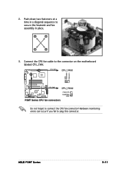
ASUS P5MT Series 2-11 A A A B B B A 3. Connect the CPU fan cable to connect the CPU fan connector! CPU_FAN1 CPU_FAN1 ® GND FANPWR2 FANOUT4 LAN2 CPU_FAN2 CPU_FAN2 FANOUT4 FANPWR2 GND P5MT Series CPU fan connectors Do not forget to the connector on the motherboard labeled CPU_FAN. Hardware monitoring errors can occur if you fail to secure the heatsink and fan B assembly in place. 2. Push down two fasteners at a time in a diagonal sequence to plug this connector.
ASUS P5MT Series 2-11 A A A B B B A 3. Connect the CPU fan cable to connect the CPU fan connector! CPU_FAN1 CPU_FAN1 ® GND FANPWR2 FANOUT4 LAN2 CPU_FAN2 CPU_FAN2 FANOUT4 FANPWR2 GND P5MT Series CPU fan connectors Do not forget to the connector on the motherboard labeled CPU_FAN. Hardware monitoring errors can occur if you fail to secure the heatsink and fan B assembly in place. 2. Push down two fasteners at a time in a diagonal sequence to plug this connector.

User Guide
Page 32
Disconnect the CPU fan cable from the A motherboard. Rotate each fastener counterclockwise. 3. Pull up two fasteners at a time in a diagonal sequence to disengage the heatsink and fan B assembly from the connector on the motherboard. 2. Carefully remove the heatsink and fan assembly from the motherboard. 2-12 Chapter 2: Hardware information A B A B B A 4. 2.3.3 Uninstalling the CPU heatsink and fan To uninstall the CPU heatsink and fan: 1.
Disconnect the CPU fan cable from the A motherboard. Rotate each fastener counterclockwise. 3. Pull up two fasteners at a time in a diagonal sequence to disengage the heatsink and fan B assembly from the connector on the motherboard. 2. Carefully remove the heatsink and fan assembly from the motherboard. 2-12 Chapter 2: Hardware information A B A B B A 4. 2.3.3 Uninstalling the CPU heatsink and fan To uninstall the CPU heatsink and fan: 1.
User Guide
Page 33
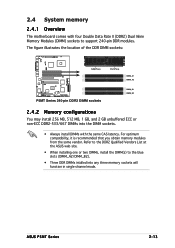
The figure illustrates the location of the DDR DIMM sockets: ® 128 Pins 112 Pins LAN2 DIMM_A1 DIMM_A2 P5MT Series 240-pin DDR2 DIMM sockets DIMM_B1 DIMM_B2 2.4.2 Memory configurations You may install 256 MB, 512 MB, 1 GB, and 2 GB unbuffered ECC or ...memory sockets will function in single-channel mode. ASUS P5MT Series 2-13 Refer to the DDR2 Qualified Vendors List at the ASUS web site. • When installing one or two DIMMs, install the DIMM(s) to support 240-pin DDR modules. 2.4 System memory 2.4.1 Overview The motherboard comes with the same CAS latency. For optimum...
The figure illustrates the location of the DDR DIMM sockets: ® 128 Pins 112 Pins LAN2 DIMM_A1 DIMM_A2 P5MT Series 240-pin DDR2 DIMM sockets DIMM_B1 DIMM_B2 2.4.2 Memory configurations You may install 256 MB, 512 MB, 1 GB, and 2 GB unbuffered ECC or ...memory sockets will function in single-channel mode. ASUS P5MT Series 2-13 Refer to the DDR2 Qualified Vendors List at the ASUS web site. • When installing one or two DIMMs, install the DIMM(s) to support 240-pin DDR modules. 2.4 System memory 2.4.1 Overview The motherboard comes with the same CAS latency. For optimum...


