
User Manual
Page 1
P5KPL-AM SE Motherboard
P5KPL-AM SE Motherboard
User Manual
Page 3
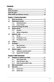
Contents Notices...v Safety information vi About this guide vi P5KPL-AM SE specifications summary viii Chapter 1: Product information 1.1 Before you proceed 1-1 1.2 Motherboard overview 1-2 1.2.1 Motherboard layout 1-2 1.2.2 Layout contents 1-2 1.3 Central Processing Unit (CPU 1-3 1.4 System memory 1-3 1.4.1 Overview 1-3 1.4.2 ... information 2.1 Managing and updating your BIOS 2-1 2.1.1 ASUS Update utility 2-1 2.1.2 ASUS EZ Flash 2 utility 2-2 2.1.3 ASUS CrashFree BIOS 3 utility 2-3 2.2 BIOS setup program 2-4 2.3 Main menu 2-4 2.3.1 System Time 2-4 2.3.2 System Date 2-4 iii
Contents Notices...v Safety information vi About this guide vi P5KPL-AM SE specifications summary viii Chapter 1: Product information 1.1 Before you proceed 1-1 1.2 Motherboard overview 1-2 1.2.1 Motherboard layout 1-2 1.2.2 Layout contents 1-2 1.3 Central Processing Unit (CPU 1-3 1.4 System memory 1-3 1.4.1 Overview 1-3 1.4.2 ... information 2.1 Managing and updating your BIOS 2-1 2.1.1 ASUS Update utility 2-1 2.1.2 ASUS EZ Flash 2 utility 2-2 2.1.3 ASUS CrashFree BIOS 3 utility 2-3 2.2 BIOS setup program 2-4 2.3 Main menu 2-4 2.3.1 System Time 2-4 2.3.2 System Date 2-4 iii
User Manual
Page 8
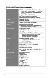
... on the next page) viii Maximum resolution: 2048 x 1536 x 32 bpp, - Maximum shared memory of 256 MB - P5KPL-AM SE specifications summary CPU Chipset Front Side Bus Memory Expansion Slots VGA Storage LAN Audio USB ASUS Features Rear panel LGA775 socket for Intel® Core™2 Quad/ Core™2 Extreme / Core™2 Duo...
... on the next page) viii Maximum resolution: 2048 x 1536 x 32 bpp, - Maximum shared memory of 256 MB - P5KPL-AM SE specifications summary CPU Chipset Front Side Bus Memory Expansion Slots VGA Storage LAN Audio USB ASUS Features Rear panel LGA775 socket for Intel® Core™2 Quad/ Core™2 Extreme / Core™2 Duo...
User Manual
Page 9
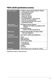
... P5KPL-AM SE specifications summary Internal connectors ASUS Exclusive Overclocking Features BIOS features Manageability Support DVD contents Accessories Form factor 2 x USB 2.0 connectors supports additional 4 USB ports 1 x internal speaker connector 2 x Serial ATA connectors 1 x CPU fan connector 1 x Chassis fan connector 1 x CD audio in (24.5 cm x 18.3cm) *Specifications are subject to 600MHz at 1MHz increment. ASUS...
... P5KPL-AM SE specifications summary Internal connectors ASUS Exclusive Overclocking Features BIOS features Manageability Support DVD contents Accessories Form factor 2 x USB 2.0 connectors supports additional 4 USB ports 1 x internal speaker connector 2 x Serial ATA connectors 1 x CPU fan connector 1 x Chassis fan connector 1 x CD audio in (24.5 cm x 18.3cm) *Specifications are subject to 600MHz at 1MHz increment. ASUS...
User Manual
Page 10
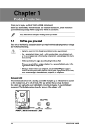
... you uninstall any motherboard component. This is...motherboard components or change any motherboard settings. • Unplug the power cord from the power supply. Refer to avoid touching the ICs on a grounded antistatic pad or in soft-off or the power cord is damaged or missing, contact your motherboard package. SB_PWR P5KPL-AM SE ON Standy Power P5KPL-AM SE Onboard LED OFF Powered Off 1-1 ASUS P5KPL...-AM SE...ASUS® P5KPL-AM SE motherboard! The illustration below ...
... you uninstall any motherboard component. This is...motherboard components or change any motherboard settings. • Unplug the power cord from the power supply. Refer to avoid touching the ICs on a grounded antistatic pad or in soft-off or the power cord is damaged or missing, contact your motherboard package. SB_PWR P5KPL-AM SE ON Standy Power P5KPL-AM SE Onboard LED OFF Powered Off 1-1 ASUS P5KPL...-AM SE...ASUS® P5KPL-AM SE motherboard! The illustration below ...
User Manual
Page 11
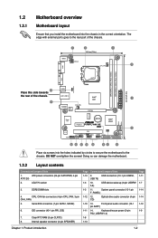
...EATXPWR LAN1_USB12 AUDIO RTL 8102EL CHA_FAN Intel® G31 PCIEX16 RTM870T-954 Super I/O Lithium Cell CMOS Power PCIEX1_1 P5KPL-AM SE SPEAKER Intel® ICH7 ALC662 AAFP F_PANEL CD PCI1 SB_PWR USBPW5-8 USB78 CLRTC USB56 PRI_IDE 8Mb BIOS SATA2 SATA1...1-14 1-12 1-9 Chapter 1: Product introduction 1-2 ATX power connectors (24-pin EATXPWR, 4-pin ATX12V) 2. DO NOT overtighten the screws! 1.2 1.2.1 Motherboard overview Motherboard layout Ensure that you install the motherboard into the holes indicated by circles to secure the motherboard to the rear part of the chassis. 24.4cm...
...EATXPWR LAN1_USB12 AUDIO RTL 8102EL CHA_FAN Intel® G31 PCIEX16 RTM870T-954 Super I/O Lithium Cell CMOS Power PCIEX1_1 P5KPL-AM SE SPEAKER Intel® ICH7 ALC662 AAFP F_PANEL CD PCI1 SB_PWR USBPW5-8 USB78 CLRTC USB56 PRI_IDE 8Mb BIOS SATA2 SATA1...1-14 1-12 1-9 Chapter 1: Product introduction 1-2 ATX power connectors (24-pin EATXPWR, 4-pin ATX12V) 2. DO NOT overtighten the screws! 1.2 1.2.1 Motherboard overview Motherboard layout Ensure that you install the motherboard into the holes indicated by circles to secure the motherboard to the rear part of the chassis. 24.4cm...
User Manual
Page 12
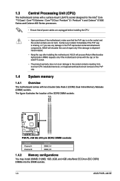
... installing the motherboard. ASUS will shoulder the cost of the DDR2 DIMM sockets: DIMM_A1 DIMM_B1 P5KPL-AM SE P5KPL-AM SE 240-pin DDR2 DIMM sockets Channel Channel A Channel B Sockets DIMM_A1 DIMM_B1 1.4.2 Memory configurations You may install 256MB, 512MB, 1GB, 2GB, and 4GB unbuffered ECC/non-ECC DDR2 DIMMs into the DIMM sockets. 1-3 ASUS P5KPL-AM SE The figure...
... installing the motherboard. ASUS will shoulder the cost of the DDR2 DIMM sockets: DIMM_A1 DIMM_B1 P5KPL-AM SE P5KPL-AM SE 240-pin DDR2 DIMM sockets Channel Channel A Channel B Sockets DIMM_A1 DIMM_B1 1.4.2 Memory configurations You may install 256MB, 512MB, 1GB, 2GB, and 4GB unbuffered ECC/non-ECC DDR2 DIMMs into the DIMM sockets. 1-3 ASUS P5KPL-AM SE The figure...
User Manual
Page 16
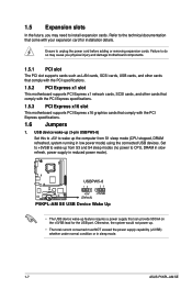
...5VSB to wake up from S1 sleep mode (CPU stopped, DRAM refreshed, system running in sleep mode. 1-7 ASUS P5KPL-AM SE 1.5 Expansion slots In the future, you physical injury and damage motherboard components. 1.5.1 PCI slot The PCI slot supports cards such as LAN cards, SCSI cards, USB cards, and...the PCI Express specifications. 1.5.3 PCI Express x16 slot This motherboard supports PCI Express x16 graphics cards that can provide 500mA on the +5VSB lead for installation details. USBPW5-8 12 23 P5KPL-AM SE +5V +5VSB (Default) P5KPL-AM SE USB Device Wake Up • The USB device wake-up...
...5VSB to wake up from S1 sleep mode (CPU stopped, DRAM refreshed, system running in sleep mode. 1-7 ASUS P5KPL-AM SE 1.5 Expansion slots In the future, you physical injury and damage motherboard components. 1.5.1 PCI slot The PCI slot supports cards such as LAN cards, SCSI cards, USB cards, and...the PCI Express specifications. 1.5.3 PCI Express x16 slot This motherboard supports PCI Express x16 graphics cards that can provide 500mA on the +5VSB lead for installation details. USBPW5-8 12 23 P5KPL-AM SE +5V +5VSB (Default) P5KPL-AM SE USB Device Wake Up • The USB device wake-up...

User Manual
Page 17
... RTC RAM: 1. Reinstall the battery. 5. Plug the power cord and turn off is required before rebooting the system. function. CLRTC 12 23 P5KPL-AM SE Normal (Default) Clear RTC P5KPL-AM SE Clear RTC RAM Chapter 1: Product introduction 1-8 Move the jumper cap from pins 1-2 (default) to clear the Real Time Clock (RTC) RAM in...
... RTC RAM: 1. Reinstall the battery. 5. Plug the power cord and turn off is required before rebooting the system. function. CLRTC 12 23 P5KPL-AM SE Normal (Default) Clear RTC P5KPL-AM SE Clear RTC RAM Chapter 1: Product introduction 1-8 Move the jumper cap from pins 1-2 (default) to clear the Real Time Clock (RTC) RAM in...
User Manual
Page 18
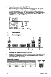
...default is the Space Bar), clicking the mouse, or using a USB device. This port is for the LAN port LED indications. This feature requires an ATX power supply that can wake up feature. Refer to a Local Area Network (LAN) through a network hub. LAN port LED indications Status OFF Blink ...No link Data activity Data activity Status OFF OFF Orange Speed LED Description No link 10M 100M ACT/LINK SPEED LED LED LAN port 1-9 ASUS P5KPL-AM SE Keyboard/mouse power (3-pin PS2_USBPW1-4) This jumper allows you set this port allows 10/100 connection to the table below for the rear ...
...default is the Space Bar), clicking the mouse, or using a USB device. This port is for the LAN port LED indications. This feature requires an ATX power supply that can wake up feature. Refer to a Local Area Network (LAN) through a network hub. LAN port LED indications Status OFF Blink ...No link Data activity Data activity Status OFF OFF Orange Speed LED Description No link 10M 100M ACT/LINK SPEED LED LED LAN port 1-9 ASUS P5KPL-AM SE Keyboard/mouse power (3-pin PS2_USBPW1-4) This jumper allows you set this port allows 10/100 connection to the table below for the rear ...

User Manual
Page 19
... 6. USB 2.0 ports 1 and 2. These two 4-pin Universal Serial Bus (USB) ports connect to a headphone or a speaker. P5KPL-AM SE SATA2 SATA1 GND RSATA_TXN2 RSATA_TXP2 GND RSATA_RXN2 RSATA_RXP2 GND GND RSATA_TXN2 RSATA_TXP1 GND RSATA_RXN1 RSATA_RXP1 GND P5KPL-AM SE SATA connectors (ICH7) right angle side Connect the right-angle side of this port becomes Front...
... 6. USB 2.0 ports 1 and 2. These two 4-pin Universal Serial Bus (USB) ports connect to a headphone or a speaker. P5KPL-AM SE SATA2 SATA1 GND RSATA_TXN2 RSATA_TXP2 GND RSATA_RXN2 RSATA_RXP2 GND GND RSATA_TXN2 RSATA_TXP1 GND RSATA_RXN1 RSATA_RXP1 GND P5KPL-AM SE SATA connectors (ICH7) right angle side Connect the right-angle side of this port becomes Front...
User Manual
Page 20
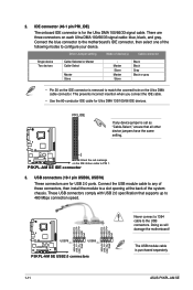
... blue connector to the motherboard's IDE connector, then...cable. P5KPL-AM SE IDE connector 3. These USB connectors comply with USB 2.0 specification that all other device jumpers have the same setting. Doing so will damage the motherboard! The... USB module cable is for Ultra DMA 133/100/66 IDE devices. PIN1 P5KPL-AM SE NOTE:Orient the red markings on each...USB connectors. PRI_IDE If any of the system chassis. USB+5V P5KPL-AM SE USB78 PIN 1 USB56 PIN 1 P5KPL-AM SE USB2.0 connectors USB+5V USB_P8- USB connectors (10-1 pin USB56,...
... blue connector to the motherboard's IDE connector, then...cable. P5KPL-AM SE IDE connector 3. These USB connectors comply with USB 2.0 specification that all other device jumpers have the same setting. Doing so will damage the motherboard! The... USB module cable is for Ultra DMA 133/100/66 IDE devices. PIN1 P5KPL-AM SE NOTE:Orient the red markings on each...USB connectors. PRI_IDE If any of the system chassis. USB+5V P5KPL-AM SE USB78 PIN 1 USB56 PIN 1 P5KPL-AM SE USB2.0 connectors USB+5V USB_P8- USB connectors (10-1 pin USB56,...
User Manual
Page 21
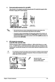
... PORT1 R PORT2 R SENSE_SEND PORT1 L P5KPL-AM SE HD-audio-compliant pin definition P5KPL-AM SE AAFP connector Legacy AC'97 compliant definition • We recommend that you connect a high-definition front panel audio module to this connector to avail of the motherboard's high-definition audio capability. •...Insufficient air flow inside the system may damage the motherboard components. P5KPL-AM SE CPU_FAN CPU FAN PWM CPU FAN IN CPU FAN PWR GND CHA_FAN Rotation +12V GND P5KPL-AM SE fan connectors Only the CPU_FAN connector support the ASUS Advanced Q-Fan feature. if you want to ...
... PORT1 R PORT2 R SENSE_SEND PORT1 L P5KPL-AM SE HD-audio-compliant pin definition P5KPL-AM SE AAFP connector Legacy AC'97 compliant definition • We recommend that you connect a high-definition front panel audio module to this connector to avail of the motherboard's high-definition audio capability. •...Insufficient air flow inside the system may damage the motherboard components. P5KPL-AM SE CPU_FAN CPU FAN PWM CPU FAN IN CPU FAN PWR GND CHA_FAN Rotation +12V GND P5KPL-AM SE fan connectors Only the CPU_FAN connector support the ASUS Advanced Q-Fan feature. if you want to ...
User Manual
Page 22
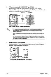
... connectors in only one orientation. The system may become unstable or may not boot up if the power is for ATX power supply plugs. ATX12V EATXPWR +12V DC +12V DC P5KPL-AM SE GND GND +3 Volts +12 Volts +12 Volts +5V Standby Power OK GND PIN 1 +5 Volts GND +5 Volts GND +3...of 400 W. • Do not forget to connect the 4-pin ATX12V power plug. SPEAKER +5V GND GND Speaker Out P5KPL-AM SE PIN 1 P5KPL-AM SE Speaker Out Connector 1-13 ASUS P5KPL-AM SE Find the proper orientation and push down firmly until the connectors completely fit. 6. The power supply plugs are for the ...
... connectors in only one orientation. The system may become unstable or may not boot up if the power is for ATX power supply plugs. ATX12V EATXPWR +12V DC +12V DC P5KPL-AM SE GND GND +3 Volts +12 Volts +12 Volts +5V Standby Power OK GND PIN 1 +5 Volts GND +5 Volts GND +3...of 400 W. • Do not forget to connect the 4-pin ATX12V power plug. SPEAKER +5V GND GND Speaker Out P5KPL-AM SE PIN 1 P5KPL-AM SE Speaker Out Connector 1-13 ASUS P5KPL-AM SE Find the proper orientation and push down firmly until the connectors completely fit. 6. The power supply plugs are for the ...
User Manual
Page 23
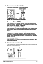
Connect the HDD Activity LED cable to this connector. CD Right Audio Channel GND GND Left Audio Channel P5KPL-AM SE P5KPL-AM SE Internal audio connector Chapter 1: Product introduction 1-14 Pressing the power button turns the system on or puts the system in sleep or ...Ground Reset 8. The IDE LED lights up when you to the HDD. • ATX power button/soft-off the system power. 9. PLED+ PLEDPWR GND IDE_LED+ IDE_LED- PWR LED PWR BTN F_PANEL PIN 1 P5KPL-AM SE HD_LED RESET P5KPL-AM SE System panel connector • System power LED (2-pin PWRLED) This 2-pin connector is ...
Connect the HDD Activity LED cable to this connector. CD Right Audio Channel GND GND Left Audio Channel P5KPL-AM SE P5KPL-AM SE Internal audio connector Chapter 1: Product introduction 1-14 Pressing the power button turns the system on or puts the system in sleep or ...Ground Reset 8. The IDE LED lights up when you to the HDD. • ATX power button/soft-off the system power. 9. PLED+ PLEDPWR GND IDE_LED+ IDE_LED- PWR LED PWR BTN F_PANEL PIN 1 P5KPL-AM SE HD_LED RESET P5KPL-AM SE System panel connector • System power LED (2-pin PWRLED) This 2-pin connector is ...
User Manual
Page 24
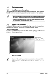
... Pack 1 or later versions before installing the drivers for reference only. Double-click the ASSETUP.EXE to avail all motherboard features. To run the DVD. 1-15 ASUS P5KPL-AM SE 1.8 Software support 1.8.1 Installing an operating system This motherboard supports Windows® XP/Vista Operating Systems (OS). Use the setup procedures presented in your hardware. •...
... Pack 1 or later versions before installing the drivers for reference only. Double-click the ASSETUP.EXE to avail all motherboard features. To run the DVD. 1-15 ASUS P5KPL-AM SE 1.8 Software support 1.8.1 Installing an operating system This motherboard supports Windows® XP/Vista Operating Systems (OS). Use the setup procedures presented in your hardware. •...
User Manual
Page 26
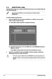
...BIOS file is found. 2. Press to display the following: ASUSTek EZ Flash 2 BIOS ROM Utility V3.25 FLASH TYPE: MXIC 25L8005 Current ROM BOARD: P5KPL-AM SE VER: 0309 (H:00 B:01) DATE: 09/28/2008 Update ROM BOARD: Unknown VER: Unknown DATE: Unknown PATH: A:\ A: Note [Enter] Select or...EZ Flash 2 and press to prevent system boot failure! 2-2 ASUS P5KPL-AM SE 2.1.2 ASUS EZ Flash 2 utility ASUS EZ Flash 2 allows you to update the BIOS without having to use a bootable floppy disk and a DOS‑based utility. Download the latest BIOS file for this motherboard from the ASUS website at www...
...BIOS file is found. 2. Press to display the following: ASUSTek EZ Flash 2 BIOS ROM Utility V3.25 FLASH TYPE: MXIC 25L8005 Current ROM BOARD: P5KPL-AM SE VER: 0309 (H:00 B:01) DATE: 09/28/2008 Update ROM BOARD: Unknown VER: Unknown DATE: Unknown PATH: A:\ A: Note [Enter] Select or...EZ Flash 2 and press to prevent system boot failure! 2-2 ASUS P5KPL-AM SE 2.1.2 ASUS EZ Flash 2 utility ASUS EZ Flash 2 allows you to update the BIOS without having to use a bootable floppy disk and a DOS‑based utility. Download the latest BIOS file for this motherboard from the ASUS website at www...
User Manual
Page 28
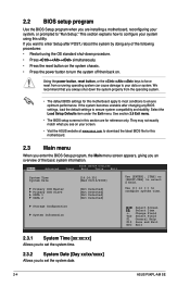
...See section 2.8 Exit menu. • The BIOS setup screens in this section are installing a motherboard, reconfiguring your screen. • Visit the ASUS website at www.asus.com to download the latest BIOS file for this motherboard. 2.3 Main menu When you enter the BIOS Setup program, the Main menu screen appears, ... you to turn the system off then back on the system chassis. • Press the power button to set the system date. 2-4 ASUS P5KPL-AM SE Using the power button, reset button, or the ++ keys to your system using the OS standard shut-down the system properly from a ...
...See section 2.8 Exit menu. • The BIOS setup screens in this section are installing a motherboard, reconfiguring your screen. • Visit the ASUS website at www.asus.com to download the latest BIOS file for this motherboard. 2.3 Main menu When you enter the BIOS Setup program, the Main menu screen appears, ... you to turn the system off then back on the system chassis. • Press the power button to set the system date. 2-4 ASUS P5KPL-AM SE Using the power button, reset button, or the ++ keys to your system using the OS standard shut-down the system properly from a ...
User Manual
Page 30
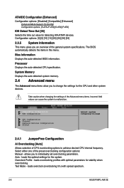
... changing the settings of the preset overclocking configuration options: Manual - Auto - loads the optimal settings for stability when overclocking. loads overclocking profiles with spread spectrum. 2-6 ASUS P5KPL-AM SE
... changing the settings of the preset overclocking configuration options: Manual - Auto - loads the optimal settings for stability when overclocking. loads overclocking profiles with spread spectrum. 2-6 ASUS P5KPL-AM SE
User Manual
Page 32
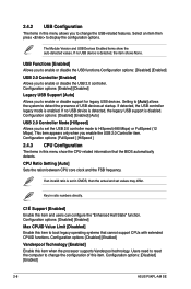
.... Configuration options: [Enabled] [Disabled] Legacy USB Support [Auto] Allows you to boot legacy operating systems that the BIOS automatically detects. Configuration options: [Disabled] [Enabled] 2-8 ASUS P5KPL-AM SE If an invalid ratio is enabled. The Module Version and USB Devices Enabled items show the CPU-related information that cannot support CPUs with extended...
.... Configuration options: [Enabled] [Disabled] Legacy USB Support [Auto] Allows you to boot legacy operating systems that the BIOS automatically detects. Configuration options: [Disabled] [Enabled] 2-8 ASUS P5KPL-AM SE If an invalid ratio is enabled. The Module Version and USB Devices Enabled items show the CPU-related information that cannot support CPUs with extended...


