User Manual
Page 13
... you for the following items. Motherboard I/O module Cables Accessory Application CD Documentation ASUS P5GDC Pro motherboard 1 x Serial port module 2 x Serial ATA signal cables 1 x Ultra DMA 133/100/66 cable 1 x FDD cable I/O shield ASUS motherboard support CD User guide If any of ASUS quality motherboards! ASUS P5GDC Pro 1-1 The motherboard delivers a host of new features and latest technologies, making...
... you for the following items. Motherboard I/O module Cables Accessory Application CD Documentation ASUS P5GDC Pro motherboard 1 x Serial port module 2 x Serial ATA signal cables 1 x Ultra DMA 133/100/66 cable 1 x FDD cable I/O shield ASUS motherboard support CD User guide If any of ASUS quality motherboards! ASUS P5GDC Pro 1-1 The motherboard delivers a host of new features and latest technologies, making...
User Manual
Page 15
... for various audio devices. Gigabit LAN The motherboard comes with a Gigabit LAN controller to determine audio device classes, and pre-defined equalization for 7.1-channel feedback. ASUS P5GDC Pro 1-3 See page 2-23 for four Serial ATA connectors and supports the Intel® Matrix Storage Technology. See page 5-15 for details. This digital stream passes...
... for various audio devices. Gigabit LAN The motherboard comes with a Gigabit LAN controller to determine audio device classes, and pre-defined equalization for 7.1-channel feedback. ASUS P5GDC Pro 1-3 See page 2-23 for four Serial ATA connectors and supports the Intel® Matrix Storage Technology. See page 5-15 for details. This digital stream passes...
User Manual
Page 17
...This feature allows you to personalize and add style to ensure quiet, cool, and efficient operation. See page 4-26 for details. ASUS Q-Fan technology The ASUS Q-Fan technology smartly adjusts the CPU fan speed according to the system loading to your system with Intel® PAT improves memory ... between the CPU and the system memory. This protection eliminates the need to restore the original BIOS data from a floppy disk. ASUS P5GDC Pro 1-5 ASUS CrashFree BIOS 2 This feature allows you can easily update the system BIOS even before loading the operating system.
...This feature allows you to personalize and add style to ensure quiet, cool, and efficient operation. See page 4-26 for details. ASUS Q-Fan technology The ASUS Q-Fan technology smartly adjusts the CPU fan speed according to the system loading to your system with Intel® PAT improves memory ... between the CPU and the system memory. This protection eliminates the need to restore the original BIOS data from a floppy disk. ASUS P5GDC Pro 1-5 ASUS CrashFree BIOS 2 This feature allows you can easily update the system BIOS even before loading the operating system.

User Manual
Page 20
Chapter summary 2 2.1 Before you proceed 2-1 2.2 Motherboard overview 2-2 2.3 Central Processing Unit (CPU 2-6 2.4 System memory 2-13 2.5 Expansion slots 2-21 2.6 Jumpers 2-24 2.7 Connectors 2-27 ASUS P5GDC Pro
Chapter summary 2 2.1 Before you proceed 2-1 2.2 Motherboard overview 2-2 2.3 Central Processing Unit (CPU 2-6 2.4 System memory 2-13 2.5 Expansion slots 2-21 2.6 Jumpers 2-24 2.7 Connectors 2-27 ASUS P5GDC Pro

User Manual
Page 21
... proceed Take note of the onboard LED. The illustration below shows the location of the following precautions before you install or remove any motherboard component. P5GDC PRO SB_PWR1 ON Standby P5GDC PRO Onboard LED Power OFF Powered Off ASUS P5GDC Pro 2-1
... proceed Take note of the onboard LED. The illustration below shows the location of the following precautions before you install or remove any motherboard component. P5GDC PRO SB_PWR1 ON Standby P5GDC PRO Onboard LED Power OFF Powered Off ASUS P5GDC Pro 2-1

User Manual
Page 23
...:Line Out Below:Mic In PWR_FAN1 Intel R MCH 915P PRI_IDE1 Marvell 88E8053 CHA_FAN2 P5GDC PRO PCIEX16 PCI1 PCI2 PCI3 AAFP PCIEX1_1 CMI9880 SB_PWR1 PCIEX1_2 CD COM1 R Intel ICH6R SATA3 SATA4 CR2032 3V Lithium Cell CMOS Power CLRTC1 USB56 USB78 USBPW56 USBPW78 Intel FWH 4Mb Super I/O SATA1 SATA2 FLOPPY1 GAME1 CHASSIS1 CHA_FAN1 PANEL1 ASUS P5GDC Pro 2-3
...:Line Out Below:Mic In PWR_FAN1 Intel R MCH 915P PRI_IDE1 Marvell 88E8053 CHA_FAN2 P5GDC PRO PCIEX16 PCI1 PCI2 PCI3 AAFP PCIEX1_1 CMI9880 SB_PWR1 PCIEX1_2 CD COM1 R Intel ICH6R SATA3 SATA4 CR2032 3V Lithium Cell CMOS Power CLRTC1 USB56 USB78 USBPW56 USBPW78 Intel FWH 4Mb Super I/O SATA1 SATA2 FLOPPY1 GAME1 CHASSIS1 CHA_FAN1 PANEL1 ASUS P5GDC Pro 2-3

User Manual
Page 25
... (16-1 pin GAME) 13. Reset switch (Blue 2-pin RESET) Page 2-29 2-30 2-31 2-32 2-32 2-32 2-33 2-33 2-34 2-34 2-35 2-35 2-36 2-37 2-38 ASUS P5GDC Pro 2-5 Chassis intrusion connector (4-1 pin CHASSIS1) 14. Serial ATA connectors (7-pin SATA1, SATA2, SATA3, SATA4) 4. System Power LED (Green 3-pin PLED) -
... (16-1 pin GAME) 13. Reset switch (Blue 2-pin RESET) Page 2-29 2-30 2-31 2-32 2-32 2-32 2-33 2-33 2-34 2-34 2-35 2-35 2-36 2-37 2-38 ASUS P5GDC Pro 2-5 Chassis intrusion connector (4-1 pin CHASSIS1) 14. Serial ATA connectors (7-pin SATA1, SATA2, SATA3, SATA4) 4. System Power LED (Green 3-pin PLED) -
User Manual
Page 27
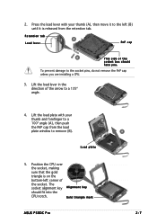
... of the socket. To prevent damage to a 135º angle. 4. Load plate 5. The socket alignment key A l i g n m e n t k e y should face you are installing a CPU. 3. Gold triangle mark ASUS P5GDC Pro A 2-7 Lift the load lever in the direction of the socket box should fit into the CPU notch. Retention tab A Load lever PnP cap B This side...
... of the socket. To prevent damage to a 135º angle. 4. Load plate 5. The socket alignment key A l i g n m e n t k e y should face you are installing a CPU. 3. Gold triangle mark ASUS P5GDC Pro A 2-7 Lift the load lever in the direction of the socket box should fit into the CPU notch. Retention tab A Load lever PnP cap B This side...

User Manual
Page 29
... fan assembly such that the four fasteners match the holes on top of the groove pointing outward. (The photo shows the groove shaded for emphasis.) ASUS P5GDC Pro 2-9 Make sure that you have properly applied Thermal Interface Material to the CPU heatsink or CPU before you install the CPU fan and heatsink assembly...
... fan assembly such that the four fasteners match the holes on top of the groove pointing outward. (The photo shows the groove shaded for emphasis.) ASUS P5GDC Pro 2-9 Make sure that you have properly applied Thermal Interface Material to the CPU heatsink or CPU before you install the CPU fan and heatsink assembly...

User Manual
Page 31
Disconnect the CPU fan cable from the A motherboard. Pull up two fasteners at a time in a diagonal sequence to disengage the heatsink B and fan assembly from the connector on the motherboard. 2. A B A B B A ASUS P5GDC Pro 2-11 Rotate each fastener counterclockwise. 3. 2.3.3 Uninstalling the CPU heatsink and fan To uninstall the CPU heatsink and fan: 1.
Disconnect the CPU fan cable from the A motherboard. Pull up two fasteners at a time in a diagonal sequence to disengage the heatsink B and fan assembly from the connector on the motherboard. 2. A B A B B A ASUS P5GDC Pro 2-11 Rotate each fastener counterclockwise. 3. 2.3.3 Uninstalling the CPU heatsink and fan To uninstall the CPU heatsink and fan: 1.
User Manual
Page 33
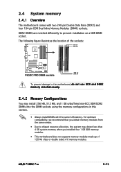
2.4 System memory 2.4.1 Overview The motherboard comes with the same CAS latency. ASUS P5GDC Pro 2-13 The following figure illustrates the location of 128 Mb chips or double sided x16 memory modules. DDR2 DIMMS are notched differently to the motherboard, d o n o t u s e D D R a n d D D R 2 ... system memory when you installed four 1 GB DDR memory modules. • This motherboard does not support memory modules made up of the sockets: DDR_B1 DDR_B2 P5GDC PRO DDR2_A1 DDR2_B1 P5GDC PRO DIMM sockets DDR_A2 DDR_A1 To prevent damage to prevent installation on a DDR DIMM socket.
2.4 System memory 2.4.1 Overview The motherboard comes with the same CAS latency. ASUS P5GDC Pro 2-13 The following figure illustrates the location of 128 Mb chips or double sided x16 memory modules. DDR2 DIMMS are notched differently to the motherboard, d o n o t u s e D D R a n d D D R 2 ... system memory when you installed four 1 GB DDR memory modules. • This motherboard does not support memory modules made up of the sockets: DDR_B1 DDR_B2 P5GDC PRO DDR2_A1 DDR2_B1 P5GDC PRO DIMM sockets DDR_A2 DDR_A1 To prevent damage to prevent installation on a DDR DIMM socket.

User Manual
Page 37
S S - supports one pair of modules inserted into both yellow slots as one module inserted in any yellow slot in a Single-channel memory configuration. Double-sided ASUS P5GDC Pro 2-17 supports one pair of Dual-channel memory configuration. Single-sided D S - DDR2 (533MHz) Qualified Vendors List Size Vendor Model Brand Side/s* Component DIMM support (optional) ...
S S - supports one pair of modules inserted into both yellow slots as one module inserted in any yellow slot in a Single-channel memory configuration. Double-sided ASUS P5GDC Pro 2-17 supports one pair of Dual-channel memory configuration. Single-sided D S - DDR2 (533MHz) Qualified Vendors List Size Vendor Model Brand Side/s* Component DIMM support (optional) ...

User Manual
Page 39
... a DIMM socket by pressing the retaining clips outward. 2. DO NOT force a DIMM into the socket until the retaining clips snap back in only one direction. ASUS P5GDC Pro 2-19 2.4.3 Installing a DDR DIMM Make sure to both the motherboard and the components. 1. Failure to do so may cause severe damage to unplug the power...
... a DIMM socket by pressing the retaining clips outward. 2. DO NOT force a DIMM into the socket until the retaining clips snap back in only one direction. ASUS P5GDC Pro 2-19 2.4.3 Installing a DDR DIMM Make sure to both the motherboard and the components. 1. Failure to do so may cause severe damage to unplug the power...
User Manual
Page 41
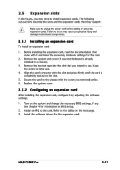
Align the card connector with it by adjusting the software settings. 1. ASUS P5GDC Pro 2-21 Failure to do so may need to the tables on BIOS setup. 2. Before installing the expansion card, read the documentation that came with the ...
Align the card connector with it by adjusting the software settings. 1. ASUS P5GDC Pro 2-21 Failure to do so may need to the tables on BIOS setup. 2. Before installing the expansion card, read the documentation that came with the ...
User Manual
Page 43
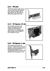
The figure shows a LAN card installed on the PCI Express x1 slot. ASUS P5GDC Pro 2-23 The following figure shows a graphics card installed on the PCI Express x16 slot. 2.5.6 PCI Express x1 slot This motherboard supports PCI Express x1 network ...
The figure shows a LAN card installed on the PCI Express x1 slot. ASUS P5GDC Pro 2-23 The following figure shows a graphics card installed on the PCI Express x16 slot. 2.5.6 PCI Express x1 slot This motherboard supports PCI Express x1 network ...

User Manual
Page 45
... power up feature requires a power supply that you can provide 500mA on the +5VSB lead for each USB port; P5GDC PRO USBPW12 USBPW34 2 1 +5V (Default) 3 2 +5VSB USBPW56 USBPW78 12 23 +5V P5GDC PRO USB device wake-up (Default) +5VSB • The USB device wake-up . • The total current consumed...internal USB connectors that can connect to wake up from S1 sleep mode (CPU stopped, DRAM refreshed, system running in sleep mode. ASUS P5GDC Pro 2-25 2 . USB device wake-up (3-pin USBPW12, USBPW34, USBPW56, USBPW78) Set these jumpers to +5V to additional USB ports.
... power up feature requires a power supply that you can provide 500mA on the +5VSB lead for each USB port; P5GDC PRO USBPW12 USBPW34 2 1 +5V (Default) 3 2 +5VSB USBPW56 USBPW78 12 23 +5V P5GDC PRO USB device wake-up (Default) +5VSB • The USB device wake-up . • The total current consumed...internal USB connectors that can connect to wake up from S1 sleep mode (CPU stopped, DRAM refreshed, system running in sleep mode. ASUS P5GDC Pro 2-25 2 . USB device wake-up (3-pin USBPW12, USBPW34, USBPW56, USBPW78) Set these jumpers to +5V to additional USB ports.
User Manual
Page 47
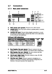
.../LINK SPEED LED LED LAN port 4 . This port connects a headphone or a speaker. This port connects the rear speakers on a 4-channel, 6-channel, or 8-channel audio configuration. 5 . ASUS P5GDC Pro 2-27 P a r a l l e l p o r t . Refer to a Local Area Network (LAN) through a network hub. R e a r S p e a k e r O u t p o r t ( g r a y ) . 2.7 Connectors 2.7.1 Rear panel connectors 1 2 34 5 6 7 8 13 12 11 10 9 1 . P S / 2 m o u s e p o r t ( g r e e n ) . This port is for the LAN...
.../LINK SPEED LED LED LAN port 4 . This port connects a headphone or a speaker. This port connects the rear speakers on a 4-channel, 6-channel, or 8-channel audio configuration. 5 . ASUS P5GDC Pro 2-27 P a r a l l e l p o r t . Refer to a Local Area Network (LAN) through a network hub. R e a r S p e a k e r O u t p o r t ( g r a y ) . 2.7 Connectors 2.7.1 Rear panel connectors 1 2 34 5 6 7 8 13 12 11 10 9 1 . P S / 2 m o u s e p o r t ( g r e e n ) . This port is for the LAN...

User Manual
Page 49
Floppy disk drive connector (34-1 pin FLOPPY1) This connector is removed to prevent incorrect cable connection when using an FDD cable with a covered Pin 5. P5GDC PRO Floppy disk drive connector ASUS P5GDC Pro 2-29 Insert one end of the floppy disk drive. P5GDC PRO FLOPPY1 PIN 1 NOTE: Orient the red markings on the connector is for the provided floppy disk drive (FDD) signal cable. Pin 5 on the floppy ribbon cable to the signal connector at the back of the cable to this connector, then connect the other end to PIN 1. 2.7.2 Internal connectors 1 .
Floppy disk drive connector (34-1 pin FLOPPY1) This connector is removed to prevent incorrect cable connection when using an FDD cable with a covered Pin 5. P5GDC PRO Floppy disk drive connector ASUS P5GDC Pro 2-29 Insert one end of the floppy disk drive. P5GDC PRO FLOPPY1 PIN 1 NOTE: Orient the red markings on the connector is for the provided floppy disk drive (FDD) signal cable. Pin 5 on the floppy ribbon cable to the signal connector at the back of the cable to this connector, then connect the other end to PIN 1. 2.7.2 Internal connectors 1 .
User Manual
Page 51
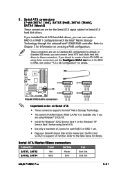
... RSATA_RXN4 GND GND RSATA_TXP3 RSATA_TXN3 GND RSATA_RXP3 RSATA_RXN3 GND SATA1 SATA2 GND RSATA_TXP2 RSATA_TXN2 GND RSATA_RXP2 RSATA_RXN2 GND GND RSATA_TXP1 RSATA_TXN1 GND RSATA_RXP1 RSATA_RXN1 GND P5GDC PRO SATA connectors Important notes on the master port (SATA1 and SATA2) to create a Serial ATA RAID set the C o n f i g... ATA Master/Slave connectors Connector Color Setting SATA1, SATA2 Red Master SATA3, SATA4 Black Slave Use Boot Disk Data Disk ASUS P5GDC Pro 2-31 Refer to RAID. Serial ATA connectors (7-pin SATA1 [red], SATA2 [red], SATA3 [black], SATA4 [black])...
... RSATA_RXN4 GND GND RSATA_TXP3 RSATA_TXN3 GND RSATA_RXP3 RSATA_RXN3 GND SATA1 SATA2 GND RSATA_TXP2 RSATA_TXN2 GND RSATA_RXP2 RSATA_RXN2 GND GND RSATA_TXP1 RSATA_TXN1 GND RSATA_RXP1 RSATA_RXN1 GND P5GDC PRO SATA connectors Important notes on the master port (SATA1 and SATA2) to create a Serial ATA RAID set the C o n f i g... ATA Master/Slave connectors Connector Color Setting SATA1, SATA2 Red Master SATA3, SATA4 Black Slave Use Boot Disk Data Disk ASUS P5GDC Pro 2-31 Refer to RAID. Serial ATA connectors (7-pin SATA1 [red], SATA2 [red], SATA3 [black], SATA4 [black])...

User Manual
Page 53
...any of these connectors, then install the module to a slot opening at the back of the system chassis. USB+5V USB_P8USB_P8+ GND NC P5GDC PRO USB56 1 P5GDC PRO USB 2.0 connectors USB+5V USB_P6USB_P6+ GND NC USB78 1 USB+5V USB_P7USB_P7+ GND USB+5V USB_P5USB_P5+ GND Never connect a 1 3 ... is purchased separately. These USB connectors comply with USB 2.0 specification that supports up to the USB connectors. P5GDC PRO COM1 PIN 1 P5GDC PRO Serial port connector 6 . ASUS P5GDC Pro 2-33 The USB/GAME module is for USB 2.0 ports. USB connectors (10-1 pin USB56, USB78) These...
...any of these connectors, then install the module to a slot opening at the back of the system chassis. USB+5V USB_P8USB_P8+ GND NC P5GDC PRO USB56 1 P5GDC PRO USB 2.0 connectors USB+5V USB_P6USB_P6+ GND NC USB78 1 USB+5V USB_P7USB_P7+ GND USB+5V USB_P5USB_P5+ GND Never connect a 1 3 ... is purchased separately. These USB connectors comply with USB 2.0 specification that supports up to the USB connectors. P5GDC PRO COM1 PIN 1 P5GDC PRO Serial port connector 6 . ASUS P5GDC Pro 2-33 The USB/GAME module is for USB 2.0 ports. USB connectors (10-1 pin USB56, USB78) These...


