
P5GD1 User's Manual English Version E1745
Page 12
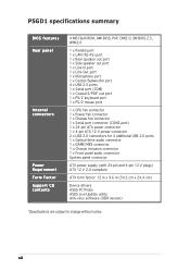
P5GD1 specifications summary BIOS features Rear panel Internal connectors Power Requirement Form Factor Support CD contents 4 MB Flash ROM, AMI BIOS, PnP, DMI2.0, SM BIOS 2.3, WfM2.0 1 x Parallel port 1 x LAN (RJ-45) port 1 x Rear speaker out port 1 x Side speaker out port 1 x Line In ... ATX power supply (with 24-pin and 4-pin 12 V plugs) ATX 12 V 2.0 compliant ATX form factor: 12 in x 9.6 in (30.5 cm x 24.4 cm) Device drivers ASUS PC Probe ASUS Live Update utility Anti-virus software (OEM version) *Specifications are subject to change without notice. xii
P5GD1 specifications summary BIOS features Rear panel Internal connectors Power Requirement Form Factor Support CD contents 4 MB Flash ROM, AMI BIOS, PnP, DMI2.0, SM BIOS 2.3, WfM2.0 1 x Parallel port 1 x LAN (RJ-45) port 1 x Rear speaker out port 1 x Side speaker out port 1 x Line In ... ATX power supply (with 24-pin and 4-pin 12 V plugs) ATX 12 V 2.0 compliant ATX form factor: 12 in x 9.6 in (30.5 cm x 24.4 cm) Device drivers ASUS PC Probe ASUS Live Update utility Anti-virus software (OEM version) *Specifications are subject to change without notice. xii

P5GD1 User's Manual English Version E1745
Page 16
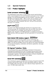
... Pentium® 4 processor in packets. This high speed interface is software compatible with 800 MHz Front Side Bus (FSB), 1 MB L2 cache, and core speed of system memory using DDR400/333 DIMMs. The ultra-fast 400MHz memory bus delivers the required bandwidth for...1.3 Special features 1.3.1 Product highlights Latest processor technology The motherboard comes with lower pin count, reduced voltage requirement, and up to 150 MB/s data transfer rate. 1-2 Chapter 1: Product introduction Serial ATA technology The motherboard supports the Serial ATA technology through the Serial ATA interfaces...
... Pentium® 4 processor in packets. This high speed interface is software compatible with 800 MHz Front Side Bus (FSB), 1 MB L2 cache, and core speed of system memory using DDR400/333 DIMMs. The ultra-fast 400MHz memory bus delivers the required bandwidth for...1.3 Special features 1.3.1 Product highlights Latest processor technology The motherboard comes with lower pin count, reduced voltage requirement, and up to 150 MB/s data transfer rate. 1-2 Chapter 1: Product introduction Serial ATA technology The motherboard supports the Serial ATA technology through the Serial ATA interfaces...

P5GD1 User's Manual English Version E1745
Page 31
... allocation, the system may detect less than the recommended configurations may install 256 MB, 512 MB and 1 GB unbuffered non-ECC DDR DIMMs into the DIMM sockets using the... memory configurations in this motherboard. Use any of the sockets: DIMM_A1 DIMM_A2 DIMM_B1 DIMM_B2 P5GD1 P5GD1...memory whne you installed four 1 GB DDR memory modules. • Due to chipset limitation, DIMM modules with 128 Mb memory chips or double-sided x16 memory chips are not supported in Table 1. • In dual-channel configurations,...
... allocation, the system may detect less than the recommended configurations may install 256 MB, 512 MB and 1 GB unbuffered non-ECC DDR DIMMs into the DIMM sockets using the... memory configurations in this motherboard. Use any of the sockets: DIMM_A1 DIMM_A2 DIMM_B1 DIMM_B2 P5GD1 P5GD1...memory whne you installed four 1 GB DDR memory modules. • Due to chipset limitation, DIMM modules with 128 Mb memory chips or double-sided x16 memory chips are not supported in Table 1. • In dual-channel configurations,...

P5GD1 User's Manual English Version E1745
Page 48
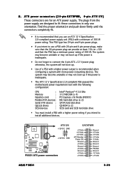
...type has 24-pin and 4-pin power plugs. • If you use a PSU with more power-consuming devices. ATX12V +12V DC GND +12V DC GND P5GD1 P5GD1 ATX power connectors EATXPWR +3 Volts +12 Volts +12 Volts +5V Standby Power OK Ground +5 Volts Ground +5 Volts Ground +3 Volts +3 Volts Ground +5 ... CPU : Memory : Graphics card : Parallel ATA devices : Serial ATA device : Optical drives : SCSI devices : Intel® Pentium® 4 3.6 GHz 512 MB DDR (x 4) PCI Express x16 Nvidia EN5900 IDE hard disk drive (x 2) SATA hard disk drive CD-ROM (x 2) SCSI card and SCSI hard disk drive •...
...type has 24-pin and 4-pin power plugs. • If you use a PSU with more power-consuming devices. ATX12V +12V DC GND +12V DC GND P5GD1 P5GD1 ATX power connectors EATXPWR +3 Volts +12 Volts +12 Volts +5V Standby Power OK Ground +5 Volts Ground +5 Volts Ground +3 Volts +3 Volts Ground +5 ... CPU : Memory : Graphics card : Parallel ATA devices : Serial ATA device : Optical drives : SCSI devices : Intel® Pentium® 4 3.6 GHz 512 MB DDR (x 4) PCI Express x16 Nvidia EN5900 IDE hard disk drive (x 2) SATA hard disk drive CD-ROM (x 2) SCSI card and SCSI hard disk drive •...

P5GD1 User's Manual English Version E1745
Page 59
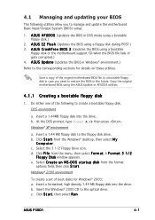
... t a r t u p d i s k from the format options field, then click S t a r t. Insert the Windows® 2000 CD to the floppy disk drive. A S U S C r a s h F r e e B I O S 2 (Updates the BIOS using the ASUS Update or AFUDOS utilities. 4.1.1 Creating a bootable floppy disk 1. Save a copy of the original motherboard BIOS file to a bootable floppy disk in case you to manage... disk. A S U S E Z F l a s h (Updates the BIOS using a bootable floppy disk.) 2. b. b. Select the 3 1/2 Floppy Drive icon. e. Insert a formatted, high density 1.44 MB floppy disk into the drive. ASUS P5GD1 4-1
... t a r t u p d i s k from the format options field, then click S t a r t. Insert the Windows® 2000 CD to the floppy disk drive. A S U S C r a s h F r e e B I O S 2 (Updates the BIOS using the ASUS Update or AFUDOS utilities. 4.1.1 Creating a bootable floppy disk 1. Save a copy of the original motherboard BIOS file to a bootable floppy disk in case you to manage... disk. A S U S E Z F l a s h (Updates the BIOS using a bootable floppy disk.) 2. b. b. Select the 3 1/2 Floppy Drive icon. e. Insert a formatted, high density 1.44 MB floppy disk into the drive. ASUS P5GD1 4-1
P5GD1 User's Manual English Version E1745
Page 70
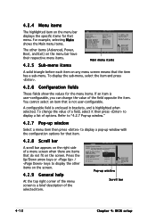
... an item is userconfigurable, you can change the value of the field opposite the item. A configurable field is enclosed in ] [English] :[ST320413A] :[ASUS CD-S340] :[Not Detected] :[Not Detected] :[Not Detected] :[Not Detected] Main menu items Use [ENTER], [TAB] or [SHIFT-TAB] to ... DRAM Idle Timer DRAm Refresh Rate [Enabled] [Auto] [Auto] [Auto] Graphic Adapter Priority Graphics Aperture Size Spread Spectrum [AGP/PCI] [ 64 MB] [Enabled] ICH Delayed Transaction [Enabled] MPS Revision [1.4] Select Screen Select Item +- Press the Up/Down arrow keys or / keys to display a...
... an item is userconfigurable, you can change the value of the field opposite the item. A configurable field is enclosed in ] [English] :[ST320413A] :[ASUS CD-S340] :[Not Detected] :[Not Detected] :[Not Detected] :[Not Detected] Main menu items Use [ENTER], [TAB] or [SHIFT-TAB] to ... DRAM Idle Timer DRAm Refresh Rate [Enabled] [Auto] [Auto] [Auto] Graphic Adapter Priority Graphics Aperture Size Spread Spectrum [AGP/PCI] [ 64 MB] [Enabled] ICH Delayed Transaction [Enabled] MPS Revision [1.4] Select Screen Select Item +- Press the Up/Down arrow keys or / keys to display a...
P5GD1 User's Manual English Version E1745
Page 91
.... When using a 4-pin CPU fan cable. CPU Q-Fan Control [Disabled] Allows you enable the C P U Q - F a n C o n t r o l feature. ASUS P5GD1 4-33 If the fan is not connected to [DC] when using a 3-pin CPU fan cable. F a n C o n t r o l items appear when you to [PWM...]. Change Option F1 General Help F10 Save and Exit ESC Exit CPU Temperature [xxxC/xxxF] MB Temperature [xxxC/xxxF] The onboard hardware monitor automatically detects and displays the motherboard and CPU temperatures. Configuration options: [PWM] [DC] Some CPU fans ...
.... When using a 4-pin CPU fan cable. CPU Q-Fan Control [Disabled] Allows you enable the C P U Q - F a n C o n t r o l feature. ASUS P5GD1 4-33 If the fan is not connected to [DC] when using a 3-pin CPU fan cable. F a n C o n t r o l items appear when you to [PWM...]. Change Option F1 General Help F10 Save and Exit ESC Exit CPU Temperature [xxxC/xxxF] MB Temperature [xxxC/xxxF] The onboard hardware monitor automatically detects and displays the motherboard and CPU temperatures. Configuration options: [PWM] [DC] Some CPU fans ...

P5GD1 User's Manual English Version E1745
Page 123
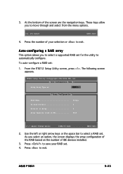
... to select a supported RAID set for the utility to select a RAID set. Press to move through and select from the menu options. [1]..[5] Select [ESC] Exit 4. ASUS P5GD1 5-23 Press to save your selection or to exit. To auto-configure a RAID set . 4. The following screen appears. These keys allow you select an option...-2004 ITE, Inc. [ Auto Configuration Menu ] Setup Array Type as: RAID 0 [ Array Configuration ] RAID Mode Un-used Drive(s Drive(s) in Array Array Capacity (size in MB Stripe 4 0 8056 [→,←,Space] Change Option [CTRL-Y] Save [ESC] Exit 2.
... to select a supported RAID set for the utility to select a RAID set. Press to move through and select from the menu options. [1]..[5] Select [ESC] Exit 4. ASUS P5GD1 5-23 Press to save your selection or to exit. To auto-configure a RAID set . 4. The following screen appears. These keys allow you select an option...-2004 ITE, Inc. [ Auto Configuration Menu ] Setup Array Type as: RAID 0 [ Array Configuration ] RAID Mode Un-used Drive(s Drive(s) in Array Array Capacity (size in MB Stripe 4 0 8056 [→,←,Space] Change Option [CTRL-Y] Save [ESC] Exit 2.
P5GD1 User's Manual English Version E1745
Page 124
...Setup Utility (C)Copyright 2002-2004 ITE, Inc. [ Define RAID Menu ] Array No Array 0 Array 1 Array 2 Array 3 Array Mode Drive No Size(MB Status ∗ : Capacity (GB) [↑] Up [↓] Down [Space] Boot Array ♦ : Bootable Array [Enter] Select [ESC] Exit ...Stripe 64KB Drive No 4 Status Functional Channel ID Drive Name Pri/D0 XXXXXXXXXXXXXX Pri/D1 XXXXXXXXXXXXXX Sec/D0 XXXXXXXXXXXXXX Sec/D1 XXXXXXXXXXXXXX [ Drive Assignments] Size(MB) XXXXXX XXXXXX XXXXXX XXXXXX Assignment Y Y Y Y ∗ : Capacity (GB) [↑] Up [↓] Down [Space] Change Option [Ctrl...
...Setup Utility (C)Copyright 2002-2004 ITE, Inc. [ Define RAID Menu ] Array No Array 0 Array 1 Array 2 Array 3 Array Mode Drive No Size(MB Status ∗ : Capacity (GB) [↑] Up [↓] Down [Space] Boot Array ♦ : Bootable Array [Enter] Select [ESC] Exit ...Stripe 64KB Drive No 4 Status Functional Channel ID Drive Name Pri/D0 XXXXXXXXXXXXXX Pri/D1 XXXXXXXXXXXXXX Sec/D0 XXXXXXXXXXXXXX Sec/D1 XXXXXXXXXXXXXX [ Drive Assignments] Size(MB) XXXXXX XXXXXX XXXXXX XXXXXX Assignment Y Y Y Y ∗ : Capacity (GB) [↑] Up [↓] Down [Space] Change Option [Ctrl...
P5GD1 User's Manual English Version E1745
Page 125
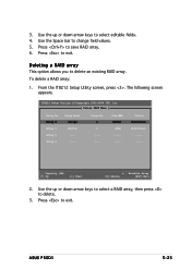
... Utility (C)Copyright 2002-2004 ITE, Inc. [ Delete RAID Menu ] Array No Array 0 Array 1 Array 2 Array 3 Array Mode Stripe Mirror ------- ASUS P5GD1 5-25 Use the up or down arrow keys to select a RAID array, then press to delete. 3. To delete a RAID array: 1. 3. From ...Status Functional Functional --------- ∗ : Capacity (GB) [↑] Up [↓] Down ♦ : Bootable Array [D] Delete [ESC] Exit 2. Size(MB) XXXXXX XXXX --------- Use the up or down arrow keys to change field values. 5. The following screen appears. Use the Space bar to select editable...
... Utility (C)Copyright 2002-2004 ITE, Inc. [ Delete RAID Menu ] Array No Array 0 Array 1 Array 2 Array 3 Array Mode Stripe Mirror ------- ASUS P5GD1 5-25 Use the up or down arrow keys to select a RAID array, then press to delete. 3. To delete a RAID array: 1. 3. From ...Status Functional Functional --------- ∗ : Capacity (GB) [↑] Up [↓] Down ♦ : Bootable Array [D] Delete [ESC] Exit 2. Size(MB) XXXXXX XXXX --------- Use the up or down arrow keys to change field values. 5. The following screen appears. Use the Space bar to select editable...
P5GD1 User's Manual English Version E1745
Page 126
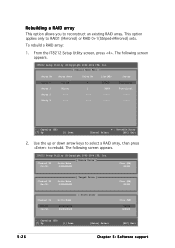
... : Bootable Array [Enter] Select [ESC] Exit 2. The following screen appears. Channel ID Pri/D1 [ Source Drive ] Drive Name XXXXXXXXXX Size (MB) XXXXX Channel ID Sec/D1 Drive Name XXXXXXXXXX [ Target Drive ] Channel ID Pri/D1 Sec/D1 Drive Name XXXXXXXXXX XXXXXXXXXX [ Drive List] Size... (MB) XXXXX Size (MB) XXXXX XXXXXX ∗ : Capacity (GB) [↑] Up [↓] Down [Enter] Select [ESC] Exit 5-26 Chapter 5: Software support Rebuilding ...
... : Bootable Array [Enter] Select [ESC] Exit 2. The following screen appears. Channel ID Pri/D1 [ Source Drive ] Drive Name XXXXXXXXXX Size (MB) XXXXX Channel ID Sec/D1 Drive Name XXXXXXXXXX [ Target Drive ] Channel ID Pri/D1 Sec/D1 Drive Name XXXXXXXXXX XXXXXXXXXX [ Drive List] Size... (MB) XXXXX Size (MB) XXXXX XXXXXX ∗ : Capacity (GB) [↑] Up [↓] Down [Enter] Select [ESC] Exit 5-26 Chapter 5: Software support Rebuilding ...
P5GD1 User's Manual English Version E1745
Page 127
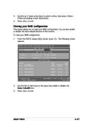
.../D0 XXXXXXXXXXXXXX [ Drive Status ] Size (MB) XXXXXX Array No Array 0 Drive Mode U5 Pri/D1 XXXXXXXXXXXXXX XXXXXX Array 0 U2 Sec/D0 XXXXXXXXXXXXXX XXXXXX Array 0 U4 Sec/D1 XXXXXXXXXXXXXX XXXXXX Array 0 U6 ∗ : Capacity (GB) [→,←,Space] Change Option Drive Mode: P = PIO, D = DMA, U = UDMA [ESC] Exit 3. ASUS P5GD1 5-27 To view your RAID...
.../D0 XXXXXXXXXXXXXX [ Drive Status ] Size (MB) XXXXXX Array No Array 0 Drive Mode U5 Pri/D1 XXXXXXXXXXXXXX XXXXXX Array 0 U2 Sec/D0 XXXXXXXXXXXXXX XXXXXX Array 0 U4 Sec/D1 XXXXXXXXXXXXXX XXXXXX Array 0 U6 ∗ : Capacity (GB) [→,←,Space] Change Option Drive Mode: P = PIO, D = DMA, U = UDMA [ESC] Exit 3. ASUS P5GD1 5-27 To view your RAID...
P5GD1 User's Manual English Version E1673
Page 12
xii P5GD1 specifications summary BIOS features Rear panel Internal connectors Power Requirement Form Factor Support CD contents 4 MB Flash ROM, AMI BIOS, PnP, DMI2.0, SM BIOS 2.3, WfM2.0 1 x Parallel port 1 x LAN (RJ-45) port 1 x Rear speaker out port 1 x Side speaker out port 1 x Line In ... ATX power supply (with 24-pin and 4-pin 12 V plugs) ATX 12 V 2.0 compliant ATX form factor: 12 in x 9.6 in (30.5 cm x 24.4 cm) Device drivers ASUS PC Probe ASUS Live Update utility Anti-virus software (OEM version) *Specifications are subject to change without notice.
xii P5GD1 specifications summary BIOS features Rear panel Internal connectors Power Requirement Form Factor Support CD contents 4 MB Flash ROM, AMI BIOS, PnP, DMI2.0, SM BIOS 2.3, WfM2.0 1 x Parallel port 1 x LAN (RJ-45) port 1 x Rear speaker out port 1 x Side speaker out port 1 x Line In ... ATX power supply (with 24-pin and 4-pin 12 V plugs) ATX 12 V 2.0 compliant ATX form factor: 12 in x 9.6 in (30.5 cm x 24.4 cm) Device drivers ASUS PC Probe ASUS Live Update utility Anti-virus software (OEM version) *Specifications are subject to change without notice.
P5GD1 User's Manual English Version E1673
Page 16
...-pin surface mount Land Grid Array (LGA) socket designed for thinner, more flexible cables with 800 MHz Front Side Bus (FSB), 1 MB L2 cache, and core speed of up to 3.6 GHz. The Intel® 915P GMCH platform is software compatible with 533/800MHz front side... processor in packets. The motherboard supports the Intel® Pentium® 4 processor with lower pin count, reduced voltage requirement, and up to 150 MB/s data transfer rate. 1-2 Chapter 1: Product introduction Dual-channel DDR memory support Employing the Double Data Rate (DDR) memory technology, the motherboard supports...
...-pin surface mount Land Grid Array (LGA) socket designed for thinner, more flexible cables with 800 MHz Front Side Bus (FSB), 1 MB L2 cache, and core speed of up to 3.6 GHz. The Intel® 915P GMCH platform is software compatible with 533/800MHz front side... processor in packets. The motherboard supports the Intel® Pentium® 4 processor with lower pin count, reduced voltage requirement, and up to 150 MB/s data transfer rate. 1-2 Chapter 1: Product introduction Dual-channel DDR memory support Employing the Double Data Rate (DDR) memory technology, the motherboard supports...

P5GD1 User's Manual English Version E1673
Page 32
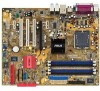
... to chipset limitation, 128MB DDR DIMMs are not supported in this section. • Installing DDR DIMMs other than the recommended configurations may install 256 MB, 512 MB and 1 GB unbuffered non-ECC DDR DIMMs into the DIMM sockets using the memory configurations in Table 1. • In dual-channel configurations, install... four 184-pin Double Data Rate (DDR) Dual Inline Memory Modules (DIMM) sockets. Use any of the sockets: DIMM_A1 DIMM_A2 DIMM_B1 DIMM_B2 P5GD1 P5GD1 184-Pin DDR DIMM Sockets 2.4.2 Memory Configurations You may cause memory sizing error or system boot failure.
... to chipset limitation, 128MB DDR DIMMs are not supported in this section. • Installing DDR DIMMs other than the recommended configurations may install 256 MB, 512 MB and 1 GB unbuffered non-ECC DDR DIMMs into the DIMM sockets using the memory configurations in Table 1. • In dual-channel configurations, install... four 184-pin Double Data Rate (DDR) Dual Inline Memory Modules (DIMM) sockets. Use any of the sockets: DIMM_A1 DIMM_A2 DIMM_B1 DIMM_B2 P5GD1 P5GD1 184-Pin DDR DIMM Sockets 2.4.2 Memory Configurations You may cause memory sizing error or system boot failure.
P5GD1 User's Manual English Version E1673
Page 49
... Ground +5 Volts Ground +3 Volts +3 Volts Ground +5 Volts +5 Volts +5 Volts -5 Volts Ground Ground Ground PSON# Ground -12 Volts +3 Volts ASUS P5GD1 2-29 otherwise, the system will not boot up if the power is recommended that the PSU has a minimum power rating of 300 W. This PSU type... : Memory : Grpahics card : Parallel ATA devices : Serial ATA device : Optical drives : SCSI devices : Intel® Pentium® 4 3.6 GHz 512 MB DDR (x 4) PCI Express x16 Nvidia EN5900 IDE hard disk drive (x 2) SATA hard disk drive CD-ROM (x 2) SCSI card and SCSI hard disk drive ...
... Ground +5 Volts Ground +3 Volts +3 Volts Ground +5 Volts +5 Volts +5 Volts -5 Volts Ground Ground Ground PSON# Ground -12 Volts +3 Volts ASUS P5GD1 2-29 otherwise, the system will not boot up if the power is recommended that the PSU has a minimum power rating of 300 W. This PSU type... : Memory : Grpahics card : Parallel ATA devices : Serial ATA device : Optical drives : SCSI devices : Intel® Pentium® 4 3.6 GHz 512 MB DDR (x 4) PCI Express x16 Nvidia EN5900 IDE hard disk drive (x 2) SATA hard disk drive CD-ROM (x 2) SCSI card and SCSI hard disk drive ...
P5GD1 User's Manual English Version E1673
Page 59
... the original motherboard BIOS using a bootable floppy disk or the motherboard support CD when the BIOS file fails or gets corrupted.) 4. Windows® XP environment a. e. ASUS P5GD1 4-1 A F o r m a t 3 1 / 2 F l o p p y D i s k window appears. Click S t a r t, then select R u n. A S U S U p d a t e (Updates the BIOS in DOS mode using a floppy disk during POST.) 3. c. D O ... details on these utilities. At the DOS prompt, type format A:/S then press . Insert a 1.44 MB floppy disk to the optical drive. b. d. Windows® 2000 environment To create a set of the...
... the original motherboard BIOS using a bootable floppy disk or the motherboard support CD when the BIOS file fails or gets corrupted.) 4. Windows® XP environment a. e. ASUS P5GD1 4-1 A F o r m a t 3 1 / 2 F l o p p y D i s k window appears. Click S t a r t, then select R u n. A S U S U p d a t e (Updates the BIOS in DOS mode using a floppy disk during POST.) 3. c. D O ... details on these utilities. At the DOS prompt, type format A:/S then press . Insert a 1.44 MB floppy disk to the optical drive. b. d. Windows® 2000 environment To create a set of the...
P5GD1 User's Manual English Version E1673
Page 70
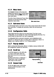
... Idle Timer DRAm Refresh Rate [Enabled] [Auto] [Auto] [Auto] Graphic Adapter Priority Graphics Aperture Size Spread Spectrum [AGP/PCI] [ 64 MB] [Enabled] ICH Delayed Transaction [Enabled] MPS Revision [1.4] Select Screen Select Item +- A configurable field is a brief description of options. Change ... A scroll bar appears on the screen. 4.2.9 General help At the top right corner of the menu screen is enclosed in ] [English] :[ST320413A] :[ASUS CD-S340] :[Not Detected] :[Not Detected] :[Not Detected] :[Not Detected] Use [ENTER], [TAB] or [SHIFT-TAB] to display the other items...
... Idle Timer DRAm Refresh Rate [Enabled] [Auto] [Auto] [Auto] Graphic Adapter Priority Graphics Aperture Size Spread Spectrum [AGP/PCI] [ 64 MB] [Enabled] ICH Delayed Transaction [Enabled] MPS Revision [1.4] Select Screen Select Item +- A configurable field is a brief description of options. Change ... A scroll bar appears on the screen. 4.2.9 General help At the top right corner of the menu screen is enclosed in ] [English] :[ST320413A] :[ASUS CD-S340] :[Not Detected] :[Not Detected] :[Not Detected] :[Not Detected] Use [ENTER], [TAB] or [SHIFT-TAB] to display the other items...

P5GD1 User's Manual English Version E1673
Page 91
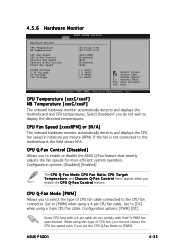
Configuration options: [PWM] [DC] ASUS P5GD1 4-33 Change Option F1 General Help F10 Save and Exit ESC Exit CPU Temperature [xxxC/xxxF] MB Temperature [xxxC/xxxF] The onboard hardware monitor automatically detects and displays the motherboard and CPU temperatures. If the fan is set to... the motherboard, the field shows N/A. CPU Q-Fan Control [Disabled] Allows you do not wish to enable or disable the ASUS Q-Fan feature that...
Configuration options: [PWM] [DC] ASUS P5GD1 4-33 Change Option F1 General Help F10 Save and Exit ESC Exit CPU Temperature [xxxC/xxxF] MB Temperature [xxxC/xxxF] The onboard hardware monitor automatically detects and displays the motherboard and CPU temperatures. If the fan is set to... the motherboard, the field shows N/A. CPU Q-Fan Control [Disabled] Allows you do not wish to enable or disable the ASUS Q-Fan feature that...
P5GD1 User's Manual English Version E1673
Page 123
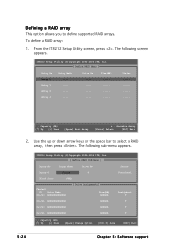
... array This option allows you to exit. Press to save your selection or to move through and select from the menu options. [1]..[5] Select [ESC] Exit 4. ASUS P5GD1 5-23 At the bottom of IDE devices installed. 3. To auto-configure a RAID set . 4. Press the number of your RAID set : 1. As you select an ... ITE, Inc. [ Auto Configuration Menu ] Setup Array Type as: RAID 0 [ Array Configuration ] RAID Mode Un-used Drive(s Drive(s) in Array Array Capacity (size in MB Stripe 4 0 8056 [→,←,Space] Change Option [CTRL-Y] Save [ESC] Exit 2. 3.
... array This option allows you to exit. Press to save your selection or to move through and select from the menu options. [1]..[5] Select [ESC] Exit 4. ASUS P5GD1 5-23 At the bottom of IDE devices installed. 3. To auto-configure a RAID set . 4. Press the number of your RAID set : 1. As you select an ... ITE, Inc. [ Auto Configuration Menu ] Setup Array Type as: RAID 0 [ Array Configuration ] RAID Mode Un-used Drive(s Drive(s) in Array Array Capacity (size in MB Stripe 4 0 8056 [→,←,Space] Change Option [CTRL-Y] Save [ESC] Exit 2. 3.


