
User Manual
Page 1
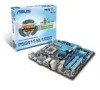
Motherboard P5G41T-M/USB3
Motherboard P5G41T-M/USB3

User Manual
Page 3
Contents Notices...vi Safety information vii About this guide vii P5G41T-M/USB3 specifications summary ix Chapter 1: Product introduction 1.1 Welcome 1-1 1.2 Package contents 1-1 1.3 Special features 1-1 1.3.1 Product highlights 1-1 1.3.2 Innovative ASUS features 1-3 1.4 Before you proceed 1-5 1.5 Motherboard overview 1-6 1.5.1 Placement direction 1-6 1.5.2 Screw holes 1-6 1.5.3 Motherboard layout 1-7 1.5.4 Layout contents 1-7 1.6 Central Processing Unit (CPU 1-8 1.6.1 Installing the CPU 1-8 1.6.2 Installing the CPU heatsink and fan 1-11 1.6.3 Uninstalling...
Contents Notices...vi Safety information vii About this guide vii P5G41T-M/USB3 specifications summary ix Chapter 1: Product introduction 1.1 Welcome 1-1 1.2 Package contents 1-1 1.3 Special features 1-1 1.3.1 Product highlights 1-1 1.3.2 Innovative ASUS features 1-3 1.4 Before you proceed 1-5 1.5 Motherboard overview 1-6 1.5.1 Placement direction 1-6 1.5.2 Screw holes 1-6 1.5.3 Motherboard layout 1-7 1.5.4 Layout contents 1-7 1.6 Central Processing Unit (CPU 1-8 1.6.1 Installing the CPU 1-8 1.6.2 Installing the CPU heatsink and fan 1-11 1.6.3 Uninstalling...
User Manual
Page 6
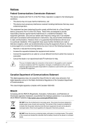
... to assure compliance with Canadian ICES-003. REACH Complying with the limits for help. If this equipment. DO NOT throw the motherboard in a particular installation. This equipment has been tested and found to provide reasonable protection against harmful interference in municipal waste. These... of shielded cables for radio noise emissions from that the battery should not be placed in our products at ASUS REACH website at http://green.asus.com/english/REACH.htm. Canadian Department of Communications Statement This digital apparatus does not exceed the Class B limits...
... to assure compliance with Canadian ICES-003. REACH Complying with the limits for help. If this equipment. DO NOT throw the motherboard in a particular installation. This equipment has been tested and found to provide reasonable protection against harmful interference in municipal waste. These... of shielded cables for radio noise emissions from that the battery should not be placed in our products at ASUS REACH website at http://green.asus.com/english/REACH.htm. Canadian Department of Communications Statement This digital apparatus does not exceed the Class B limits...
User Manual
Page 7
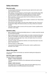
..., disconnect all power cables from the existing system before you add a device. • Before connecting or removing signal cables from the motherboard, ensure that all cables are correctly connected and the power cables are not damaged. These devices could interrupt the grounding circuit. •...power supply is organized This guide contains the following parts: • Chapter 1: Product introduction This chapter describes the features of the motherboard and the new technology it may become wet. • Place the product on it by yourself. Detailed descriptions of the electrical ...
..., disconnect all power cables from the existing system before you add a device. • Before connecting or removing signal cables from the motherboard, ensure that all cables are correctly connected and the power cables are not damaged. These devices could interrupt the grounding circuit. •...power supply is organized This guide contains the following parts: • Chapter 1: Product introduction This chapter describes the features of the motherboard and the new technology it may become wet. • Place the product on it by yourself. Detailed descriptions of the electrical ...
User Manual
Page 11
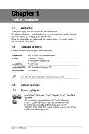
...list below. 1.2 Package contents Check your motherboard package for the following items. Motherboard Cables Accessories Application DVD Documentation ASUS P5G41T-M/USB3 motherboard 2 x Serial ATA cables 1 x Ultra DMA 100/66/33 cable 1 x I/O shield ASUS motherboard support DVD User Manual If any of ...it , check the items in your package with 1333/1066/800MHz FSB. ASUS P5G41T-M/USB3 1-1 The motherboard delivers a host of ASUS quality motherboards! Thank you start installing the motherboard, and hardware devices on it another standout in the 45nm manufacturing process. Chapter...
...list below. 1.2 Package contents Check your motherboard package for the following items. Motherboard Cables Accessories Application DVD Documentation ASUS P5G41T-M/USB3 motherboard 2 x Serial ATA cables 1 x Ultra DMA 100/66/33 cable 1 x I/O shield ASUS motherboard support DVD User Manual If any of ...it , check the items in your package with 1333/1066/800MHz FSB. ASUS P5G41T-M/USB3 1-1 The motherboard delivers a host of ASUS quality motherboards! Thank you start installing the motherboard, and hardware devices on it another standout in the 45nm manufacturing process. Chapter...
User Manual
Page 12
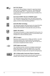
... without converting it to analog format and keeps the best signal quality. 100% All High-quality Conductive Polymer Capacitors This motherboard uses high-quality conductive polymer capacitors for advanced operating systems. USB 3.0 support Experience ultra-fast data transfer at 4.8Gbps ... enhanced scalability and doubling the bus bandwidth for 3D graphics and other memory-demanding applications. S/PDIF digital sound ready This motherboard provides convenient connectivity to external home theater audio systems via coaxial and optical S/PDIF_OUT (SONYPHILIPS Digital Interface) jacks. Built...
... without converting it to analog format and keeps the best signal quality. 100% All High-quality Conductive Polymer Capacitors This motherboard uses high-quality conductive polymer capacitors for advanced operating systems. USB 3.0 support Experience ultra-fast data transfer at 4.8Gbps ... enhanced scalability and doubling the bus bandwidth for 3D graphics and other memory-demanding applications. S/PDIF digital sound ready This motherboard provides convenient connectivity to external home theater audio systems via coaxial and optical S/PDIF_OUT (SONYPHILIPS Digital Interface) jacks. Built...
User Manual
Page 13
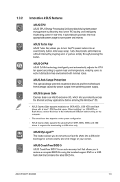
... into an overclocking button. ASUS CrashFree BIOS 3 ASUS CrashFree BIOS 3 is an ASUS exclusive OS, which lets you to the motherboard USB port before entering the Windows® OS. • ASUS Express Gate supports installation on the system configuration. • ASUS Express Gate supports file uploading from switching power supply. ASUS P5G41T-M/USB3 1-3 1.3.2 Innovative ASUS features ASUS EPU ASUS EPU (Energy Processing...
... into an overclocking button. ASUS CrashFree BIOS 3 ASUS CrashFree BIOS 3 is an ASUS exclusive OS, which lets you to the motherboard USB port before entering the Windows® OS. • ASUS Express Gate supports installation on the system configuration. • ASUS Express Gate supports file uploading from switching power supply. ASUS P5G41T-M/USB3 1-3 1.3.2 Innovative ASUS features ASUS EPU ASUS EPU (Energy Processing...
User Manual
Page 14
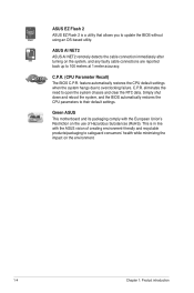
... the CPU parameters to update the BIOS without using an OS-based utility. Green ASUS This motherboard and its packaging comply with the ASUS vision of Hazardous Substances (RoHS). ASUS EZ Flash 2 ASUS EZ Flash 2 is in line with the European Union's Restriction on the use ...clear the RTC data. eliminates the need to overclocking failure. This is a utility that allows you to their default settings. ASUS AI NET2 ASUS AI NET2 remotely detects the cable connection immediately after turning on the environment. 1-4 Chapter 1: Product introduction C.P.R. C.P.R. (CPU Parameter Recall)...
... the CPU parameters to update the BIOS without using an OS-based utility. Green ASUS This motherboard and its packaging comply with the ASUS vision of Hazardous Substances (RoHS). ASUS EZ Flash 2 ASUS EZ Flash 2 is in line with the European Union's Restriction on the use ...clear the RTC data. eliminates the need to overclocking failure. This is a utility that allows you to their default settings. ASUS AI NET2 ASUS AI NET2 remotely detects the cable connection immediately after turning on the environment. 1-4 Chapter 1: Product introduction C.P.R. C.P.R. (CPU Parameter Recall)...
User Manual
Page 15
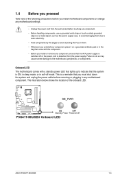
... OFF Standby Power Powered Off P5G41T-M/USB3 Onboard LED ASUS P5G41T-M/USB3 1-5 The illustration below shows the location of the following precautions before removing or plugging in any motherboard component. This is detached from the wall socket before touching any component. • Before handling components, use ... static electricity. • Hold components by the edges to avoid touching the ICs on them. • Whenever you uninstall any motherboard settings. • Unplug the power cord from the power supply. 1.4 Before you proceed Take note of the onboard LED. Failure...
... OFF Standby Power Powered Off P5G41T-M/USB3 Onboard LED ASUS P5G41T-M/USB3 1-5 The illustration below shows the location of the following precautions before removing or plugging in any motherboard component. This is detached from the wall socket before touching any component. • Before handling components, use ... static electricity. • Hold components by the edges to avoid touching the ICs on them. • Whenever you uninstall any motherboard settings. • Unplug the power cord from the power supply. 1.4 Before you proceed Take note of the onboard LED. Failure...
User Manual
Page 16
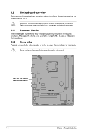
... it. Place this side towards the rear of the chassis P5G41T-M/USB3 1-6 Chapter 1: Product introduction Do not overtighten the screws! Failure to do so can damage the motherboard. Doing so can cause you physical injury and damage motherboard components. 1.5.1 Placement direction When installing the motherboard, ensure that you unplug the power cord before installing or...
... it. Place this side towards the rear of the chassis P5G41T-M/USB3 1-6 Chapter 1: Product introduction Do not overtighten the screws! Failure to do so can damage the motherboard. Doing so can cause you physical injury and damage motherboard components. 1.5.1 Placement direction When installing the motherboard, ensure that you unplug the power cord before installing or...
User Manual
Page 17
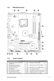
...21 9. LPT connector (26-1 pin LPT) 1-23 1-24 12. Serial port connector (10-1 pin COM1) 1-26 ASUS P5G41T-M/USB3 1-7 USB connectors (10-1 pin USB56, USB78) 1-26 1-13 11. Digital audio connector (4-1 pin SPDIF_OUT) 1-21 1-...Motherboard layout 1 2 3 20.8cm(8.2in) KBMS ATX12V HDMI 4 2 CPU_FAN DDR3 DIMM_A1 (64bit, 240-pin module) DDR3 DIMM_B1 (64bit, 240-pin module) PRI_IDE VGA LGA775 NEC 5 USB 3.0 USB_3_12 24.4cm(9.6in) LAN1_USB12 RTL 8111E CHA_FAN SPDIF_O2 AUDIO ICS 954 A4 COM1 PCIEX1_1 Intel® G41 Lithium Cell CMOS Power Super I/O PCIEX16 P5G41T-M/USB3...
...21 9. LPT connector (26-1 pin LPT) 1-23 1-24 12. Serial port connector (10-1 pin COM1) 1-26 ASUS P5G41T-M/USB3 1-7 USB connectors (10-1 pin USB56, USB78) 1-26 1-13 11. Digital audio connector (4-1 pin SPDIF_OUT) 1-21 1-...Motherboard layout 1 2 3 20.8cm(8.2in) KBMS ATX12V HDMI 4 2 CPU_FAN DDR3 DIMM_A1 (64bit, 240-pin module) DDR3 DIMM_B1 (64bit, 240-pin module) PRI_IDE VGA LGA775 NEC 5 USB 3.0 USB_3_12 24.4cm(9.6in) LAN1_USB12 RTL 8111E CHA_FAN SPDIF_O2 AUDIO ICS 954 A4 COM1 PCIEX1_1 Intel® G41 Lithium Cell CMOS Power Super I/O PCIEX16 P5G41T-M/USB3...
User Manual
Page 18
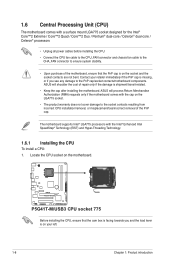
...socket. • The product warranty does not cover damage to the PnP cap/socket contacts/motherboard components. ASUS will process Return Merchandise Authorization (RMA) requests only if the motherboard comes with the Intel® Enhanced Intel SpeedStep® Technology (EIST) and Hyper-Threading Technology...CPU To install a CPU: 1. ASUS will shoulder the cost of the motherboard, ensure that the cam box is facing towards you and the load lever is on your retailer immediately if the PnP cap is on the motherboard. P5G41T-M/USB3 P5G41T-M/USB3 CPU socket 775 Before installing the ...
...socket. • The product warranty does not cover damage to the PnP cap/socket contacts/motherboard components. ASUS will process Return Merchandise Authorization (RMA) requests only if the motherboard comes with the Intel® Enhanced Intel SpeedStep® Technology (EIST) and Hyper-Threading Technology...CPU To install a CPU: 1. ASUS will shoulder the cost of the motherboard, ensure that the cam box is facing towards you and the load lever is on your retailer immediately if the PnP cap is on the motherboard. P5G41T-M/USB3 P5G41T-M/USB3 CPU socket 775 Before installing the ...
User Manual
Page 21
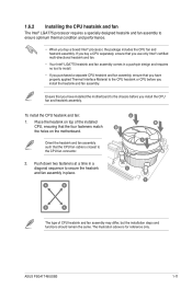
...; When you install the heatsink and fan assembly. ASUS P5G41T-M/USB3 1-11 Ensure that the four fasteners match the holes on top of CPU heatsink and fan assembly may differ, but the installation steps and functions should remain the same. Place the heatsink on the motherboard. The illustration above is closest to the CPU...
...; When you install the heatsink and fan assembly. ASUS P5G41T-M/USB3 1-11 Ensure that the four fasteners match the holes on top of CPU heatsink and fan assembly may differ, but the installation steps and functions should remain the same. Place the heatsink on the motherboard. The illustration above is closest to the CPU...
User Manual
Page 22
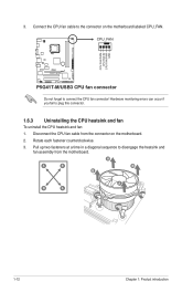
...on the motherboard labeled CPU_FAN. Hardware monitoring errors can occur if you fail to connect the CPU fan connector! A A B B B A B A 1-12 Chapter 1: Product introduction 3. CPU_FAN CPU FAN PWM CPU FAN IN CPU FAN PWR GND P5G41T-M/USB3 P5G41T-M/USB3 CPU fan... connector Do not forget to plug this connector. 1.6.3 Uninstalling the CPU heatsink and fan To uninstall the CPU heatsink and fan: 1. Disconnect the CPU fan cable from the motherboard. Rotate each fastener counterclockwise. 3.
...on the motherboard labeled CPU_FAN. Hardware monitoring errors can occur if you fail to connect the CPU fan connector! A A B B B A B A 1-12 Chapter 1: Product introduction 3. CPU_FAN CPU FAN PWM CPU FAN IN CPU FAN PWR GND P5G41T-M/USB3 P5G41T-M/USB3 CPU fan... connector Do not forget to plug this connector. 1.6.3 Uninstalling the CPU heatsink and fan To uninstall the CPU heatsink and fan: 1. Disconnect the CPU fan cable from the motherboard. Rotate each fastener counterclockwise. 3.
User Manual
Page 23
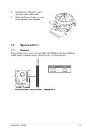
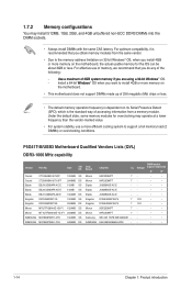
Carefully remove the heatsink and fan assembly from the motherboard. 5. Rotate each fastener clockwise to ensure correct orientation when reinstalling. 1.7 System memory 1.7.1 Overview The motherboard comes with two Double Data Rate 3 (DDR3) Dual Inline Memory Modules (DIMM) sockets. 4. The figure illustrates the location of the DDR3 DIMM sockets: DIMM_A1 DIMM_B1 Channel Channel A Channel B Sockets DIMM_A1 DIMM_B1 P5G41T-M/USB3 P5G41T-M/USB3 240-pin DDR3 DIMM sockets ASUS P5G41T-M/USB3 1-13
Carefully remove the heatsink and fan assembly from the motherboard. 5. Rotate each fastener clockwise to ensure correct orientation when reinstalling. 1.7 System memory 1.7.1 Overview The motherboard comes with two Double Data Rate 3 (DDR3) Dual Inline Memory Modules (DIMM) sockets. 4. The figure illustrates the location of the DDR3 DIMM sockets: DIMM_A1 DIMM_B1 Channel Channel A Channel B Sockets DIMM_A1 DIMM_B1 P5G41T-M/USB3 P5G41T-M/USB3 240-pin DDR3 DIMM sockets ASUS P5G41T-M/USB3 1-13
User Manual
Page 24
P5G41T-M/USB3 Motherboard Qualified Vendors Lists (QVL) DDR3-1066 MHz capability Vendor Part No. DIMM socket CL Voltage support (Optional) A*...memory address limitation on 32-bit Windows® OS, when you install 4GB or more memory on the motherboard. • This motherboard does not support DIMMs made up of 256 megabits (Mb) chips or less. • The default... memory operation frequency is dependent on the motherboard, the actual usable memory for overclocking may install 512MB, 1GB, 2GB, and 4GB unbuffered non‑ECC...
P5G41T-M/USB3 Motherboard Qualified Vendors Lists (QVL) DDR3-1066 MHz capability Vendor Part No. DIMM socket CL Voltage support (Optional) A*...memory address limitation on 32-bit Windows® OS, when you install 4GB or more memory on the motherboard. • This motherboard does not support DIMMs made up of 256 megabits (Mb) chips or less. • The default... memory operation frequency is dependent on the motherboard, the actual usable memory for overclocking may install 512MB, 1GB, 2GB, and 4GB unbuffered non‑ECC...
User Manual
Page 26
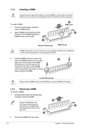
... a DIMM into the socket VERTICALLY to both ends of the DIMM. The DIMM might get damaged when it fits in any further to both the motherboard and the components. Remove the DIMM from the socket. 1-16 2 1 Chapter 1: Product introduction 1.7.3 Installing a DIMM Unplug the power supply before adding or removing DIMMs or...
... a DIMM into the socket VERTICALLY to both ends of the DIMM. The DIMM might get damaged when it fits in any further to both the motherboard and the components. Remove the DIMM from the socket. 1-16 2 1 Chapter 1: Product introduction 1.7.3 Installing a DIMM Unplug the power supply before adding or removing DIMMs or...
User Manual
Page 27
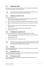
...the screw for the expansion card. Assign an IRQ to the chassis with the PCI Express specifications. 1.8.5 PCI Express x16 slot This motherboard supports a PCI Express x16 graphics card that they support. Turn on shared slots, ensure that the drivers support "Share IRQ" or ... Express specifications. Remove the system unit cover (if your motherboard is completely seated on BIOS setup. 2. The following sub‑sections describe the slots and the expansion cards that complies with it by adjusting the software settings. 1. Secure the card to the card. 3. ASUS P5G41T-M/USB3 1-17
...the screw for the expansion card. Assign an IRQ to the chassis with the PCI Express specifications. 1.8.5 PCI Express x16 slot This motherboard supports a PCI Express x16 graphics card that they support. Turn on shared slots, ensure that the drivers support "Share IRQ" or ... Express specifications. Remove the system unit cover (if your motherboard is completely seated on BIOS setup. 2. The following sub‑sections describe the slots and the expansion cards that complies with it by adjusting the software settings. 1. Secure the card to the card. 3. ASUS P5G41T-M/USB3 1-17
User Manual
Page 30
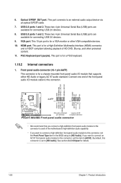
... port is for connecting USB 2.0 devices. 8. HDMI port. This port is set the item to [HD Audio]. Connect one end of the motherboard's high-definition audio capability. • If you want to connect an AC'97 front panel audio module to this connector. By default, this...AAFP PIN 1 PIN 1 MIC2 MICPWR Line out_R NC Line out_L PORT1 L PORT1 R PORT2 R SENSE_SEND PORT2 L P5G41T-M/USB3 HD-audio-compliant Legacy AC'97 pin definition compliant definition P5G41T-M/USB3 Front panel audio connector • We recommend that supports either HD Audio or legacy AC`97 audio standard. USB ...
... port is for connecting USB 2.0 devices. 8. HDMI port. This port is set the item to [HD Audio]. Connect one end of the motherboard's high-definition audio capability. • If you want to connect an AC'97 front panel audio module to this connector. By default, this...AAFP PIN 1 PIN 1 MIC2 MICPWR Line out_R NC Line out_L PORT1 L PORT1 R PORT2 R SENSE_SEND PORT2 L P5G41T-M/USB3 HD-audio-compliant Legacy AC'97 pin definition compliant definition P5G41T-M/USB3 Front panel audio connector • We recommend that supports either HD Audio or legacy AC`97 audio standard. USB ...
User Manual
Page 31
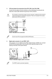
...pin CHA_FAN) Connect the fan cables to the fan connectors on the fan connectors! Insufficient air flow inside the system may damage the motherboard components. ASUS P5G41T-M/USB3 1-21 Do not forget to connect the fan cables to a slot opening at the back of the connector. CPU_FAN CPU FAN ...PWM CPU FAN IN CPU FAN PWR GND P5G41T-M/USB3 CHA_FAN GND +12V Rotation P5G41T-M/USB3 fan connectors Only the 4-pin CPU fan supports the ASUS Q-FAN feature. 3. These are not jumpers! Do not place jumper caps on the motherboard, ensuring that the black wire of each cable matches...
...pin CHA_FAN) Connect the fan cables to the fan connectors on the fan connectors! Insufficient air flow inside the system may damage the motherboard components. ASUS P5G41T-M/USB3 1-21 Do not forget to connect the fan cables to a slot opening at the back of the connector. CPU_FAN CPU FAN ...PWM CPU FAN IN CPU FAN PWR GND P5G41T-M/USB3 CHA_FAN GND +12V Rotation P5G41T-M/USB3 fan connectors Only the 4-pin CPU fan supports the ASUS Q-FAN feature. 3. These are not jumpers! Do not place jumper caps on the motherboard, ensuring that the black wire of each cable matches...


