User Manual
Page 1
Motherboard P5G41T-M LX2 Series • P5G41T-M LX2 • P5G41T-M LX2/GB • P5G41T-M LX2/GB/LPT
Motherboard P5G41T-M LX2 Series • P5G41T-M LX2 • P5G41T-M LX2/GB • P5G41T-M LX2/GB/LPT
User Manual
Page 3
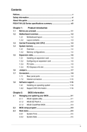
Contents Notices...v Safety information vi About this guide vi P5G41T-M LX2 Series specifications summary viii Chapter 1: Product introduction 1.1 Before you proceed 1-1 1.2 Motherboard overview 1-2 1.2.1 Motherboard layout 1-2 1.2.2 Layout contents 1-3 1.3 Central Processing ...operating system 1-16 1.8.2 Support DVD information 1-16 Chapter 2: BIOS information 2.1 Managing and updating your BIOS 2-1 2.1.1 ASUS Update utility 2-1 2.1.2 ASUS EZ Flash 2 2-2 2.1.3 ASUS CrashFree BIOS 2-3 2.2 BIOS setup program 2-3 2.3 Main menu 2-4 2.3.1 System Time 2-4 2.3.2 System Date 2-4 iii
Contents Notices...v Safety information vi About this guide vi P5G41T-M LX2 Series specifications summary viii Chapter 1: Product introduction 1.1 Before you proceed 1-1 1.2 Motherboard overview 1-2 1.2.1 Motherboard layout 1-2 1.2.2 Layout contents 1-3 1.3 Central Processing ...operating system 1-16 1.8.2 Support DVD information 1-16 Chapter 2: BIOS information 2.1 Managing and updating your BIOS 2-1 2.1.1 ASUS Update utility 2-1 2.1.2 ASUS EZ Flash 2 2-2 2.1.3 ASUS CrashFree BIOS 2-3 2.2 BIOS setup program 2-3 2.3 Main menu 2-4 2.3.1 System Time 2-4 2.3.2 System Date 2-4 iii
User Manual
Page 8
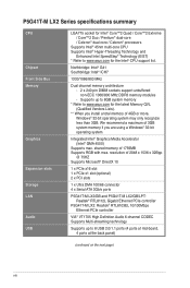
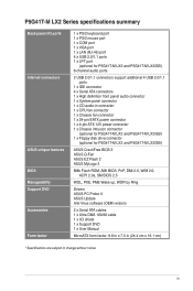
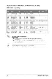
... 1 x Ultra DMA 100/66 connector 4 x Serial ATA 3Gb/s ports P5G41T-M LX2/GB and P5G41T-M LX2/GB/LPT: Realtek® RTL8112L Gigabit Ethernet PCIe controller P5G41T-M LX2: Realtek® RTL8103EL 10/100Mbps Ethernet PCIe controller VIA® VT1705 High ...Definition Audio 6-channel CODEC Supports Multi-streaming technology Supports up to 8GB system memory * Refer to 8 USB 2.0/1.1 ports (4 ports at mid-board, 4 ports at the back panel) (continued on the next page) viii Supports up to www.asus...
... 1 x Ultra DMA 100/66 connector 4 x Serial ATA 3Gb/s ports P5G41T-M LX2/GB and P5G41T-M LX2/GB/LPT: Realtek® RTL8112L Gigabit Ethernet PCIe controller P5G41T-M LX2: Realtek® RTL8103EL 10/100Mbps Ethernet PCIe controller VIA® VT1705 High ...Definition Audio 6-channel CODEC Supports Multi-streaming technology Supports up to 8GB system memory * Refer to 8 USB 2.0/1.1 ports (4 ports at mid-board, 4 ports at the back panel) (continued on the next page) viii Supports up to www.asus...
User Manual
Page 9
... fan connector 1 x 24-pin EATX power connector 1 x 4-pin ATX 12V power connector 1 x Chassis intrusion connector (optional for P5G41T-M LX2 and P5G41T-M LX2/GB) 1 x Floppy disk drive connector (optional for P5G41T-M LX2 and P5G41T-M LX2/GB) ASUS CrashFree BIOS 3 ASUS Q-Fan ASUS EZ Flash 2 ASUS MyLogo 2 8Mb Flash ROM, AMI BIOS, PnP, DMI 2.0, WfM 2.0, ACPI 2.0a, SM BIOS 2.5 WOL, PXE, PME Wake up...
... fan connector 1 x 24-pin EATX power connector 1 x 4-pin ATX 12V power connector 1 x Chassis intrusion connector (optional for P5G41T-M LX2 and P5G41T-M LX2/GB) 1 x Floppy disk drive connector (optional for P5G41T-M LX2 and P5G41T-M LX2/GB) ASUS CrashFree BIOS 3 ASUS Q-Fan ASUS EZ Flash 2 ASUS MyLogo 2 8Mb Flash ROM, AMI BIOS, PnP, DMI 2.0, WfM 2.0, ACPI 2.0a, SM BIOS 2.5 WOL, PXE, PME Wake up...
User Manual
Page 10
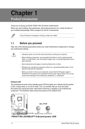
... is a reminder that you for the list of accessories. Refer to page ix for buying an ASUS® P5G41T-M LX2 Series motherboard! SB_PWR P5G41T-M LX2/GB/LPT ON OFF Standby Power Powered Off P5G41T-M LX2/GB/LPT Onboard power LED 1-1 ASUS P5G41T-M LX2 Series Chapter 1 Product introduction Thank you must shut down the system and unplug the power cable before...
... is a reminder that you for the list of accessories. Refer to page ix for buying an ASUS® P5G41T-M LX2 Series motherboard! SB_PWR P5G41T-M LX2/GB/LPT ON OFF Standby Power Powered Off P5G41T-M LX2/GB/LPT Onboard power LED 1-1 ASUS P5G41T-M LX2 Series Chapter 1 Product introduction Thank you must shut down the system and unplug the power cable before...
User Manual
Page 11
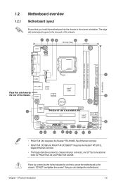
... RTL 8112L ICS 9LPRS441 Intel® G41 Lithium Cell CMOS Power PRI_IDE 7 2 24.4cm(9.6in) EATXPWR Super PCIEX16 I/O 17 P5G41T-M LX2/GB/LPT SATA4 SATA3 8Mb PCI1 Intel® SATA2 BIOS SATA1 ICH7 PCI2 8 VIA VT1705 CD FLOPPY SB_PWR USBPW5-8 USB56 USB78 CLRTC... AAFP CHASSIS F_PANEL 16 15 14 4 13 12 11 10 9 • P5G41T-M LX2 integrates the Realtek® RTL8103EL Fast Ethernet controller. • P5G41T-M LX2/GB and P5G41T-M LX2/GB/LPT integrate the Realtek® RTL8112L Gigabit Ethernet controller. • The floppy disk drive connector...
... RTL 8112L ICS 9LPRS441 Intel® G41 Lithium Cell CMOS Power PRI_IDE 7 2 24.4cm(9.6in) EATXPWR Super PCIEX16 I/O 17 P5G41T-M LX2/GB/LPT SATA4 SATA3 8Mb PCI1 Intel® SATA2 BIOS SATA1 ICH7 PCI2 8 VIA VT1705 CD FLOPPY SB_PWR USBPW5-8 USB56 USB78 CLRTC... AAFP CHASSIS F_PANEL 16 15 14 4 13 12 11 10 9 • P5G41T-M LX2 integrates the Realtek® RTL8103EL Fast Ethernet controller. • P5G41T-M LX2/GB and P5G41T-M LX2/GB/LPT integrate the Realtek® RTL8112L Gigabit Ethernet controller. • The floppy disk drive connector...
User Manual
Page 12
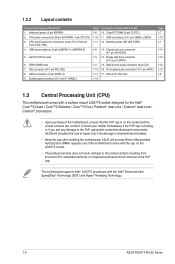
...LED (SB_PWR) 1-8 13. Chassis intrusion connector (4-1 pin CHASSIS) 1-3 14. Front panel audio connector (10-1 pin AAFP) 1-11 17. ASUS will shoulder the cost of repair only if the damage is on the LGA775 socket. • The product warranty does not cover damage to...Processing Unit (CPU) This motherboard comes with the Intel® Enhanced Intel SpeedStep® Technology (EIST) and Hyper-Threading Technology. 1-3 ASUS P5G41T-M LX2 Series ASUS will process Return Merchandise Authorization (RMA) requests only if the motherboard comes with the cap on the socket and the socket contacts are ...
...LED (SB_PWR) 1-8 13. Chassis intrusion connector (4-1 pin CHASSIS) 1-3 14. Front panel audio connector (10-1 pin AAFP) 1-11 17. ASUS will shoulder the cost of repair only if the damage is on the LGA775 socket. • The product warranty does not cover damage to...Processing Unit (CPU) This motherboard comes with the Intel® Enhanced Intel SpeedStep® Technology (EIST) and Hyper-Threading Technology. 1-3 ASUS P5G41T-M LX2 Series ASUS will process Return Merchandise Authorization (RMA) requests only if the motherboard comes with the cap on the socket and the socket contacts are ...

User Manual
Page 13
... for the dual-channel configuration. The system maps the total size of the DDR3 DIMM sockets: DIMM_A1 DIMM_B1 Channel Channel A Channel B Sockets DIMM_A1 DIMM_B1 P5G41T-M LX2/GB/LPT P5G41T-M LX2/GB/LPT 240-pin DDR3 DIMM sockets 1.4.2 Memory configurations You may install 512MB, 1GB, 2GB, and 4GB unbuffered non‑ECC DDR3 DIMMs into...
... for the dual-channel configuration. The system maps the total size of the DDR3 DIMM sockets: DIMM_A1 DIMM_B1 Channel Channel A Channel B Sockets DIMM_A1 DIMM_B1 P5G41T-M LX2/GB/LPT P5G41T-M LX2/GB/LPT 240-pin DDR3 DIMM sockets 1.4.2 Memory configurations You may install 512MB, 1GB, 2GB, and 4GB unbuffered non‑ECC DDR3 DIMMs into...
User Manual
Page 14
P5G41T-M LX2 Series Motherboard Qualified Vendors Lists (QVL) DDR3-1066MHz capability Vendor Part No. Timing Dimm (Bios) Voltage Crucial CT12864BA1067.8FF 1024MB SS Crucial CT25664BA1067.16FF 2048MB ... one pair of modules inserted into both slots as one pair of dual-channel memory configuration. Size SS/ Chip DS Brand Chip NO. Visit the ASUS website at www.asus.com for the latest QVL. 1-5 ASUS P5G41T-M LX2 Series
P5G41T-M LX2 Series Motherboard Qualified Vendors Lists (QVL) DDR3-1066MHz capability Vendor Part No. Timing Dimm (Bios) Voltage Crucial CT12864BA1067.8FF 1024MB SS Crucial CT25664BA1067.16FF 2048MB ... one pair of modules inserted into both slots as one pair of dual-channel memory configuration. Size SS/ Chip DS Brand Chip NO. Visit the ASUS website at www.asus.com for the latest QVL. 1-5 ASUS P5G41T-M LX2 Series
User Manual
Page 16
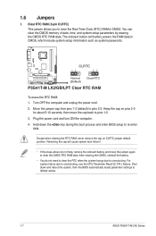
... the RAM data in CMOS. Move the jumper cap from pins 1-2 (default) to default values. 1-7 ASUS P5G41T-M LX2 Series Plug the power cord and turn ON the computer. 4. CLRTC 12 23 P5G41T-M LX2/GB/LPT Normal (Default) Clear RTC P5G41T-M LX2/GB/LPT Clear RTC RAM To erase the RTC RAM: 1. Shut down the key during the...
... the RAM data in CMOS. Move the jumper cap from pins 1-2 (default) to default values. 1-7 ASUS P5G41T-M LX2 Series Plug the power cord and turn ON the computer. 4. CLRTC 12 23 P5G41T-M LX2/GB/LPT Normal (Default) Clear RTC P5G41T-M LX2/GB/LPT Clear RTC RAM To erase the RTC RAM: 1. Shut down the key during the...
User Manual
Page 17
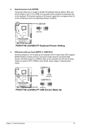
... wake-up the computer from S1 sleep mode (CPU stopped, DRAM refreshed, system running in reduced power mode). KBPWR 12 23 +5V +5VSB (Default) P5G41T-M LX2/GB/LPT P5G41T-M LX2/GB/LPT Keyboard Power Setting 3. Set these jumpers to +5VSB to wake up the computer from S3 and S4 sleep modes (no power to... +5V to CPU, DRAM in slow refresh, power supply in low power mode) using the connected USB devices. USBPW1-4 12 23 +5V +5VSB (Default) USBPW5-8 P5G41T-M LX2/GB/LPT 12 23 +5V +5VSB (Default) P5G41T-M LX2/GB/LPT USB Device Wake Up Chapter 1: Product introduction 1-8
... wake-up the computer from S1 sleep mode (CPU stopped, DRAM refreshed, system running in reduced power mode). KBPWR 12 23 +5V +5VSB (Default) P5G41T-M LX2/GB/LPT P5G41T-M LX2/GB/LPT Keyboard Power Setting 3. Set these jumpers to +5VSB to wake up the computer from S3 and S4 sleep modes (no power to... +5V to CPU, DRAM in slow refresh, power supply in low power mode) using the connected USB devices. USBPW1-4 12 23 +5V +5VSB (Default) USBPW5-8 P5G41T-M LX2/GB/LPT 12 23 +5V +5VSB (Default) P5G41T-M LX2/GB/LPT USB Device Wake Up Chapter 1: Product introduction 1-8
User Manual
Page 18
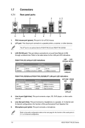
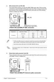
In 4-channel and 6-channel configurations, the function of the audio ports in 2, 4, or 6-channel configuration. 1-9 ASUS P5G41T-M LX2 Series This port allows connection to the table below for the function of this port becomes Front Speaker Out. 6. This port ...port connects to the audio configuration table on the next page for the LAN port LED indications. The LPT port is for P5G41T-M LX2 and P5G41T-M LX2/GB. 3. P5G41T-M LX2 LAN port LED indications LED (Orange) Status OFF ORANGE Description No link 100Mbps connection LED (Green) Status OFF GREEN Description...
In 4-channel and 6-channel configurations, the function of the audio ports in 2, 4, or 6-channel configuration. 1-9 ASUS P5G41T-M LX2 Series This port allows connection to the table below for the function of this port becomes Front Speaker Out. 6. This port ...port connects to the audio configuration table on the next page for the LAN port LED indications. The LPT port is for P5G41T-M LX2 and P5G41T-M LX2/GB. 3. P5G41T-M LX2 LAN port LED indications LED (Orange) Status OFF ORANGE Description No link 100Mbps connection LED (Green) Status OFF GREEN Description...

User Manual
Page 19
... +5 Volts +12 Volts +5 Volts +5V Standby +5 Volts Power OK -5 Volts PIN 1 GND +5 Volts GND GND GND GND GND GND P5G41T-M LX2/GB/LPT +5 Volts GND PSON# GND +3 Volts -12 Volts +3 Volts +3 Volts PIN 1 P5G41T-M LX2/GB/LPT ATX power connectors • For a fully configured system, we recommend that you use a PSU with a higher power... more power-consuming devices or when you use a power supply unit (PSU) that you intend to the Recommended Power Supply Wattage Calculator at http://support.asus. Chapter 1: Product introduction 1-10
... +5 Volts +12 Volts +5 Volts +5V Standby +5 Volts Power OK -5 Volts PIN 1 GND +5 Volts GND GND GND GND GND GND P5G41T-M LX2/GB/LPT +5 Volts GND PSON# GND +3 Volts -12 Volts +3 Volts +3 Volts PIN 1 P5G41T-M LX2/GB/LPT ATX power connectors • For a fully configured system, we recommend that you use a PSU with a higher power... more power-consuming devices or when you use a power supply unit (PSU) that you intend to the Recommended Power Supply Wattage Calculator at http://support.asus. Chapter 1: Product introduction 1-10
User Manual
Page 20
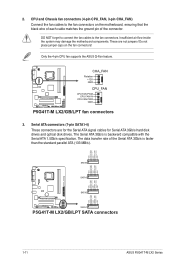
... CHA_FAN Rotation +12V GND CPU_FAN CPU FAN PWM CPU FAN IN CPU FAN PWR GND P5G41T-M LX2/GB/LPT fan connectors 3. The data transfer rate of the connector. CPU and Chassis fan connectors (4-pin CPU_FAN, 3-pin CHA_FAN) Connect the ...RSATA_RXP3 GND RSATA_TXN3 RSATA_TXP3 GND SATA3 GND RSATA_RXN2 RSATA_RXP2 GND RSATA_TXN2 RSATA_TXP2 GND GND RSATA_RXN1 RSATA_RXP1 GND RSATA_TXN1 RSATA_TXP1 GND P5G41T-M LX2/GB/LPT SATA2 SATA1 P5G41T-M LX2/GB/LPT SATA connectors 1-11 ASUS P5G41T-M LX2 Series These are for the Serial ATA signal cables for Serial ATA 3Gb/s hard disk drives and optical disk...
... CHA_FAN Rotation +12V GND CPU_FAN CPU FAN PWM CPU FAN IN CPU FAN PWR GND P5G41T-M LX2/GB/LPT fan connectors 3. The data transfer rate of the connector. CPU and Chassis fan connectors (4-pin CPU_FAN, 3-pin CHA_FAN) Connect the ...RSATA_RXP3 GND RSATA_TXN3 RSATA_TXP3 GND SATA3 GND RSATA_RXN2 RSATA_RXP2 GND RSATA_TXN2 RSATA_TXP2 GND GND RSATA_RXN1 RSATA_RXP1 GND RSATA_TXN1 RSATA_TXP1 GND P5G41T-M LX2/GB/LPT SATA2 SATA1 P5G41T-M LX2/GB/LPT SATA connectors 1-11 ASUS P5G41T-M LX2 Series These are for the Serial ATA signal cables for Serial ATA 3Gb/s hard disk drives and optical disk...
User Manual
Page 21
...receive stereo audio input from sound sources such as "Cable-Select," ensure that all other device jumpers have the same setting. 5. PIN1 PRI_IDE P5G41T-M LX2/GB/LPT NOTE:Orient the red markings on each Ultra DMA 100/66 signal cable: blue, black, and gray. CD Right Audio Channel... GND GND Left Audio Channel P5G41T-M LX2/GB/LPT P5G41T-M LX2/GB/LPT Internal audio connector Chapter 1: Product introduction 1-12 Connect the blue connector to the motherboard's IDE connector, then select one of...
...receive stereo audio input from sound sources such as "Cable-Select," ensure that all other device jumpers have the same setting. 5. PIN1 PRI_IDE P5G41T-M LX2/GB/LPT NOTE:Orient the red markings on each Ultra DMA 100/66 signal cable: blue, black, and gray. CD Right Audio Channel... GND GND Left Audio Channel P5G41T-M LX2/GB/LPT P5G41T-M LX2/GB/LPT Internal audio connector Chapter 1: Product introduction 1-12 Connect the blue connector to the motherboard's IDE connector, then select one of...
User Manual
Page 22
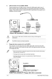
...connector at the back of the floppy disk drive. • Pin 5 on the floppy ribbon cable to PIN 1. P5G41T-M LX2/GB/LPT Floppy disk drive connector 1-13 ASUS P5G41T-M LX2 Series The USB 2.0 module is for the floppy disk drive (FDD) signal cable. These USB connectors comply with a ...red markings on the connector is an optional item for USB 2.0 ports. USB connectors (10-1 pin USB56, USB78) These connectors are for P5G41T-M LX2 and P5G41T-M LX2/GB. Floppy disk drive connector (34-1 pin FLOPPY) This connector is purchased separately. 7. 6. Connect the USB module cable to any ...
...connector at the back of the floppy disk drive. • Pin 5 on the floppy ribbon cable to PIN 1. P5G41T-M LX2/GB/LPT Floppy disk drive connector 1-13 ASUS P5G41T-M LX2 Series The USB 2.0 module is for the floppy disk drive (FDD) signal cable. These USB connectors comply with a ...red markings on the connector is an optional item for USB 2.0 ports. USB connectors (10-1 pin USB56, USB78) These connectors are for P5G41T-M LX2 and P5G41T-M LX2/GB. Floppy disk drive connector (34-1 pin FLOPPY) This connector is purchased separately. 7. 6. Connect the USB module cable to any ...
User Manual
Page 23
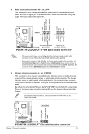
... PIN 1 MIC2 MICPWR Line out_R NC Line out_L PORT1 L PORT1 R PORT2 R SENSE_SEND PORT2 L P5G41T-M LX2/GB/LPT HD-audio-compliant Legacy AC'97 pin definition compliant definition P5G41T-M LX2/GB/LPT Front panel audio connector • We recommend that supports either HD Audio or legacy AC...audio standard. The Chassis intrusion connector is set the item to use the chassis intrusion detection feature. See section 2.4.2 Chipset for P5G41T-M LX2 and P5G41T-M LX2/GB. The chassis intrusion sensor or switch sends a high-level signal to this connector to avail of the motherboard's high-...
... PIN 1 MIC2 MICPWR Line out_R NC Line out_L PORT1 L PORT1 R PORT2 R SENSE_SEND PORT2 L P5G41T-M LX2/GB/LPT HD-audio-compliant Legacy AC'97 pin definition compliant definition P5G41T-M LX2/GB/LPT Front panel audio connector • We recommend that supports either HD Audio or legacy AC...audio standard. The Chassis intrusion connector is set the item to use the chassis intrusion detection feature. See section 2.4.2 Chipset for P5G41T-M LX2 and P5G41T-M LX2/GB. The chassis intrusion sensor or switch sends a high-level signal to this connector to avail of the motherboard's high-...
User Manual
Page 24
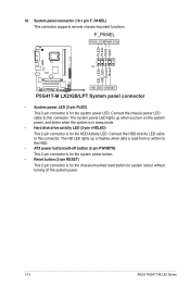
...HDD Activity LED. Ground Reset 10. Connect the chassis power LED cable to this connector. F_PANEL PWR LED PWR BTN PIN 1 P5G41T-M LX2/GB/LPT HD LED RESET P5G41T-M LX2/GB/LPT System panel connector • System power LED (2-pin PLED) This 2-pin connector is for the chassis-mounted reset ... power button. • Reset button (2-pin RESET) This 2-pin connector is for system reboot without turning off the system power. 1-15 ASUS P5G41T-M LX2 Series System panel connector (10-1 pin F_PANEL) This connector supports several chassis-mounted functions. PLED+ PLEDPWR GND IDE_LED+ IDE_LED-
...HDD Activity LED. Ground Reset 10. Connect the chassis power LED cable to this connector. F_PANEL PWR LED PWR BTN PIN 1 P5G41T-M LX2/GB/LPT HD LED RESET P5G41T-M LX2/GB/LPT System panel connector • System power LED (2-pin PLED) This 2-pin connector is for the chassis-mounted reset ... power button. • Reset button (2-pin RESET) This 2-pin connector is for system reboot without turning off the system power. 1-15 ASUS P5G41T-M LX2 Series System panel connector (10-1 pin F_PANEL) This connector supports several chassis-mounted functions. PLED+ PLEDPWR GND IDE_LED+ IDE_LED-
User Manual
Page 26
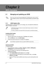
... update the BIOS using the ASUS Update utility. 2.1.1 ASUS Update utility The ASUS Update is a utility that comes with the motherboard package. Click the Utilities tab, then click ASUS Update. 3. Select the ASUS FTP site nearest you to download then click Next. 2-1 ASUS P5G41T-M LX2 Series The Drivers menu appears....USB flash disk in case you want to manage, save, and update the motherboard BIOS in Windows® environment. • ASUS Update requires an Internet connection either through a network or an Internet Service Provider (ISP). • This utility is available in the ...
... update the BIOS using the ASUS Update utility. 2.1.1 ASUS Update utility The ASUS Update is a utility that comes with the motherboard package. Click the Utilities tab, then click ASUS Update. 3. Select the ASUS FTP site nearest you to download then click Next. 2-1 ASUS P5G41T-M LX2 Series The Drivers menu appears....USB flash disk in case you want to manage, save, and update the motherboard BIOS in Windows® environment. • ASUS Update requires an Internet connection either through a network or an Internet Service Provider (ISP). • This utility is available in the ...
User Manual
Page 27
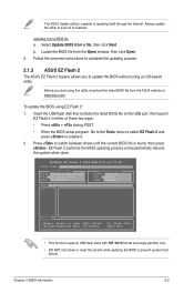
... 2 in either of updating itself through the Internet. EZ Flash 2 performs the BIOS updating process and automatically reboots the system when done. The ASUS Update utility is found, then press . Updating from the Open window, then click Open. 3. ASUSTek EZ Flash 2 BIOS ROM Utility V3.44... FLASH TYPE: MXIC 25L8005 Current ROM BOARD:P5G41T-M LX2/GB/LPT VER:0305 (H:00 B:00) DATE: 10/29/2009 Update ROM BOARD: Unknown VER: Unknown DATE: Unknown PATH: A:\ A: Note [Enter] Select...
... 2 in either of updating itself through the Internet. EZ Flash 2 performs the BIOS updating process and automatically reboots the system when done. The ASUS Update utility is found, then press . Updating from the Open window, then click Open. 3. ASUSTek EZ Flash 2 BIOS ROM Utility V3.44... FLASH TYPE: MXIC 25L8005 Current ROM BOARD:P5G41T-M LX2/GB/LPT VER:0305 (H:00 B:00) DATE: 10/29/2009 Update ROM BOARD: Unknown VER: Unknown DATE: Unknown PATH: A:\ A: Note [Enter] Select...
