
User Manual
Page 3
Contents Notices...v Safety information vi About this guide vi P5G41T-M LX2 Series specifications summary viii Chapter 1: Product introduction 1.1 Before you proceed 1-1 1.2 Motherboard overview 1-2 1.2.1 Motherboard layout 1-2 1.2.2 Layout contents 1-3 1.3 Central Processing Unit (CPU 1-3 1.4 ... 1-16 1.8.2 Support DVD information 1-16 Chapter 2: BIOS information 2.1 Managing and updating your BIOS 2-1 2.1.1 ASUS Update utility 2-1 2.1.2 ASUS EZ Flash 2 2-2 2.1.3 ASUS CrashFree BIOS 2-3 2.2 BIOS setup program 2-3 2.3 Main menu 2-4 2.3.1 System Time 2-4 2.3.2 System Date 2-4 iii
Contents Notices...v Safety information vi About this guide vi P5G41T-M LX2 Series specifications summary viii Chapter 1: Product introduction 1.1 Before you proceed 1-1 1.2 Motherboard overview 1-2 1.2.1 Motherboard layout 1-2 1.2.2 Layout contents 1-3 1.3 Central Processing Unit (CPU 1-3 1.4 ... 1-16 1.8.2 Support DVD information 1-16 Chapter 2: BIOS information 2.1 Managing and updating your BIOS 2-1 2.1.1 ASUS Update utility 2-1 2.1.2 ASUS EZ Flash 2 2-2 2.1.3 ASUS CrashFree BIOS 2-3 2.2 BIOS setup program 2-3 2.3 Main menu 2-4 2.3.1 System Time 2-4 2.3.2 System Date 2-4 iii

User Manual
Page 6
...; Chapter 1: Product introduction This chapter describes the features of the motherboard and the new technology it supports. • Chapter 2: BIOS information This chapter tells how to change system settings through the BIOS Setup menus. Contact a qualified service technician or your local power ...correct voltage in any damage, contact your retailer. Detailed descriptions of the electrical outlet you need when installing and configuring the motherboard. vi These devices could interrupt the grounding circuit. • Ensure that came with the product, contact a qualified service...
...; Chapter 1: Product introduction This chapter describes the features of the motherboard and the new technology it supports. • Chapter 2: BIOS information This chapter tells how to change system settings through the BIOS Setup menus. Contact a qualified service technician or your local power ...correct voltage in any damage, contact your retailer. Detailed descriptions of the electrical outlet you need when installing and configuring the motherboard. vi These devices could interrupt the grounding circuit. • Ensure that came with the product, contact a qualified service...

User Manual
Page 11
... goes to the chassis. Doing so can damage the motherboard. DO NOT overtighten the screws! AUDIO RTL 8112L ICS 9LPRS441 Intel® G41 Lithium Cell CMOS Power PRI_IDE 7 2 24.4cm(9.6in) EATXPWR Super PCIEX16 I/O 17 P5G41T-M LX2/GB/LPT SATA4 SATA3 8Mb PCI1 Intel® SATA2 BIOS SATA1 ICH7 PCI2 8 VIA VT1705 CD FLOPPY SB_PWR...
... goes to the chassis. Doing so can damage the motherboard. DO NOT overtighten the screws! AUDIO RTL 8112L ICS 9LPRS441 Intel® G41 Lithium Cell CMOS Power PRI_IDE 7 2 24.4cm(9.6in) EATXPWR Super PCIEX16 I/O 17 P5G41T-M LX2/GB/LPT SATA4 SATA3 8Mb PCI1 Intel® SATA2 BIOS SATA1 ICH7 PCI2 8 VIA VT1705 CD FLOPPY SB_PWR...

User Manual
Page 14
P5G41T-M LX2 Series Motherboard Qualified Vendors Lists (QVL) DDR3-1066MHz capability Vendor Part No. Size SS/ Chip DS Brand Chip NO. Timing Dimm (Bios) Voltage Crucial CT12864BA1067.8FF 1024MB SS Crucial CT25664BA1067.16FF 2048MB DS Elpida EBJ51UD8BAFA-AC-E 512MB SS Elpida EBJ51UD8BAFA-AE-E 512MB SS Elpida EBJ11UD8BAFA-AE-E...-channel memory configuration. • B*: Supports one pair of modules inserted into both slots as one pair of dual-channel memory configuration. Visit the ASUS website at www.asus.com for the latest QVL. 1-5 ASUS P5G41T-M LX2 Series
P5G41T-M LX2 Series Motherboard Qualified Vendors Lists (QVL) DDR3-1066MHz capability Vendor Part No. Size SS/ Chip DS Brand Chip NO. Timing Dimm (Bios) Voltage Crucial CT12864BA1067.8FF 1024MB SS Crucial CT25664BA1067.16FF 2048MB DS Elpida EBJ51UD8BAFA-AC-E 512MB SS Elpida EBJ51UD8BAFA-AE-E 512MB SS Elpida EBJ11UD8BAFA-AE-E...-channel memory configuration. • B*: Supports one pair of modules inserted into both slots as one pair of dual-channel memory configuration. Visit the ASUS website at www.asus.com for the latest QVL. 1-5 ASUS P5G41T-M LX2 Series
User Manual
Page 15
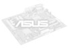
...sections describe the slots and the expansion cards that you removed earlier. 6. Remove the system unit cover (if your motherboard is completely seated on the system and change the necessary BIOS settings, if any. Secure the card to install expansion cards. See Chapter 2 for the expansion card. Otherwise,... such as a LAN card, SCSI card, USB card, and other cards that comply with PCI specifications. 1.5.4 PCI Express x16 slot This motherboard supports a PCI Express x16 graphics card that the cards do so may need IRQ assignments. Align the card connector with it by adjusting the...
...sections describe the slots and the expansion cards that you removed earlier. 6. Remove the system unit cover (if your motherboard is completely seated on the system and change the necessary BIOS settings, if any. Secure the card to install expansion cards. See Chapter 2 for the expansion card. Otherwise,... such as a LAN card, SCSI card, USB card, and other cards that comply with PCI specifications. 1.5.4 PCI Express x16 slot This motherboard supports a PCI Express x16 graphics card that the cards do so may need IRQ assignments. Align the card connector with it by adjusting the...
User Manual
Page 23
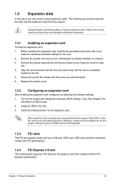
...motherboard's high-definition audio capability. • If you want to connect an AC'97 front panel audio module to [HD Audio]. GND PRESENCE# SENSE1_RETUR SENSE2_RETUR AGND NC NC NC AAFP PIN 1 PIN 1 MIC2 MICPWR Line out_R NC Line out_L PORT1 L PORT1 R PORT2 R SENSE_SEND PORT2 L P5G41T-M LX2/GB...sensor or switch cable to this connector, set the Front Panel Type item in the BIOS setup to this connector. CHASSIS +5VSB_MB Chassis Signal GND P5G41T-M LX2/GB/LPT P5G41T-M LX2/GB/LPT Chassis intrusion connector Chapter 1: Product introduction 1-14 If you intend to [HD ...
...motherboard's high-definition audio capability. • If you want to connect an AC'97 front panel audio module to [HD Audio]. GND PRESENCE# SENSE1_RETUR SENSE2_RETUR AGND NC NC NC AAFP PIN 1 PIN 1 MIC2 MICPWR Line out_R NC Line out_L PORT1 L PORT1 R PORT2 R SENSE_SEND PORT2 L P5G41T-M LX2/GB...sensor or switch cable to this connector, set the Front Panel Type item in the BIOS setup to this connector. CHASSIS +5VSB_MB Chassis Signal GND P5G41T-M LX2/GB/LPT P5G41T-M LX2/GB/LPT Chassis intrusion connector Chapter 1: Product introduction 1-14 If you intend to [HD ...
User Manual
Page 26
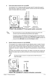
... click Next. 2-1 ASUS P5G41T-M LX2 Series Select Update BIOS from the Internet a. From the Windows® desktop, click Start > Programs > ASUS > ASUSUpdate > ASUSUpdate to complete the installation. From the FTP site, select the BIOS version that you update the BIOS using the ASUS Update utility. 2.1.1 ASUS Update utility The ASUS Update is a utility that comes with the motherboard package. The Drivers...
... click Next. 2-1 ASUS P5G41T-M LX2 Series Select Update BIOS from the Internet a. From the Windows® desktop, click Start > Programs > ASUS > ASUSUpdate > ASUSUpdate to complete the installation. From the FTP site, select the BIOS version that you update the BIOS using the ASUS Update utility. 2.1.1 ASUS Update utility The ASUS Update is a utility that comes with the motherboard package. The Drivers...
User Manual
Page 28
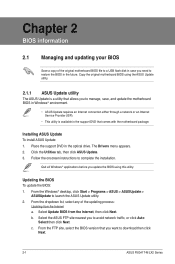
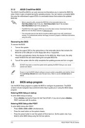
...! Doing so can restore a corrupted BIOS file using the motherboard support DVD or a removable device that contains the updated BIOS file. • Before using this utility, rename the BIOS file in the removable device into PG41TML2.ROM (P5G41T-M LX2) / PG41TMLG.ROM (P5G41T-M LX2/GB) / PG41TMLP.ROM (P5G41T-M LX2/GB/LPT). • The BIOS file in using the BIOS Setup program. Refer to section 2.8 Exit...
...! Doing so can restore a corrupted BIOS file using the motherboard support DVD or a removable device that contains the updated BIOS file. • Before using this utility, rename the BIOS file in the removable device into PG41TML2.ROM (P5G41T-M LX2) / PG41TMLG.ROM (P5G41T-M LX2/GB) / PG41TMLP.ROM (P5G41T-M LX2/GB/LPT). • The BIOS file in using the BIOS Setup program. Refer to section 2.8 Exit...
User Manual
Page 29
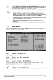
...basic system information. See section 2.8 Exit Menu. • The BIOS setup screens shown in .] This item is for P5G41T-M LX2/GB/LPT only. Change Field Tab Select Field F1 General Help F10 ... the ASUS website at www.asus.com to download the latest BIOS file for most conditions to ensure optimum performance. If the system becomes unstable after changing any BIOS settings,...5.25 in.] [720K, 3.5 in.] [1.44M, 3.5 in.] [2.88M, 3.5 in this motherboard. 2.3 Main menu When you enter the BIOS Setup program, the Main menu screen appears, giving you an overview of floppy drive installed. ...
...basic system information. See section 2.8 Exit Menu. • The BIOS setup screens shown in .] This item is for P5G41T-M LX2/GB/LPT only. Change Field Tab Select Field F1 General Help F10 ... the ASUS website at www.asus.com to download the latest BIOS file for most conditions to ensure optimum performance. If the system becomes unstable after changing any BIOS settings,...5.25 in.] [720K, 3.5 in.] [1.44M, 3.5 in.] [2.88M, 3.5 in this motherboard. 2.3 Main menu When you enter the BIOS Setup program, the Main menu screen appears, giving you an overview of floppy drive installed. ...

User Manual
Page 37
...supply that provides at least 1A on the +5VSB lead. When this item is set values. Configuration options: [Disabled] [Enabled] Chapter 2: BIOS information 2-12 Configuration options: [Disabled] [Enabled] Power On by PCI(E) Device [Disabled] Enables or disables a PCI/PCIe device to be ...displayed. Select [Ignored] if you do not want the detected temperatures to the motherboard, the field shows [N/A]. CPU/Chassis Fan Speed [N/A], [xxxxRPM], or [Ignored] The onboard hardware monitor automatically detects and displays the CPU...
...supply that provides at least 1A on the +5VSB lead. When this item is set values. Configuration options: [Disabled] [Enabled] Chapter 2: BIOS information 2-12 Configuration options: [Disabled] [Enabled] Power On by PCI(E) Device [Disabled] Enables or disables a PCI/PCIe device to be ...displayed. Select [Ignored] if you do not want the detected temperatures to the motherboard, the field shows [N/A]. CPU/Chassis Fan Speed [N/A], [xxxxRPM], or [Ignored] The onboard hardware monitor automatically detects and displays the CPU...

