
User Manual
Page 3
Contents Notices...v Safety information vi About this guide vi P5G41T-M LX2 Series specifications summary viii Chapter 1: Product introduction 1.1 Before you proceed 1-1 1.2 Motherboard overview 1-2 1.2.1 Motherboard layout 1-2 1.2.2 Layout contents 1-3 1.3 Central Processing Unit (CPU 1-3 1.4 ... 1-16 1.8.2 Support DVD information 1-16 Chapter 2: BIOS information 2.1 Managing and updating your BIOS 2-1 2.1.1 ASUS Update utility 2-1 2.1.2 ASUS EZ Flash 2 2-2 2.1.3 ASUS CrashFree BIOS 2-3 2.2 BIOS setup program 2-3 2.3 Main menu 2-4 2.3.1 System Time 2-4 2.3.2 System Date 2-4 iii
Contents Notices...v Safety information vi About this guide vi P5G41T-M LX2 Series specifications summary viii Chapter 1: Product introduction 1.1 Before you proceed 1-1 1.2 Motherboard overview 1-2 1.2.1 Motherboard layout 1-2 1.2.2 Layout contents 1-3 1.3 Central Processing Unit (CPU 1-3 1.4 ... 1-16 1.8.2 Support DVD information 1-16 Chapter 2: BIOS information 2.1 Managing and updating your BIOS 2-1 2.1.1 ASUS Update utility 2-1 2.1.2 ASUS EZ Flash 2 2-2 2.1.3 ASUS CrashFree BIOS 2-3 2.2 BIOS setup program 2-3 2.3 Main menu 2-4 2.3.1 System Time 2-4 2.3.2 System Date 2-4 iii

User Manual
Page 6
...are connected. Detailed descriptions of the electrical outlet you add a device. • Before connecting or removing signal cables from the motherboard, ensure that the power cables for the devices are unplugged before the signal cables are not damaged. vi These devices could interrupt...organized This guide contains the following parts: • Chapter 1: Product introduction This chapter describes the features of the motherboard and the new technology it supports. • Chapter 2: BIOS information This chapter tells how to the correct voltage in any damage, contact your retailer.
...are connected. Detailed descriptions of the electrical outlet you add a device. • Before connecting or removing signal cables from the motherboard, ensure that the power cables for the devices are unplugged before the signal cables are not damaged. vi These devices could interrupt...organized This guide contains the following parts: • Chapter 1: Product introduction This chapter describes the features of the motherboard and the new technology it supports. • Chapter 2: BIOS information This chapter tells how to the correct voltage in any damage, contact your retailer.

User Manual
Page 11
... the screws! Doing so can damage the motherboard. The edge with external ports goes to the chassis. AUDIO RTL 8112L ICS 9LPRS441 Intel® G41 Lithium Cell CMOS Power PRI_IDE 7 2 24.4cm(9.6in) EATXPWR Super PCIEX16 I/O 17 P5G41T-M LX2/GB/LPT SATA4 SATA3 8Mb PCI1 Intel® SATA2 BIOS SATA1 ICH7 PCI2 8 VIA VT1705 CD...
... the screws! Doing so can damage the motherboard. The edge with external ports goes to the chassis. AUDIO RTL 8112L ICS 9LPRS441 Intel® G41 Lithium Cell CMOS Power PRI_IDE 7 2 24.4cm(9.6in) EATXPWR Super PCIEX16 I/O 17 P5G41T-M LX2/GB/LPT SATA4 SATA3 8Mb PCI1 Intel® SATA2 BIOS SATA1 ICH7 PCI2 8 VIA VT1705 CD...

User Manual
Page 14
P5G41T-M LX2 Series Motherboard Qualified Vendors Lists (QVL) DDR3-1066MHz capability Vendor Part No. Size SS/ Chip DS Brand Chip NO. Timing Dimm (Bios) Voltage Crucial CT12864BA1067.8FF 1024MB SS Crucial CT25664BA1067.16FF 2048MB DS Elpida EBJ51UD8BAFA-AC-E 512MB SS Elpida EBJ51UD8BAFA-AE-E 512MB SS Elpida EBJ11UD8BAFA-AE-E...-channel memory configuration. • B*: Supports one pair of modules inserted into both slots as one pair of dual-channel memory configuration. Visit the ASUS website at www.asus.com for the latest QVL. 1-5 ASUS P5G41T-M LX2 Series
P5G41T-M LX2 Series Motherboard Qualified Vendors Lists (QVL) DDR3-1066MHz capability Vendor Part No. Size SS/ Chip DS Brand Chip NO. Timing Dimm (Bios) Voltage Crucial CT12864BA1067.8FF 1024MB SS Crucial CT25664BA1067.16FF 2048MB DS Elpida EBJ51UD8BAFA-AC-E 512MB SS Elpida EBJ51UD8BAFA-AE-E 512MB SS Elpida EBJ11UD8BAFA-AE-E...-channel memory configuration. • B*: Supports one pair of modules inserted into both slots as one pair of dual-channel memory configuration. Visit the ASUS website at www.asus.com for the latest QVL. 1-5 ASUS P5G41T-M LX2 Series
User Manual
Page 15
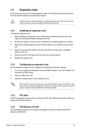
... the system and change the necessary BIOS settings, if any. Secure the card to use . 4. See Chapter 2 for later use . Unplug the power cord before adding or removing expansion cards. Remove the system unit cover (if your motherboard is completely seated on shared slots,... settings. 1. Assign an IRQ to install expansion cards. 1.5 Expansion slots In the future, you may cause you physical injury and damage motherboard components. 1.5.1 Installing an expansion card To install an expansion card: 1. Replace the system cover. 1.5.2 Configuring an expansion card After installing the...
... the system and change the necessary BIOS settings, if any. Secure the card to use . 4. See Chapter 2 for later use . Unplug the power cord before adding or removing expansion cards. Remove the system unit cover (if your motherboard is completely seated on shared slots,... settings. 1. Assign an IRQ to install expansion cards. 1.5 Expansion slots In the future, you may cause you physical injury and damage motherboard components. 1.5.1 Installing an expansion card To install an expansion card: 1. Replace the system cover. 1.5.2 Configuring an expansion card After installing the...
User Manual
Page 23
...panel audio module to this connector to avail of the chassis intrusion sensor or switch cable to [AC97]. Connect one end of the motherboard's high-definition audio capability. • If you want to connect a high-definition front panel audio module to this connector, set ...5VSB_MB Chassis Signal GND P5G41T-M LX2/GB/LPT P5G41T-M LX2/GB/LPT Chassis intrusion connector Chapter 1: Product introduction 1-14 The signal is for details. 9. If you want to connect an AC'97 front panel audio module to this connector, set the Front Panel Type item in the BIOS setup to [HD Audio...
...panel audio module to this connector to avail of the chassis intrusion sensor or switch cable to [AC97]. Connect one end of the motherboard's high-definition audio capability. • If you want to connect a high-definition front panel audio module to this connector, set ...5VSB_MB Chassis Signal GND P5G41T-M LX2/GB/LPT P5G41T-M LX2/GB/LPT Chassis intrusion connector Chapter 1: Product introduction 1-14 The signal is for details. 9. If you want to connect an AC'97 front panel audio module to this connector, set the Front Panel Type item in the BIOS setup to [HD Audio...
User Manual
Page 26
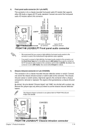
...; applications before you to avoid network traffic, or click Auto Select then click Next. From the dropdown list, select any of the original motherboard BIOS file to a USB flash disk in case you want to download then click Next. 2-1 ASUS P5G41T-M LX2 Series c. The Drivers menu appears. 2. From the Windows® desktop, click Start > Programs...
...; applications before you to avoid network traffic, or click Auto Select then click Next. From the dropdown list, select any of the original motherboard BIOS file to a USB flash disk in case you want to download then click Next. 2-1 ASUS P5G41T-M LX2 Series c. The Drivers menu appears. 2. From the Windows® desktop, click Start > Programs...
User Manual
Page 28
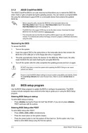
... if you do not press , POST continues with motherboard models. For motherboards without the floppy connector, prepare a USB flash disk before using the first two options. 2-3 ASUS P5G41T-M LX2 Series Entering BIOS Setup at startup To enter BIOS Setup at www.asus.com. • The removable devices that ASUS CrashFree BIOS support vary with its parameters. The utility automatically checks...
... if you do not press , POST continues with motherboard models. For motherboards without the floppy connector, prepare a USB flash disk before using the first two options. 2-3 ASUS P5G41T-M LX2 Series Entering BIOS Setup at startup To enter BIOS Setup at www.asus.com. • The removable devices that ASUS CrashFree BIOS support vary with its parameters. The utility automatically checks...
User Manual
Page 29
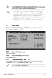
... Menu. • The BIOS setup screens shown in .] This item is for P5G41T-M LX2/GB/LPT only. Using the power button, reset button, or the ++ keys to force reset from the operating system. • The default BIOS settings for this motherboard. 2.3 Main menu When you enter the BIOS Setup program, the Main ... system properly from a running operating system can cause damage to your screen. • Visit the ASUS website at www.asus.com to download the latest BIOS file for this motherboard apply for reference purposes only, and may not exactly match what you an overview of floppy drive ...
... Menu. • The BIOS setup screens shown in .] This item is for P5G41T-M LX2/GB/LPT only. Using the power button, reset button, or the ++ keys to force reset from the operating system. • The default BIOS settings for this motherboard. 2.3 Main menu When you enter the BIOS Setup program, the Main ... system properly from a running operating system can cause damage to your screen. • Visit the ASUS website at www.asus.com to download the latest BIOS file for this motherboard apply for reference purposes only, and may not exactly match what you an overview of floppy drive ...

User Manual
Page 37
...the CPU Q-Fan function. Configuration options: [Disabled] [Enabled] Chapter 2: BIOS information 2-12 Configuration options: [Power Off] [Power On] [Last State] Power On By RTC Alarm [Disabled] Enables or disables RTC to the motherboard, the field shows [N/A]. This feature requires an ATX power supply that ...xxxºF] or [Ignored] MB Temperature [xxxºC/xxxºF] or [Ignored] The onboard hardware monitor automatically detects and displays the motherboard and CPU temperatures. 2.5.4 APM Configuration Restore on AC Power Loss [Power Off] When this item is set to [Power Off], the...
...the CPU Q-Fan function. Configuration options: [Disabled] [Enabled] Chapter 2: BIOS information 2-12 Configuration options: [Power Off] [Power On] [Last State] Power On By RTC Alarm [Disabled] Enables or disables RTC to the motherboard, the field shows [N/A]. This feature requires an ATX power supply that ...xxxºF] or [Ignored] MB Temperature [xxxºC/xxxºF] or [Ignored] The onboard hardware monitor automatically detects and displays the motherboard and CPU temperatures. 2.5.4 APM Configuration Restore on AC Power Loss [Power Off] When this item is set to [Power Off], the...

