User Manual
Page 1
Motherboard P5G41T-M LX V2 P5G41T-M LX PLUS
Motherboard P5G41T-M LX V2 P5G41T-M LX PLUS
User Manual
Page 3
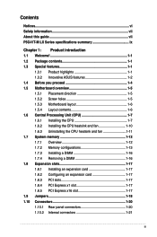
Contents Notices...vi Safety information vii About this guide vii P5G41T-M LX Series specifications summary ix Chapter 1: Product introduction 1.1 Welcome 1-1 1.2 Package contents 1-1 1.3 Special features 1-1 1.3.1 Product highlights 1-1 1.3.2 Innovative ASUS features 1-2 1.4 Before you proceed 1-4 1.5 Motherboard overview 1-5 1.5.1 Placement direction 1-5 1.5.2 Screw holes 1-5 1.5.3 Motherboard layout 1-6 1.5.4 Layout contents 1-6 1.6 Central Processing Unit (CPU 1-7 1.6.1 Installing the CPU 1-7 1.6.2 Installing the CPU heatsink and fan 1-10...
Contents Notices...vi Safety information vii About this guide vii P5G41T-M LX Series specifications summary ix Chapter 1: Product introduction 1.1 Welcome 1-1 1.2 Package contents 1-1 1.3 Special features 1-1 1.3.1 Product highlights 1-1 1.3.2 Innovative ASUS features 1-2 1.4 Before you proceed 1-4 1.5 Motherboard overview 1-5 1.5.1 Placement direction 1-5 1.5.2 Screw holes 1-5 1.5.3 Motherboard layout 1-6 1.5.4 Layout contents 1-6 1.6 Central Processing Unit (CPU 1-7 1.6.1 Installing the CPU 1-7 1.6.2 Installing the CPU heatsink and fan 1-10...
User Manual
Page 11
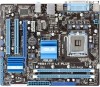
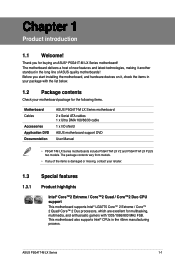
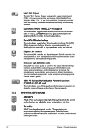
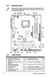
... enthusiastic gamers with the list below. 1.2 Package contents Check your package with 1333/1066/800 MHz FSB. Before you for the following items. Motherboard Cables Accessories Application DVD Documentation ASUS P5G41T-M LX Series motherboard 2 x Serial ATA cables 1 x Ultra DMA 100/66/33 cable 1 x I/O shield ASUS motherboard support DVD User Manual • P5G41T-M LX Series motherboards include P5G41T-M LX V2 and P5G41T-M LX PLUS two models.
... enthusiastic gamers with the list below. 1.2 Package contents Check your package with 1333/1066/800 MHz FSB. Before you for the following items. Motherboard Cables Accessories Application DVD Documentation ASUS P5G41T-M LX Series motherboard 2 x Serial ATA cables 1 x Ultra DMA 100/66/33 cable 1 x I/O shield ASUS motherboard support DVD User Manual • P5G41T-M LX Series motherboards include P5G41T-M LX V2 and P5G41T-M LX PLUS two models.
User Manual
Page 12
... mutli-core CPUs. Serial ATA 3Gb/s technology This motherboard supports hard drives based on the headphone while playing multichannel network games. 100% All High-quality Conductive Polymer Capacitors (P5G41T-M LX PLUS only) This motherboard uses all high-quality conductive polymer capacitors for durability,... improved lifespan, and enhanced thermal capacity. Turbo Key ASUS Turbo Key allows you easy setup, Turbo Key boosts...
... mutli-core CPUs. Serial ATA 3Gb/s technology This motherboard supports hard drives based on the headphone while playing multichannel network games. 100% All High-quality Conductive Polymer Capacitors (P5G41T-M LX PLUS only) This motherboard uses all high-quality conductive polymer capacitors for durability,... improved lifespan, and enhanced thermal capacity. Turbo Key ASUS Turbo Key allows you easy setup, Turbo Key boosts...
User Manual
Page 13
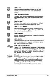
... the motherboard from damage caused by power surges from switching power supply (PSU). ASUS EZ Flash 2 ASUS EZ Flash 2 is European Union´s Energy-related Products (ErP) ready, and ErP requires products to meet certain energy efficiency requirements in line with ASUS vision... automatically restores the CPU parameters to 100 meters at 1 meter accuracy. ASUS AI NET2 ASUS AI NET2 remotely detects the cable connection immediately after turning on your screen. ASUS P5G41T-M LX Series 1-3 ASUS Q-Fan ASUS Q-Fan technology intelligently adjusts the CPU fan speed according to system loading ...
... the motherboard from damage caused by power surges from switching power supply (PSU). ASUS EZ Flash 2 ASUS EZ Flash 2 is European Union´s Energy-related Products (ErP) ready, and ErP requires products to meet certain energy efficiency requirements in line with ASUS vision... automatically restores the CPU parameters to 100 meters at 1 meter accuracy. ASUS AI NET2 ASUS AI NET2 remotely detects the cable connection immediately after turning on your screen. ASUS P5G41T-M LX Series 1-3 ASUS Q-Fan ASUS Q-Fan technology intelligently adjusts the CPU fan speed according to system loading ...
User Manual
Page 14
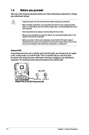
... wall socket before you uninstall any component, place it on them due to static electricity. • Hold components by the edges to the motherboard, peripherals, or components. 1.4 Before you proceed Take note of the onboard LED. The illustration below shows the location of the following precautions ... power cable before removing or plugging in the bag that came with the component. • Before you install or remove any motherboard settings. • Unplug the power cord from the power supply. P5G41T-M LX PLUS Onboard LED P5G41T-M LX PLUS 1-4 Chapter 1: Product introduction
... wall socket before you uninstall any component, place it on them due to static electricity. • Hold components by the edges to the motherboard, peripherals, or components. 1.4 Before you proceed Take note of the onboard LED. The illustration below shows the location of the following precautions ... power cable before removing or plugging in the bag that came with the component. • Before you install or remove any motherboard settings. • Unplug the power cord from the power supply. P5G41T-M LX PLUS Onboard LED P5G41T-M LX PLUS 1-4 Chapter 1: Product introduction
User Manual
Page 15
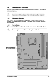
... as indicated in the correct orientation. The edge with external ports goes to the rear part of the chassis P5G41T-M LX PLUS ASUS P5G41T-M LX Series 1-5 Failure to the chassis. 1.5 Motherboard overview Before you place it . Ensure that the motherboard fits into it into the chassis in the image below. 1.5.2 Screw holes Place six screws into the holes...
... as indicated in the correct orientation. The edge with external ports goes to the rear part of the chassis P5G41T-M LX PLUS ASUS P5G41T-M LX Series 1-5 Failure to the chassis. 1.5 Motherboard overview Before you place it . Ensure that the motherboard fits into it into the chassis in the image below. 1.5.2 Screw holes Place six screws into the holes...
User Manual
Page 16
...) 3. IDE connector (40-1 pin PRI_IDE) 8. CPU and chassis fan connectors (4-pin CPU_FAN, 3-pin CHA_FAN) 5. 1.5.3 Motherboard layout ASUS P5G41T-M LX Series motherboards include P5G41T-M LX V2 and P5G41T-M LX PLUS two models. The layout illustrations in this user guide are for P5G41T-M LX PLUS only. 20.1cm(7.9in) COM1 P5G41T-M LX PLUS RTL 8111E ICS 9LRS954A4 9 15 14 13 12 11 10 1.5.4 Layout contents Connectors/Jumpers/Slots...
...) 3. IDE connector (40-1 pin PRI_IDE) 8. CPU and chassis fan connectors (4-pin CPU_FAN, 3-pin CHA_FAN) 5. 1.5.3 Motherboard layout ASUS P5G41T-M LX Series motherboards include P5G41T-M LX V2 and P5G41T-M LX PLUS two models. The layout illustrations in this user guide are for P5G41T-M LX PLUS only. 20.1cm(7.9in) COM1 P5G41T-M LX PLUS RTL 8111E ICS 9LRS954A4 9 15 14 13 12 11 10 1.5.4 Layout contents Connectors/Jumpers/Slots...
User Manual
Page 17
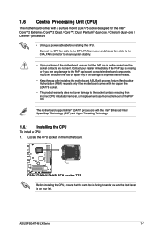
...ASUS P5G41T-M LX Series 1-7 ASUS will shoulder the cost of repair only if the damage is on the motherboard. P5G41T-M LX PLUS P5G41T-M LX PLUS CPU socket 775 Before installing the CPU, ensure that the PnP cap is facing towards you see any damage to the PnP cap/socket contacts/motherboard components. 1.6 Central Processing Unit (CPU) The motherboard...the cam box is on the socket and the socket contacts are not bent. ASUS will process Return Merchandise Authorization (RMA) requests only if the motherboard comes with the Intel® Enhanced Intel SpeedStep® Technology (EIST) and...
...ASUS P5G41T-M LX Series 1-7 ASUS will shoulder the cost of repair only if the damage is on the motherboard. P5G41T-M LX PLUS P5G41T-M LX PLUS CPU socket 775 Before installing the CPU, ensure that the PnP cap is facing towards you see any damage to the PnP cap/socket contacts/motherboard components. 1.6 Central Processing Unit (CPU) The motherboard...the cam box is on the socket and the socket contacts are not bent. ASUS will process Return Merchandise Authorization (RMA) requests only if the motherboard comes with the Intel® Enhanced Intel SpeedStep® Technology (EIST) and...
User Manual
Page 21
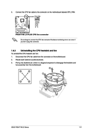
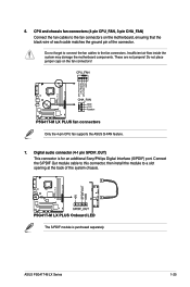
Pull up two fasteners at a time in a diagonal sequence to the connector on the motherboard. 2. Disconnect the CPU fan cable from the motherboard. P5G41T-M LX PLUS P5G41T-M LX PLUS CPU fan connector Do not forget to plug this connector. 1.6.3 Uninstalling the CPU heatsink and fan To uninstall the CPU heatsink and fan: ...to connect the CPU fan connector! 3. Connect the CPU fan cable to disengage the heatsink and fan assembly from the connector on the motherboard labeled CPU_FAN. Rotate each fastener counterclockwise. 3. A A B B B A B A ASUS P5G41T-M LX Series 1-11
Pull up two fasteners at a time in a diagonal sequence to the connector on the motherboard. 2. Disconnect the CPU fan cable from the motherboard. P5G41T-M LX PLUS P5G41T-M LX PLUS CPU fan connector Do not forget to plug this connector. 1.6.3 Uninstalling the CPU heatsink and fan To uninstall the CPU heatsink and fan: ...to connect the CPU fan connector! 3. Connect the CPU fan cable to disengage the heatsink and fan assembly from the connector on the motherboard labeled CPU_FAN. Rotate each fastener counterclockwise. 3. A A B B B A B A ASUS P5G41T-M LX Series 1-11
User Manual
Page 22
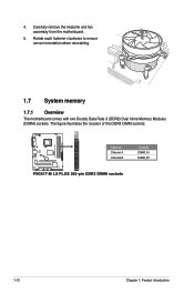
Carefully remove the heatsink and fan assembly from the motherboard. 5. Rotate each fastener clockwise to ensure correct orientation when reinstalling. 1.7 System memory 1.7.1 Overview The motherboard comes with two Double Data Rate 3 (DDR3) Dual Inline Memory Modules (DIMM) sockets. 4. The figure illustrates the location of the DDR3 DIMM sockets: P5G41T-M LX PLUS Channel Channel A Channel B P5G41T-M LX PLUS 240-pin DDR3 DIMM sockets Sockets DIMM_A1 DIMM_B1 1-12 Chapter 1: Product introduction
Carefully remove the heatsink and fan assembly from the motherboard. 5. Rotate each fastener clockwise to ensure correct orientation when reinstalling. 1.7 System memory 1.7.1 Overview The motherboard comes with two Double Data Rate 3 (DDR3) Dual Inline Memory Modules (DIMM) sockets. 4. The figure illustrates the location of the DDR3 DIMM sockets: P5G41T-M LX PLUS Channel Channel A Channel B P5G41T-M LX PLUS 240-pin DDR3 DIMM sockets Sockets DIMM_A1 DIMM_B1 1-12 Chapter 1: Product introduction
User Manual
Page 23
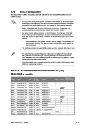
... M2Y2G64CBHA9N-BE 2048MB DS - - 7-7-7-20 - • • Kingtiger 2GB DIMM PC3-8500 2048MB DS Hynix H5TQ1G83AFP G7C - - • • ASUS P5G41T-M LX Series 1-13 1.7.2 Memory configurations You may install 512MB, 1GB, 2GB, and 4GB unbuffered non‑ECC DDR3 DIMMs into the DIMM sockets. • You ... memory from a memory module. For effective use a more efficient cooling system to install 4GB or more memory on the motherboard. • This motherboard does not support DIMMs made up of 256 megabits (Mb) chips or less. • The default memory operation frequency ...
... M2Y2G64CBHA9N-BE 2048MB DS - - 7-7-7-20 - • • Kingtiger 2GB DIMM PC3-8500 2048MB DS Hynix H5TQ1G83AFP G7C - - • • ASUS P5G41T-M LX Series 1-13 1.7.2 Memory configurations You may install 512MB, 1GB, 2GB, and 4GB unbuffered non‑ECC DDR3 DIMMs into the DIMM sockets. • You ... memory from a memory module. For effective use a more efficient cooling system to install 4GB or more memory on the motherboard. • This motherboard does not support DIMMs made up of 256 megabits (Mb) chips or less. • The default memory operation frequency ...
User Manual
Page 27
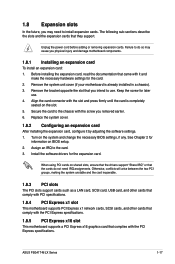
Secure the card to the chassis with the screw you physical injury and damage motherboard components. 1.8.1 Installing an expansion card To install an expansion card: 1. ASUS P5G41T-M LX Series 1-17 Failure to do not need to install expansion cards. Remove the bracket opposite...sub‑sections describe the slots and the expansion cards that complies with the PCI Express specifications. 1.8.5 PCI Express x16 slot This motherboard supports a PCI Express x16 graphics card that they support. Replace the system cover. 1.8.2 Configuring an expansion card After installing the ...
Secure the card to the chassis with the screw you physical injury and damage motherboard components. 1.8.1 Installing an expansion card To install an expansion card: 1. ASUS P5G41T-M LX Series 1-17 Failure to do not need to install expansion cards. Remove the bracket opposite...sub‑sections describe the slots and the expansion cards that complies with the PCI Express specifications. 1.8.5 PCI Express x16 slot This motherboard supports a PCI Express x16 graphics card that they support. Replace the system cover. 1.8.2 Configuring an expansion card After installing the ...
User Manual
Page 31
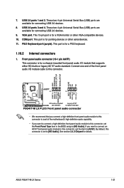
... devices. 9. These two 4-pin Universal Serial Bus (USB) ports are available for a PS/2 keyboard. 1.10.2 Internal connectors 1. P5G41T-M LX PLUS Front panel audio connector • We recommend that supports either HD Audio or legacy AC`97 audio standard. VGA port. Front panel audio.... 8. P5G41T-M LX PLUS ASUS P5G41T-M LX Series 1-21 COM port. By default, this connector, set to [AC97]. USB 2.0 ports 1 and 2. Connect one end of the front panel audio I /O module that you connect a high-definition front panel audio module to this connector to avail of the motherboard's high-...
... devices. 9. These two 4-pin Universal Serial Bus (USB) ports are available for a PS/2 keyboard. 1.10.2 Internal connectors 1. P5G41T-M LX PLUS Front panel audio connector • We recommend that supports either HD Audio or legacy AC`97 audio standard. VGA port. Front panel audio.... 8. P5G41T-M LX PLUS ASUS P5G41T-M LX Series 1-21 COM port. By default, this connector, set to [AC97]. USB 2.0 ports 1 and 2. Connect one end of the front panel audio I /O module that you connect a high-definition front panel audio module to this connector to avail of the motherboard's high-...

User Manual
Page 32
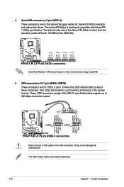
... insertion when you connect the IDE cable. • Use the 80-conductor IDE cable for the Ultra DMA 100/66/33 signal cable. P5G41T-M LX PLUS P5G41T-M LX PLUS IDE connector If any device jumper is for Ultra DMA 100/66/33 IDE devices. There are three connectors on the IDE connector is removed... to configure your device. Connect the blue connector to the motherboard's IDE connector, then select one of device(s) Master Slave Master Slave Cable connector Black Black Gray Black or gray • Pin 20 on ...
... insertion when you connect the IDE cable. • Use the 80-conductor IDE cable for the Ultra DMA 100/66/33 signal cable. P5G41T-M LX PLUS P5G41T-M LX PLUS IDE connector If any device jumper is for Ultra DMA 100/66/33 IDE devices. There are three connectors on the IDE connector is removed... to configure your device. Connect the blue connector to the motherboard's IDE connector, then select one of device(s) Master Slave Master Slave Cable connector Black Black Gray Black or gray • Pin 20 on ...
User Manual
Page 34
... MB/s (Ultra DMA133). Doing so will damage the motherboard! The USB module cable is faster than the standard parallel ATA with Serial ATA 1.5Gb/s specification. The data transfer rate of the system chassis. P5G41T-M LX PLUS P5G41T-M LX PLUS USB2.0 connectors Never connect a 1394 cable to 480...the module to a slot opening at the back of the Serial ATA 3Gb/s is purchased separately. 1-24 Chapter 1: Product introduction P5G41T-M LX PLUS SATA connectors Install the Windows® XP Service Pack 2 or later version before using Serial ATA. 5. These USB connectors comply ...
... MB/s (Ultra DMA133). Doing so will damage the motherboard! The USB module cable is faster than the standard parallel ATA with Serial ATA 1.5Gb/s specification. The data transfer rate of the system chassis. P5G41T-M LX PLUS P5G41T-M LX PLUS USB2.0 connectors Never connect a 1394 cable to 480...the module to a slot opening at the back of the Serial ATA 3Gb/s is purchased separately. 1-24 Chapter 1: Product introduction P5G41T-M LX PLUS SATA connectors Install the Windows® XP Service Pack 2 or later version before using Serial ATA. 5. These USB connectors comply ...
User Manual
Page 35
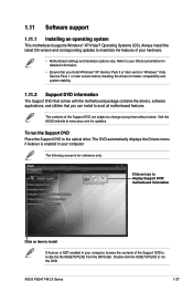
...ASUS P5G41T-M LX Series 1-25 Connect the S/PDIF Out module cable to this connector, then install the module to a slot opening at the back of the connector. P5G41T-M LX PLUS P5G41T-M LX PLUS Onboard LED The S/PDIF module is for an additional Sony/Philips Digital Interface (S/PDIF) port. Do not place jumper caps on the motherboard... separately. Insufficient air flow inside the system may damage the motherboard components. 6. P5G41T-M LX PLUS P5G41T-M LX PLUS fan connectors Only the 4-pin CPU fan supports the ASUS Q-FAN feature. 7. CPU and chassis fan connectors (4-pin CPU_FAN...
...ASUS P5G41T-M LX Series 1-25 Connect the S/PDIF Out module cable to this connector, then install the module to a slot opening at the back of the connector. P5G41T-M LX PLUS P5G41T-M LX PLUS Onboard LED The S/PDIF module is for an additional Sony/Philips Digital Interface (S/PDIF) port. Do not place jumper caps on the motherboard... separately. Insufficient air flow inside the system may damage the motherboard components. 6. P5G41T-M LX PLUS P5G41T-M LX PLUS fan connectors Only the 4-pin CPU fan supports the ASUS Q-FAN feature. 7. CPU and chassis fan connectors (4-pin CPU_FAN...
User Manual
Page 37
..., browse the contents of the Support DVD are subject to your hardware. • Motherboard settings and hardware options vary. The DVD automatically displays the Drivers menu if Autorun is for updates. ASUS P5G41T-M LX Series 1-27 To run the Support DVD Place the Support DVD to run the DVD.... Refer to change at www.asus.com for reference only. The contents of the Support DVD to avail all motherboard features. The following screen is enabled...
..., browse the contents of the Support DVD are subject to your hardware. • Motherboard settings and hardware options vary. The DVD automatically displays the Drivers menu if Autorun is for updates. ASUS P5G41T-M LX Series 1-27 To run the Support DVD Place the Support DVD to run the DVD.... Refer to change at www.asus.com for reference only. The contents of the Support DVD to avail all motherboard features. The following screen is enabled...
User Manual
Page 39
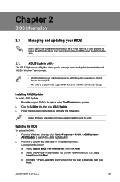
... download then click Next. c. Place the support DVD in the future. Follow the onscreen instructions to launch the ASUS Update utility. 2. ASUS P5G41T-M LX Series 2-1 Installing ASUS Update To install ASUS Update: 1. From the dropdown list, select any of the original motherboard BIOS file to a USB flash disk in case you to manage, save, and update the...
... download then click Next. c. Place the support DVD in the future. Follow the onscreen instructions to launch the ASUS Update utility. 2. ASUS P5G41T-M LX Series 2-1 Installing ASUS Update To install ASUS Update: 1. From the dropdown list, select any of the original motherboard BIOS file to a USB flash disk in case you to manage, save, and update the...
User Manual
Page 41
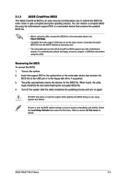
... BIOS default settings to section 2.8 Exit menu for the BIOS file. 2.1.3 ASUS CrashFree BIOS The ASUS CrashFree BIOS is an auto recovery tool that ASUS CrashFree BIOS support vary with motherboard models. Download the latest BIOS file from the ASUS website at www.asus.com. • The removable devices that allows you to restore the BIOS... system after the utility completes the updating process and turn on the system. 2. DO NOT shut down or reset the system while updating the BIOS! ASUS P5G41T-M LX Series 2-3
... BIOS default settings to section 2.8 Exit menu for the BIOS file. 2.1.3 ASUS CrashFree BIOS The ASUS CrashFree BIOS is an auto recovery tool that ASUS CrashFree BIOS support vary with motherboard models. Download the latest BIOS file from the ASUS website at www.asus.com. • The removable devices that allows you to restore the BIOS... system after the utility completes the updating process and turn on the system. 2. DO NOT shut down or reset the system while updating the BIOS! ASUS P5G41T-M LX Series 2-3


