
User Manual
Page 1
P5G41-M LX Motherboard
P5G41-M LX Motherboard
User Manual
Page 3
Contents Notices...v Safety information vi About this guide vii P5G41-M LX specifications summary viii Chapter 1: Product introduction 1.1 Before you proceed 1-1 1.2 Motherboard overview 1-2 1.2.1 Motherboard layout 1-2 1.2.2 Layout contents 1-2 1.3 Central Processing Unit (CPU 1-3 1.4 System memory 1-3 ... support 1-16 1.8.1 Installing an operating system 1-16 1.8.2 Support DVD information 1-16 Chapter 2: BIOS information 2.1 Managing and updating your BIOS 2-1 2.1.1 ASUS Update utility 2-1 2.1.2 ASUS EZ Flash 2 2-2 2.1.3 ASUS CrashFree BIOS 2-3 2.2 BIOS setup program 2-3 iii
Contents Notices...v Safety information vi About this guide vii P5G41-M LX specifications summary viii Chapter 1: Product introduction 1.1 Before you proceed 1-1 1.2 Motherboard overview 1-2 1.2.1 Motherboard layout 1-2 1.2.2 Layout contents 1-2 1.3 Central Processing Unit (CPU 1-3 1.4 System memory 1-3 ... support 1-16 1.8.1 Installing an operating system 1-16 1.8.2 Support DVD information 1-16 Chapter 2: BIOS information 2.1 Managing and updating your BIOS 2-1 2.1.1 ASUS Update utility 2-1 2.1.2 ASUS EZ Flash 2 2-2 2.1.3 ASUS CrashFree BIOS 2-3 2.2 BIOS setup program 2-3 iii
User Manual
Page 8
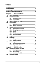
...High Definition Audio 6-channel CODEC - Supports Jack-detection and Multi-streaming technologies Supports up to www.asus.com or this user manual for Intel® CPU support list. P5G41-M LX specifications summary CPU Chipset Front Side Bus Memory Graphics Expansion slots Storage LAN Audio USB... ASUS special features LGA775 socket for Intel® Core™2 Quad / Core™2 Extreme / Core™2 Duo / Pentium® ...
...High Definition Audio 6-channel CODEC - Supports Jack-detection and Multi-streaming technologies Supports up to www.asus.com or this user manual for Intel® CPU support list. P5G41-M LX specifications summary CPU Chipset Front Side Bus Memory Graphics Expansion slots Storage LAN Audio USB... ASUS special features LGA775 socket for Intel® Core™2 Quad / Core™2 Extreme / Core™2 Duo / Pentium® ...
User Manual
Page 9
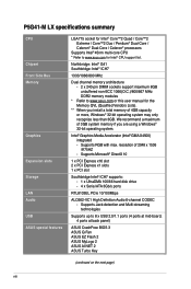
P5G41-M LX specifications summary Back panel I/O ports Internal I/O connectors BIOS features Support DVD contents Accessories Form factor 1 x PS/2 keyboard port 1 x PS/2 mouse port 1 x COM port 1 x VGA port 1 x ...-pin EATX power connector 1 x 4-pin ATX 12V power connector 8Mb Flash ROM, AMI BIOS, PnP, DMI 2.0, WfM 2.0, ACPI v2.0a, SM BIOS v2.5 Drivers ASUS PC Probe II ASUS LiveUpdate Utility Anti-virus software (OEM version) 2 x Serial ATA cables 1 x UltraDMA 100/66 cable 1 x I/O shield User Manual MicroATX form factor: 9.6 in x 7.2 in (24...
P5G41-M LX specifications summary Back panel I/O ports Internal I/O connectors BIOS features Support DVD contents Accessories Form factor 1 x PS/2 keyboard port 1 x PS/2 mouse port 1 x COM port 1 x VGA port 1 x ...-pin EATX power connector 1 x 4-pin ATX 12V power connector 8Mb Flash ROM, AMI BIOS, PnP, DMI 2.0, WfM 2.0, ACPI v2.0a, SM BIOS v2.5 Drivers ASUS PC Probe II ASUS LiveUpdate Utility Anti-virus software (OEM version) 2 x Serial ATA cables 1 x UltraDMA 100/66 cable 1 x I/O shield User Manual MicroATX form factor: 9.6 in x 7.2 in (24...
User Manual
Page 10
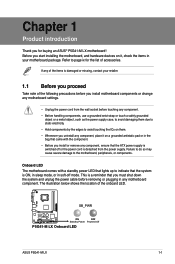
... avoid touching the ICs on them due to static electricity. • Hold components by the edges to page ix for buying an ASUS® P5G41-M LX motherboard! Failure to do so may cause severe damage to indicate that the system is ON, in sleep mode, or in your ...cord is damaged or missing, contact your motherboard package. The illustration below shows the location of accessories. SB_PWR P5G41-M LX ON OFF Standby Power Powered Off P5G41-M LX Onboard LED ASUS P5G41-M LX 1-1 If any of the items is detached from the wall socket before removing or plugging in the bag ...
... avoid touching the ICs on them due to static electricity. • Hold components by the edges to page ix for buying an ASUS® P5G41-M LX motherboard! Failure to do so may cause severe damage to indicate that the system is ON, in sleep mode, or in your ...cord is damaged or missing, contact your motherboard package. The illustration below shows the location of accessories. SB_PWR P5G41-M LX ON OFF Standby Power Powered Off P5G41-M LX Onboard LED ASUS P5G41-M LX 1-1 If any of the items is detached from the wall socket before removing or plugging in the bag ...
User Manual
Page 11
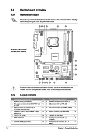
...-4 LAN1_USB12 LGA775 Intel® G41 24.4cm(9.6in) EATXPWR AUDIO 2 RTL 8103EL PCIEX16 ICS 9LRS954 7 Super I/O PCIEX1_1 Lithium Cell CMOS Power Intel® 8 ICH7 PCIEX1_2 P5G41-M LX SATA2 SATA4 CLRTC 8Mb 8 BIOS ALC PCI1 SATA1 SATA3 662-VC1 SB_PWR F_PANEL USBPW5-8 USB78 USB56 PRI_IDE AAFP SPEAKER 14 13 12 11 4 10 9 Place...
...-4 LAN1_USB12 LGA775 Intel® G41 24.4cm(9.6in) EATXPWR AUDIO 2 RTL 8103EL PCIEX16 ICS 9LRS954 7 Super I/O PCIEX1_1 Lithium Cell CMOS Power Intel® 8 ICH7 PCIEX1_2 P5G41-M LX SATA2 SATA4 CLRTC 8Mb 8 BIOS ALC PCI1 SATA1 SATA3 662-VC1 SB_PWR F_PANEL USBPW5-8 USB78 USB56 PRI_IDE AAFP SPEAKER 14 13 12 11 4 10 9 Place...

User Manual
Page 12
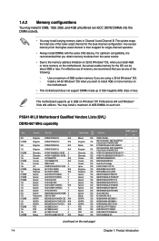
... on the LGA775 socket. • The product warranty does not cover damage to the PnP cap/socket contacts/motherboard components. ASUS will shoulder the cost of repair only if the damage is shipment/transit-related. • Keep the cap after installing the...removal, or misplacement/loss/incorrect removal of the DDR2 DIMM sockets: DIMM_A1 DIMM_B1 Channel Channel A Channel B P5G41-M LX P5G41-M LX 240-pin DDR2 DIMM sockets Sockets DIMM_A1 DIMM_B1 ASUS P5G41-M LX 1-3 ASUS will process Return Merchandise Authorization (RMA) requests only if the motherboard comes with the cap on the ...
... on the LGA775 socket. • The product warranty does not cover damage to the PnP cap/socket contacts/motherboard components. ASUS will shoulder the cost of repair only if the damage is shipment/transit-related. • Keep the cap after installing the...removal, or misplacement/loss/incorrect removal of the DDR2 DIMM sockets: DIMM_A1 DIMM_B1 Channel Channel A Channel B P5G41-M LX P5G41-M LX 240-pin DDR2 DIMM sockets Sockets DIMM_A1 DIMM_B1 ASUS P5G41-M LX 1-3 ASUS will process Return Merchandise Authorization (RMA) requests only if the motherboard comes with the cap on the ...
User Manual
Page 13
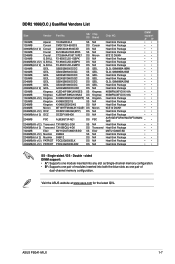
... motherboard does not support DIMMs made up to the memory address limitation on 32-bit Windows® OS, when you do any of the following: - P5G41-M LX Motherboard Qualified Vendors Lists (QVL) DDR2-667 MHz capability Size 2G 512MB 2G 1G 512MB 1G 1G 512MB 1G 1G 512MB 1G 512MB 512MB 512MB...
... motherboard does not support DIMMs made up to the memory address limitation on 32-bit Windows® OS, when you do any of the following: - P5G41-M LX Motherboard Qualified Vendors Lists (QVL) DDR2-667 MHz capability Size 2G 512MB 2G 1G 512MB 1G 1G 512MB 1G 1G 512MB 1G 512MB 512MB 512MB...
User Manual
Page 14
...-Sink Package DS Heat-Sink Package SS HY5PS12821CFP-S5 DS HY5PS12821CFPS5 • • • • • • • • • (continued on the next page) ASUS P5G41-M LX 1-5 CL 1G 1G 2G 2G 2G(2 x 1GB) 4G(2 x 2GB) 1G 512MB 4G 1G 1G 1G 512MB 512MB 1G 2G 512MB 512MB 1G 1G 512MB 1G...
...-Sink Package DS Heat-Sink Package SS HY5PS12821CFP-S5 DS HY5PS12821CFPS5 • • • • • • • • • (continued on the next page) ASUS P5G41-M LX 1-5 CL 1G 1G 2G 2G 2G(2 x 1GB) 4G(2 x 2GB) 1G 512MB 4G 1G 1G 1G 512MB 512MB 1G 2G 512MB 512MB 1G 1G 512MB 1G...
User Manual
Page 16
... DS Chip Brand N/A Corsair N/A N/A Micron N/A N/A N/A GEIL GEIL GEIL GEIL GEIL GEIL N/A Kingmax Kingmax Kingston N/A N/A Micron N/A N/A PSC N/A Transcend Elixir N/A N/A N/A N/A DIMM Chip NO. Double - ASUS P5G41-M LX 1-7 Visit the ASUS website at www.asus.com for the latest QVL. SS/ DS 1024MB Apacer 1024MB Corsair 4096MB(kit of 2) Corsair 1024MB Crucial 2048MB Crucial 1024MB G.SKILL 2048MB(Kit...
... DS Chip Brand N/A Corsair N/A N/A Micron N/A N/A N/A GEIL GEIL GEIL GEIL GEIL GEIL N/A Kingmax Kingmax Kingston N/A N/A Micron N/A N/A PSC N/A Transcend Elixir N/A N/A N/A N/A DIMM Chip NO. Double - ASUS P5G41-M LX 1-7 Visit the ASUS website at www.asus.com for the latest QVL. SS/ DS 1024MB Apacer 1024MB Corsair 4096MB(kit of 2) Corsair 1024MB Crucial 2048MB Crucial 1024MB G.SKILL 2048MB(Kit...
User Manual
Page 18
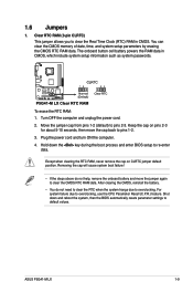
... will cause system boot failure! • If the steps above do not need to clear the RTC when the system hangs due to default values. ASUS P5G41-M LX 1-9 Turn OFF the computer and unplug the power cord. 2. For system failure due to pins 2-3. 1.6 Jumpers 1. To erase the RTC RAM: 1. Hold down and reboot...
... will cause system boot failure! • If the steps above do not need to clear the RTC when the system hangs due to default values. ASUS P5G41-M LX 1-9 Turn OFF the computer and unplug the power cord. 2. For system failure due to pins 2-3. 1.6 Jumpers 1. To erase the RTC RAM: 1. Hold down and reboot...
User Manual
Page 19
USBPW1-4 12 23 +5V +5VSB (Default) USBPW5-8 12 23 P5G41-M LX +5V +5VSB (Default) P5G41-M LX USB Device Wake Up 1.7 Connectors 1.7.1 Rear panel connectors 1 2 34 10 9 1-10 8 7 6 5 Chapter 1: Product introduction Set to +5VSB to wake up the computer by pressing a key ... KBPWR) This jumper allows you can supply at least 1A on the keyboard (the default is the Space Bar)s. KBPWR 12 23 +5V +5VSB (Default) P5G41-M LX P5G41-M LX Keyboard Power Setting 3.
USBPW1-4 12 23 +5V +5VSB (Default) USBPW5-8 12 23 P5G41-M LX +5V +5VSB (Default) P5G41-M LX USB Device Wake Up 1.7 Connectors 1.7.1 Rear panel connectors 1 2 34 10 9 1-10 8 7 6 5 Chapter 1: Product introduction Set to +5VSB to wake up the computer by pressing a key ... KBPWR) This jumper allows you can supply at least 1A on the keyboard (the default is the Space Bar)s. KBPWR 12 23 +5V +5VSB (Default) P5G41-M LX P5G41-M LX Keyboard Power Setting 3.
User Manual
Page 20
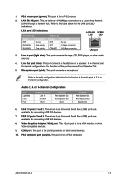
... Bus (USB) ports are available for pointing devices or other audio sources. 4. This 15-pin port is for connecting USB 2.0 devices. 7. PS/2 keyboard port (purple). ASUS P5G41-M LX 1-11 Line In port (light blue). In 4-channel and 6-channel configurations, the function of the audio ports in 2, 4, or 6-channel configuration. This port is for...
... Bus (USB) ports are available for pointing devices or other audio sources. 4. This 15-pin port is for connecting USB 2.0 devices. 7. PS/2 keyboard port (purple). ASUS P5G41-M LX 1-11 Line In port (light blue). In 4-channel and 6-channel configurations, the function of the audio ports in 2, 4, or 6-channel configuration. This port is for...
User Manual
Page 21
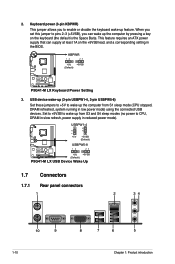
... The fan connectors support cooling fans of 350 mA~740 mA (8.88 W max.) or a total of 1 A~2.22 A (26.64 W max.) at http://support.asus. P5G41-M LX fan connectors 1-12 Chapter 1: Product introduction Find the proper orientation and push down firmly until the connectors completely fit. Connect the fan cables to install... fan connectors. com/PowerSupplyCalculator/PSCalculator.aspx?SLanguage=en-us for your system, refer to fit these connectors in only one orientation. P5G41-M LX CPU_FAN GND CPU FAN PWR CPU FAN IN CPU FAN PWM CHA_FAN GND +12V Rotation Only the 4-pin CPU fan supports the...
... The fan connectors support cooling fans of 350 mA~740 mA (8.88 W max.) or a total of 1 A~2.22 A (26.64 W max.) at http://support.asus. P5G41-M LX fan connectors 1-12 Chapter 1: Product introduction Find the proper orientation and push down firmly until the connectors completely fit. Connect the fan cables to install... fan connectors. com/PowerSupplyCalculator/PSCalculator.aspx?SLanguage=en-us for your system, refer to fit these connectors in only one orientation. P5G41-M LX CPU_FAN GND CPU FAN PWR CPU FAN IN CPU FAN PWM CHA_FAN GND +12V Rotation Only the 4-pin CPU fan supports the...
User Manual
Page 22
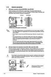
...motherboard's IDE connector, then select one of the following modes to match the covered hole on the Ultra DMA cable connector. PRI_IDE P5G41-M LX PIN1 NOTE:Orient the red markings on each Ultra DMA 100/66 signal cable: blue, black, and gray. Serial ATA connectors... RSATA_TXP3 GND SATA1 SATA3 SATA4 GND RSATA_TXP4 RSATA_TXN4 GND RSATA_RXP4 RSATA_RXN4 GND SATA2 GND RSATA_TXP2 RSATA_TXN2 GND RSATA_RXP2 RSATA_RXN2 GND P5G41-M LX SATA connectors ASUS P5G41-M LX 1-13 Single device Two devices Drive jumper setting Cable-Select or Master Cable-Select Master Slave Mode of the Serial...
...motherboard's IDE connector, then select one of the following modes to match the covered hole on the Ultra DMA cable connector. PRI_IDE P5G41-M LX PIN1 NOTE:Orient the red markings on each Ultra DMA 100/66 signal cable: blue, black, and gray. Serial ATA connectors... RSATA_TXP3 GND SATA1 SATA3 SATA4 GND RSATA_TXP4 RSATA_TXN4 GND RSATA_RXP4 RSATA_RXN4 GND SATA2 GND RSATA_TXP2 RSATA_TXN2 GND RSATA_RXP2 RSATA_RXN2 GND P5G41-M LX SATA connectors ASUS P5G41-M LX 1-13 Single device Two devices Drive jumper setting Cable-Select or Master Cable-Select Master Slave Mode of the Serial...
User Manual
Page 23
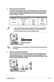
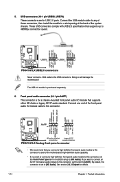
...speed. USB+5V USB_P6USB_P6+ GND NC USB+5V USB_P8USB_P8+ GND NC USB+5V USB_P5USB_P5+ GND USB+5V USB_P7USB_P7+ GND P5G41-M LX USB78 PIN 1 USB56 PIN 1 P5G41-M LX USB2.0 connectors Never connect a 1394 cable to [HD Audio]. GND PRESENCE# SENSE1_RETUR SENSE2_RETUR AGND NC NC NC AAFP PIN... 1 PIN 1 MIC2 MICPWR Line out_R NC Line out_L PORT1 L PORT1 R PORT2 R SENSE_SEND PORT2 L P5G41-M LX HD-audio-compliant Legacy AC'97 pin definition compliant definition P5G41-M LX Analog front panel connector • We recommend that supports up to [HD Audio]. By default, this connector...
...speed. USB+5V USB_P6USB_P6+ GND NC USB+5V USB_P8USB_P8+ GND NC USB+5V USB_P5USB_P5+ GND USB+5V USB_P7USB_P7+ GND P5G41-M LX USB78 PIN 1 USB56 PIN 1 P5G41-M LX USB2.0 connectors Never connect a 1394 cable to [HD Audio]. GND PRESENCE# SENSE1_RETUR SENSE2_RETUR AGND NC NC NC AAFP PIN... 1 PIN 1 MIC2 MICPWR Line out_R NC Line out_L PORT1 L PORT1 R PORT2 R SENSE_SEND PORT2 L P5G41-M LX HD-audio-compliant Legacy AC'97 pin definition compliant definition P5G41-M LX Analog front panel connector • We recommend that supports up to [HD Audio]. By default, this connector...
User Manual
Page 24
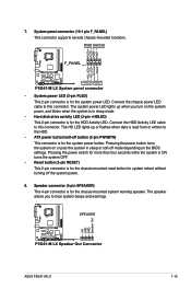
...; System power LED (2-pin PLED) This 2-pin connector is read from or written to hear system beeps and warnings. SPEAKER P5G41-M LX PIN 1 P5G41-M LX Speaker Out Connector +5V GND GND Speaker Out ASUS P5G41-M LX 1-15 The system power LED lights up or flashes when data is for the chassis-mounted system warning speaker. Pressing the...
...; System power LED (2-pin PLED) This 2-pin connector is read from or written to hear system beeps and warnings. SPEAKER P5G41-M LX PIN 1 P5G41-M LX Speaker Out Connector +5V GND GND Speaker Out ASUS P5G41-M LX 1-15 The system power LED lights up or flashes when data is for the chassis-mounted system warning speaker. Pressing the...
User Manual
Page 26
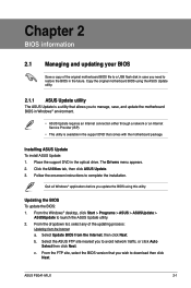
...site, select the BIOS version that you to manage, save, and update the motherboard BIOS in the future. ASUS P5G41-M LX 2-1 Installing ASUS Update To install ASUS Update: 1. Quit all Windows® applications before you to avoid network traffic, or click Auto Select then click...you update the BIOS using this utility. Follow the onscreen instructions to launch the ASUS Update utility. 2. b. Copy the original motherboard BIOS using the ASUS Update utility. 2.1.1 ASUS Update utility The ASUS Update is available in the optical drive. Chapter 2 BIOS information 2.1 Managing ...
...site, select the BIOS version that you to manage, save, and update the motherboard BIOS in the future. ASUS P5G41-M LX 2-1 Installing ASUS Update To install ASUS Update: 1. Quit all Windows® applications before you to avoid network traffic, or click Auto Select then click...you update the BIOS using this utility. Follow the onscreen instructions to launch the ASUS Update utility. 2. b. Copy the original motherboard BIOS using the ASUS Update utility. 2.1.1 ASUS Update utility The ASUS Update is available in the optical drive. Chapter 2 BIOS information 2.1 Managing ...
User Manual
Page 27
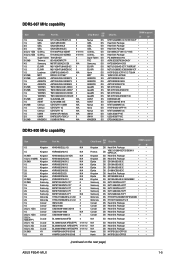
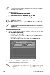
... utility is found . Follow the onscreen instructions to complete the updating process. 2.1.2 ASUS EZ Flash 2 The ASUS EZ Flash 2 feature allows you start using EZ Flash 2: 1. ASUSTek EZ Flash 2 BIOS ROM Utility V3.36 FLASH TYPE: MXIC 25L8005 Current ROM BOARD: P5G41-M-LX VER: 0307 (H:00 B:01) DATE: 07/21/2009 Update ROM BOARD...
... utility is found . Follow the onscreen instructions to complete the updating process. 2.1.2 ASUS EZ Flash 2 The ASUS EZ Flash 2 feature allows you start using EZ Flash 2: 1. ASUSTek EZ Flash 2 BIOS ROM Utility V3.36 FLASH TYPE: MXIC 25L8005 Current ROM BOARD: P5G41-M-LX VER: 0307 (H:00 B:01) DATE: 07/21/2009 Update ROM BOARD...
User Manual
Page 28
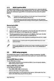
.... • The removable devices that contains the updated BIOS file. • The BIOS file in using the BIOS Setup program. ASUS P5G41-M LX 2-3 When found, the utility reads the BIOS file and starts flashing the corrupted BIOS file. 4. Refer to section 2.8 Exit menu for ... simultaneously. • Press the reset button on the system chassis. • Press the power button to ensure system compatibility and stability. 2.1.3 ASUS CrashFree BIOS The ASUS CrashFree BIOS is an auto recovery tool that contains the BIOS file to the USB port or to the floppy disk drive, if supported...
.... • The removable devices that contains the updated BIOS file. • The BIOS file in using the BIOS Setup program. ASUS P5G41-M LX 2-3 When found, the utility reads the BIOS file and starts flashing the corrupted BIOS file. 4. Refer to section 2.8 Exit menu for ... simultaneously. • Press the reset button on the system chassis. • Press the power button to ensure system compatibility and stability. 2.1.3 ASUS CrashFree BIOS The ASUS CrashFree BIOS is an auto recovery tool that contains the BIOS file to the USB port or to the floppy disk drive, if supported...


