User Manual
Page 4
Contents 1.11 Software support 1-32 1.11.1 Installing an operating system 1-32 1.11.2 Support DVD information 1-32 Chapter 2: BIOS information 2.1 Managing and updating your BIOS 2-1 2.1.1 ASUS Update utility 2-1 2.1.2 ASUS EZ Flash 2 utility 2-2 2.1.3 ASUS CrashFree BIOS 3 utility 2-3 2.2 BIOS setup program 2-4 2.2.1 BIOS menu screen 2-5 2.2.2 Menu bar 2-5 2.2.3 Navigation keys 2-6 2.2.4 Menu items 2-6 2.2.5 Submenu items 2-6 2.2.6 Configuration fields 2-6 2.2.7 Pop-up window 2-6 2.2.8 Scroll bar 2-6 2.2.9 General help 2-6 2.3 Main...
Contents 1.11 Software support 1-32 1.11.1 Installing an operating system 1-32 1.11.2 Support DVD information 1-32 Chapter 2: BIOS information 2.1 Managing and updating your BIOS 2-1 2.1.1 ASUS Update utility 2-1 2.1.2 ASUS EZ Flash 2 utility 2-2 2.1.3 ASUS CrashFree BIOS 3 utility 2-3 2.2 BIOS setup program 2-4 2.2.1 BIOS menu screen 2-5 2.2.2 Menu bar 2-5 2.2.3 Navigation keys 2-6 2.2.4 Menu items 2-6 2.2.5 Submenu items 2-6 2.2.6 Configuration fields 2-6 2.2.7 Pop-up window 2-6 2.2.8 Scroll bar 2-6 2.2.9 General help 2-6 2.3 Main...
User Manual
Page 8
... of the motherboard and the new technology it supports. • Chapter 2: BIOS information This chapter tells how to select. ASUS websites The ASUS website provides updated information on ASUS hardware and software products. Keys enclosed in this guide To make sure that you...keys simultaneously, the key names are linked with a plus sign (+). Example: ++ viii Where to complete a task. Used to the ASUS contact information. 2. Example: means that may have been added by your dealer. These documents are also provided. Typography Bold text Italics ++...
... of the motherboard and the new technology it supports. • Chapter 2: BIOS information This chapter tells how to select. ASUS websites The ASUS website provides updated information on ASUS hardware and software products. Keys enclosed in this guide To make sure that you...keys simultaneously, the key names are linked with a plus sign (+). Example: ++ viii Where to complete a task. Used to the ASUS contact information. 2. Example: means that may have been added by your dealer. These documents are also provided. Typography Bold text Italics ++...
User Manual
Page 10
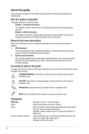
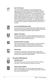
P5G41-M LE specifications summary ASUS Special Features ASUS CrashFree BIOS 3 ASUS Q-Fan ASUS EZ Flash 2 ASUS MyLogo 2 ASUS AI NET2 ASUS EPU-L ASUS Turbo Key ASUS Anti-Surge Protection Back Panel I/O Ports 1 x PS/2 keyboard port 1 x PS/2 mouse port 1 x DVI port 1 x VGA port 1 x LAN (RJ-45) ... 1 x 24-pin EATX power connector 1 x 4-pin ATX 12V power connector BIOS features 8Mb Flash ROM, AMI BIOS, PnP, DMI v2.0, WfM 2.0, ACPI v2.0a, SM BIOS v2.5 Support DVD Contents Drivers ASUS PC Probe II ASUS LiveUpdate Utility Anti-virus software (OEM version) Accessories 2 x Serial ATA cables 1...
P5G41-M LE specifications summary ASUS Special Features ASUS CrashFree BIOS 3 ASUS Q-Fan ASUS EZ Flash 2 ASUS MyLogo 2 ASUS AI NET2 ASUS EPU-L ASUS Turbo Key ASUS Anti-Surge Protection Back Panel I/O Ports 1 x PS/2 keyboard port 1 x PS/2 mouse port 1 x DVI port 1 x VGA port 1 x LAN (RJ-45) ... 1 x 24-pin EATX power connector 1 x 4-pin ATX 12V power connector BIOS features 8Mb Flash ROM, AMI BIOS, PnP, DMI v2.0, WfM 2.0, ACPI v2.0a, SM BIOS v2.5 Support DVD Contents Drivers ASUS PC Probe II ASUS LiveUpdate Utility Anti-virus software (OEM version) Accessories 2 x Serial ATA cables 1...
User Manual
Page 12
... bus bandwidth for high-speed data saving and retrieval. DVI Interface DVI (Digital Visual Interface) provides high quality of both DVI-D/HDMI and RGB. ASUS CrashFree BIOS 3 ASUS CrashFree BIOS 3 is enhanced with the next-generation Intel® Graphics Media Acceleratior X4500. It also supports the Windows® Vista Premium OS. Shader Model 4.0 and...
... bus bandwidth for high-speed data saving and retrieval. DVI Interface DVI (Digital Visual Interface) provides high quality of both DVI-D/HDMI and RGB. ASUS CrashFree BIOS 3 ASUS CrashFree BIOS 3 is enhanced with the next-generation Intel® Graphics Media Acceleratior X4500. It also supports the Windows® Vista Premium OS. Shader Model 4.0 and...
User Manual
Page 13
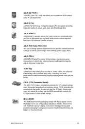
... Simply shut down and reboot the system, and the BIOS automatically restores the CPU parameters to overclocking failure. ASUS EZ Flash 2 ASUS EZ Flash 2 is in real-time. C.P.R. (CPU Parameter Recall) The BIOS C.P.R. After the easy setup, Turbo Key can boost ...ASUS AI NET2 ASUS AI NET2 remotely detects the cable connection immediately after you to update the BIOS without interrupting ongoing work or games-with the European Union's Restriction on the environment. This is a utility that allows you turn the PC power button into a physical overclocking button. ASUS P5G41-M LE...
... Simply shut down and reboot the system, and the BIOS automatically restores the CPU parameters to overclocking failure. ASUS EZ Flash 2 ASUS EZ Flash 2 is in real-time. C.P.R. (CPU Parameter Recall) The BIOS C.P.R. After the easy setup, Turbo Key can boost ...ASUS AI NET2 ASUS AI NET2 remotely detects the cable connection immediately after you to update the BIOS without interrupting ongoing work or games-with the European Union's Restriction on the environment. This is a utility that allows you turn the PC power button into a physical overclocking button. ASUS P5G41-M LE...
User Manual
Page 16
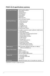
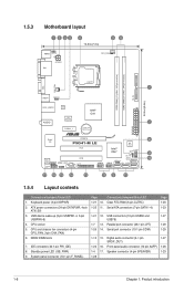
...(9.6in) LAN1_USB12 Atheros L1E Intel® G41 ICS 9LRS954 AUDIO 2 PCIEX1_1 Lithium Cell CMOS Power EATXPWR Super I/O PCIEX16 P5G41-M LE PCI1 RTL Audio codec SPEAKER SPDIF_OUT COM1 AAFP PCI2 LPT USB56 Intel® ICH7 8Mb BIOS F_PANEL CLRTC USB78 SB_PWR USBPW5-8 SATA4 SATA3 SATA1 SATA2 8 9 10 17 16 15 14 13 12 3 11...
...(9.6in) LAN1_USB12 Atheros L1E Intel® G41 ICS 9LRS954 AUDIO 2 PCIEX1_1 Lithium Cell CMOS Power EATXPWR Super I/O PCIEX16 P5G41-M LE PCI1 RTL Audio codec SPEAKER SPDIF_OUT COM1 AAFP PCI2 LPT USB56 Intel® ICH7 8Mb BIOS F_PANEL CLRTC USB78 SB_PWR USBPW5-8 SATA4 SATA3 SATA1 SATA2 8 9 10 17 16 15 14 13 12 3 11...
User Manual
Page 31
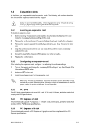
...the card connector with the PCI Express specifications. Turn on the slot. 5. See Chapter 2 for later use . When using PCI cards on BIOS setup. 2. ASUS P5G41-M LE 1-21 Keep the screw for information on shared slots, ensure that the drivers support "Share IRQ" or that you intend to install expansion ...Secure the card to the card. 3. Remove the system unit cover (if your motherboard is completely seated on the system and change the necessary BIOS settings, if any. Install the software drivers for the card. 2. 1.8 Expansion slots In the future, you may cause you physical injury and...
...the card connector with the PCI Express specifications. Turn on the slot. 5. See Chapter 2 for later use . When using PCI cards on BIOS setup. 2. ASUS P5G41-M LE 1-21 Keep the screw for information on shared slots, ensure that the drivers support "Share IRQ" or that you intend to install expansion ...Secure the card to the card. 3. Remove the system unit cover (if your motherboard is completely seated on the system and change the necessary BIOS settings, if any. Install the software drivers for the card. 2. 1.8 Expansion slots In the future, you may cause you physical injury and...

User Manual
Page 32
... the onboard battery and move the cap back to pins 1-2. 3. CLRTC 12 23 P5G41-M LE Normal (Default) P5G41-M LE Clear RTC RAM Clear RTC To erase the RTC RAM: 1. Hold down and reboot the system, then the BIOS automatically resets parameter settings to default values. • Due to the chipset limitation, ...Clock (RTC) RAM in CMOS, which include system setup information such as system passwords. Shut down the key during the boot process and enter BIOS setup to pins 2-3. The onboard button cell battery powers the RAM data in CMOS. Turn OFF the computer and unplug the power cord. ...
... the onboard battery and move the cap back to pins 1-2. 3. CLRTC 12 23 P5G41-M LE Normal (Default) P5G41-M LE Clear RTC RAM Clear RTC To erase the RTC RAM: 1. Hold down and reboot the system, then the BIOS automatically resets parameter settings to default values. • Due to the chipset limitation, ...Clock (RTC) RAM in CMOS, which include system setup information such as system passwords. Shut down the key during the boot process and enter BIOS setup to pins 2-3. The onboard button cell battery powers the RAM data in CMOS. Turn OFF the computer and unplug the power cord. ...
User Manual
Page 33
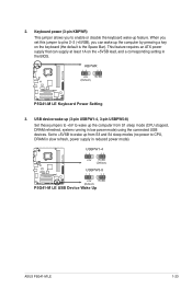
..., DRAM in slow refresh, power supply in reduced power mode). USBPW1-4 12 23 +5V +5VSB (Default) USBPW5-8 P5G41-M LE 12 23 +5V +5VSB (Default) P5G41-M LE USB Device Wake Up ASUS P5G41-M LE 1-23 KBPWR 12 23 +5V +5VSB (Default) P5G41-M LE P5G41-M LE Keyboard Power Setting 3. USB device wake-up (3-pin USBPW1-4, 3-pin USBPW5-8) Set these jumpers to +5V to... feature. When you set this jumper to pins 2-3 (+5VSB), you to wake up from S1 sleep mode (CPU stopped, DRAM refreshed, system running in the BIOS. 2.
..., DRAM in slow refresh, power supply in reduced power mode). USBPW1-4 12 23 +5V +5VSB (Default) USBPW5-8 P5G41-M LE 12 23 +5V +5VSB (Default) P5G41-M LE USB Device Wake Up ASUS P5G41-M LE 1-23 KBPWR 12 23 +5V +5VSB (Default) P5G41-M LE P5G41-M LE Keyboard Power Setting 3. USB device wake-up (3-pin USBPW1-4, 3-pin USBPW5-8) Set these jumpers to +5V to... feature. When you set this jumper to pins 2-3 (+5VSB), you to wake up from S1 sleep mode (CPU stopped, DRAM refreshed, system running in the BIOS. 2.
User Manual
Page 38
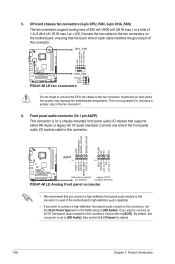
...compliant definition P5G41-M LE Analog front panel connector • We recommend that you connect a high-definition front panel audio module to this connector to [HD Audio]. If you want to connect an AC'97 front panel audio module to this connector, set the Front Panel Type item in the BIOS setup to...is set the item to the fan connectors on the fan connector! 6. CPU_FAN GND CPU FAN PWR CPU FAN IN CPU FAN PWM P5G41-M LE CHA_FAN Rotation +12V GND P5G41-M LE fan connectors Do not forget to connect the CPU fan cables to [HD Audio]. Front panel audio connector (10-1 pin AAFP) This...
...compliant definition P5G41-M LE Analog front panel connector • We recommend that you connect a high-definition front panel audio module to this connector to [HD Audio]. If you want to connect an AC'97 front panel audio module to this connector, set the Front Panel Type item in the BIOS setup to...is set the item to the fan connectors on the fan connector! 6. CPU_FAN GND CPU FAN PWR CPU FAN IN CPU FAN PWM P5G41-M LE CHA_FAN Rotation +12V GND P5G41-M LE fan connectors Do not forget to connect the CPU fan cables to [HD Audio]. Front panel audio connector (10-1 pin AAFP) This...
User Manual
Page 40
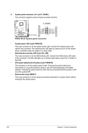
... the BIOS settings. The IDE LED lights up when you turn on or puts the system in sleep mode. • Hard disk drive activity LED (2-pin HD_LED) This 2-pin connector is for the HDD Activity LED. F_PANEL PWR LED PWR BTN HD_LED RESET P5G41-M LE GND PWR PLEDPLED+ Reset Ground IDE_LEDIDE_LED+ PIN 1 P5G41-M LE System...
... the BIOS settings. The IDE LED lights up when you turn on or puts the system in sleep mode. • Hard disk drive activity LED (2-pin HD_LED) This 2-pin connector is for the HDD Activity LED. F_PANEL PWR LED PWR BTN HD_LED RESET P5G41-M LE GND PWR PLEDPLED+ Reset Ground IDE_LEDIDE_LED+ PIN 1 P5G41-M LE System...
User Manual
Page 43
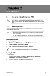
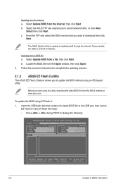
... BIOS in Windows® environment. • ASUS Update requires an Internet connection either through a network or an Internet Service Provider (ISP). • This utility is available in the optical drive. Installing ASUS Update To install ASUS Update: 1. Updating the BIOS To update the BIOS: 1. Chapter 2 BIOS information 2.1 Managing and updating your BIOS Save a copy of the updating process: ASUS P5G41-M LE...
... BIOS in Windows® environment. • ASUS Update requires an Internet connection either through a network or an Internet Service Provider (ISP). • This utility is available in the optical drive. Installing ASUS Update To install ASUS Update: 1. Updating the BIOS To update the BIOS: 1. Chapter 2 BIOS information 2.1 Managing and updating your BIOS Save a copy of the updating process: ASUS P5G41-M LE...
User Manual
Page 44
...: • Press + during POST to download then click Next. Locate the BIOS file from a BIOS file a. Select the ASUS FTP site nearest you wish to display the following: ASUSTek EZ Flash 2 BIOS ROM Utility V3.36 FLASH TYPE: WOINBOND W25X80 Current ROM BOARD: P5G41-M LE VER: 0203 (H:00 B:01) DATE: 02/24/2009 Update ROM BOARD...
...: • Press + during POST to download then click Next. Locate the BIOS file from a BIOS file a. Select the ASUS FTP site nearest you wish to display the following: ASUSTek EZ Flash 2 BIOS ROM Utility V3.36 FLASH TYPE: WOINBOND W25X80 Current ROM BOARD: P5G41-M LE VER: 0203 (H:00 B:01) DATE: 02/24/2009 Update ROM BOARD...
User Manual
Page 45
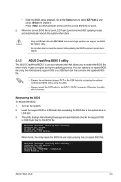
... message and automatically checks the support DVD or USB flash disk for USB Device... Bad BIOS checksum. Starting BIOS recovery... Checking for the BIOS file. Start Erasing...\ ASUS P5G41-M LE 2-3 Otherwise, the utility will not function. Checking for USB Device... Turn on the system. 2. Bad BIOS checksum. Checking for CD-ROM... When found, the utility reads the...
... message and automatically checks the support DVD or USB flash disk for USB Device... Bad BIOS checksum. Starting BIOS recovery... Checking for the BIOS file. Start Erasing...\ ASUS P5G41-M LE 2-3 Otherwise, the utility will not function. Checking for USB Device... Turn on the system. 2. Bad BIOS checksum. Checking for CD-ROM... When found, the utility reads the...

User Manual
Page 46
... Setup program, you can change the power management settings. The recovered BIOS may not be smaller than 8GB. • DO NOT shut down the system properly from the ASUS website at www.asus.com. 2.2 BIOS setup program This motherboard supports a programmable Serial Peripheral Interface (SPI)... chip that the computer can support ASUS CrashFree BIOS 3. Even if you can enable the security password feature or...
... Setup program, you can change the power management settings. The recovered BIOS may not be smaller than 8GB. • DO NOT shut down the system properly from the ASUS website at www.asus.com. 2.2 BIOS setup program This motherboard supports a programmable Serial Peripheral Interface (SPI)... chip that the computer can support ASUS CrashFree BIOS 3. Even if you can enable the security password feature or...

User Manual
Page 47
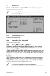
... menu bar on your screen. • Visit the ASUS website at www.asus.com to download the latest BIOS file for this motherboard. 2.2.1 BIOS menu screen Menu items Menu bar Main Advanced Power Configuration fields BIOS SETUP UTILITY Boot Tools Exit General help System Time [00...until the desired item is highlighted. ASUS P5G41-M LE 2-5 For changing the advanced power management (APM) configuration. If the system becomes unstable after changing any BIOS settings, load the default settings to configure system Time. • The default BIOS settings for this section are for ...
... menu bar on your screen. • Visit the ASUS website at www.asus.com to download the latest BIOS file for this motherboard. 2.2.1 BIOS menu screen Menu items Menu bar Main Advanced Power Configuration fields BIOS SETUP UTILITY Boot Tools Exit General help System Time [00...until the desired item is highlighted. ASUS P5G41-M LE 2-5 For changing the advanced power management (APM) configuration. If the system becomes unstable after changing any BIOS settings, load the default settings to configure system Time. • The default BIOS settings for this section are for ...
User Manual
Page 48
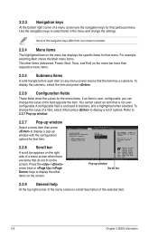
...If an item is highlighted when selected. configurable, you can change the value of options. To change the settings. Main Advanced BIOS SETUP UTILITY Power Boot Tools Exit Suspend Mode ACPI Version Features ACPI APIC support APM Configuration Hardware Monitor [Auto] [Disabled] [...EDniOsapabtbilloendesd] Enabled Use [ENTER], [TAB] or [SHIFT-TAB] to configure system Time. Some of the selected item. 2-6 Chapter 2: BIOS information Change Field Tab Select Field F1 General Help F10 Save and Exit ESC Exit v02.61 (C)Copyright 1985-2008, A m e r i c a n...
...If an item is highlighted when selected. configurable, you can change the value of options. To change the settings. Main Advanced BIOS SETUP UTILITY Power Boot Tools Exit Suspend Mode ACPI Version Features ACPI APIC support APM Configuration Hardware Monitor [Auto] [Disabled] [...EDniOsapabtbilloendesd] Enabled Use [ENTER], [TAB] or [SHIFT-TAB] to configure system Time. Some of the selected item. 2-6 Chapter 2: BIOS information Change Field Tab Select Field F1 General Help F10 Save and Exit ESC Exit v02.61 (C)Copyright 1985-2008, A m e r i c a n...
User Manual
Page 49
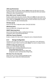
...:[Not Detected] :[Not Detected] :[Not Detected] :[Not Detected] :[Not Detected] Use [ENTER], [TAB] or [SHIFT-TAB] to display the IDE/SATA device information. The BIOS automatically detects the values opposite the dimmed items (Device, Vendor, Size, LBA Mode, Block Mode, PIO Mode, Async DMA, Ultra DMA, and SMART monitoring). Select... Select Screen Select Item +- Select ARMD (ATAPI Removable Media Device) if your device is installed in the system. Setting to navigate through them. ASUS P5G41-M LE 2-7 Refer to section 2.2.1 BIOS menu screen for each IDE/SATA device.
...:[Not Detected] :[Not Detected] :[Not Detected] :[Not Detected] :[Not Detected] Use [ENTER], [TAB] or [SHIFT-TAB] to display the IDE/SATA device information. The BIOS automatically detects the values opposite the dimmed items (Device, Vendor, Size, LBA Mode, Block Mode, PIO Mode, Async DMA, Ultra DMA, and SMART monitoring). Select... Select Screen Select Item +- Select ARMD (ATAPI Removable Media Device) if your device is installed in the system. Setting to navigate through them. ASUS P5G41-M LE 2-7 Refer to section 2.2.1 BIOS menu screen for each IDE/SATA device.
User Manual
Page 50
... Out (Sec) [35] Selects the time out value for the SATA devices installed in the system. Configuration options: [0] [5] [10] [15] [20] [25] [30] [35] 2-8 Chapter 2: BIOS information When set to [Disabled], the data transfer from and to configure the item. Configuration options: [Disabled] [Compatible] [Enhanced] Enhanced Mode Support On [S-ATA] Set...
... Out (Sec) [35] Selects the time out value for the SATA devices installed in the system. Configuration options: [0] [5] [10] [15] [20] [25] [30] [35] 2-8 Chapter 2: BIOS information When set to [Disabled], the data transfer from and to configure the item. Configuration options: [Disabled] [Compatible] [Enhanced] Enhanced Mode Support On [S-ATA] Set...
User Manual
Page 51
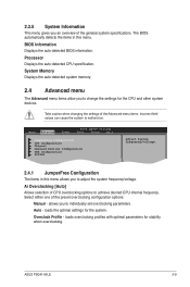
...Take caution when changing the settings of CPU overclocking options to change the settings for the CPU and other system devices. Main Advanced Power BIOS SETUP UTILITY Boot Tools Exit JumperFree Configuration CPU Configuration Chipset Onboard Devices Configuration USB Configuration PCIPnP Adjust System frequency/voltage. 2.4.1 JumperFree Configuration The... either one of the general system specifications. allows you to malfunction. loads overclocking profiles with optimal parameters for the system. The BIOS automatically detects the items in this menu. ASUS P5G41-M LE 2-9
...Take caution when changing the settings of CPU overclocking options to change the settings for the CPU and other system devices. Main Advanced Power BIOS SETUP UTILITY Boot Tools Exit JumperFree Configuration CPU Configuration Chipset Onboard Devices Configuration USB Configuration PCIPnP Adjust System frequency/voltage. 2.4.1 JumperFree Configuration The... either one of the general system specifications. allows you to malfunction. loads overclocking profiles with optimal parameters for the system. The BIOS automatically detects the items in this menu. ASUS P5G41-M LE 2-9


