Motherboard Installation Guide
Page 4
... 3-2 3.2.1 Using the OS shut down function 3-2 3.2.2 Using the dual function power switch 3-2 Chapter 4: BIOS setup 4.1 Managing and updating your BIOS 4-1 4.1.1 ASUS Update utility 4-1 4.1.2 Creating a bootable floppy disk 4-4 4.1.3 ASUS EZ Flash 2 utility 4-5 4.1.4 AFUDOS utility 4-6 4.1.5 ASUS CrashFree BIOS 3 utility 4-8 4.2 BIOS setup program 4-9 4.2.1 BIOS menu screen 4-10 4.2.2 Menu bar 4-10 4.2.3 Navigation keys 4-10 4.2.4 Menu items 4-11...
... 3-2 3.2.1 Using the OS shut down function 3-2 3.2.2 Using the dual function power switch 3-2 Chapter 4: BIOS setup 4.1 Managing and updating your BIOS 4-1 4.1.1 ASUS Update utility 4-1 4.1.2 Creating a bootable floppy disk 4-4 4.1.3 ASUS EZ Flash 2 utility 4-5 4.1.4 AFUDOS utility 4-6 4.1.5 ASUS CrashFree BIOS 3 utility 4-8 4.2 BIOS setup program 4-9 4.2.1 BIOS menu screen 4-10 4.2.2 Menu bar 4-10 4.2.3 Navigation keys 4-10 4.2.4 Menu items 4-11...
Motherboard Installation Guide
Page 7
AI Gear 3 5-20 5.3.6 ASUS AI Nap 5-21 5.3.7 ASUS Q-Fan 2 5-22 5.3.8 ASUS AI Booster 5-23 5.3.9 AI Audio 2 (SoundMAX® High Definition Audio utility)... 5-24 5.4 RAID configurations 5-33 5.4.1 ...RAID definitions 5-33 5.4.2 Installing Serial ATA hard disks 5-34 5.4.3 Intel® RAID configurations 5-34 5.5 Creating a RAID driver disk 5-44 5.5.1 Creating a RAID driver disk without entering the OS.... 5-44 5.5.2 Creating a RAID/SATA driver disk in Windows...
AI Gear 3 5-20 5.3.6 ASUS AI Nap 5-21 5.3.7 ASUS Q-Fan 2 5-22 5.3.8 ASUS AI Booster 5-23 5.3.9 AI Audio 2 (SoundMAX® High Definition Audio utility)... 5-24 5.4 RAID configurations 5-33 5.4.1 ...RAID definitions 5-33 5.4.2 Installing Serial ATA hard disks 5-34 5.4.3 Intel® RAID configurations 5-34 5.5 Creating a RAID driver disk 5-44 5.5.1 Creating a RAID driver disk without entering the OS.... 5-44 5.5.2 Creating a RAID/SATA driver disk in Windows...

Motherboard Installation Guide
Page 34
... socket to remove (B). DO NOT force the CPU into the CPU notch. Refer to ensure system stability. B A Load plate Alignment key 5. The motherboard supports Intel® LGA775 processors with your thumb and forefinger to a 100º angle (A), then push the PnP cap from the load plate... window to prevent bending the connectors on these CPU features. 2-8 Chapter 2: Hardware information Close the load plate (A), then A push the load lever (B) until...
... socket to remove (B). DO NOT force the CPU into the CPU notch. Refer to ensure system stability. B A Load plate Alignment key 5. The motherboard supports Intel® LGA775 processors with your thumb and forefinger to a 100º angle (A), then push the PnP cap from the load plate... window to prevent bending the connectors on these CPU features. 2-8 Chapter 2: Hardware information Close the load plate (A), then A push the load lever (B) until...

Motherboard Installation Guide
Page 40
... Memory Configurations Mode DIMM_A1 Sockets DIMM_A2 DIMM_B1 DIMM_B2 Populated - - - Due to chipset limitation, this motherboard can only support up of 2 GB DIMMs on Windows® Vista 32-bit / Windows® XP 32-bit operation systems since it is recommended that you obtain memory modules from the ...higher-sized channel is recommended. • This motherboard does not support memory modules made up to...
... Memory Configurations Mode DIMM_A1 Sockets DIMM_A2 DIMM_B1 DIMM_B2 Populated - - - Due to chipset limitation, this motherboard can only support up of 2 GB DIMMs on Windows® Vista 32-bit / Windows® XP 32-bit operation systems since it is recommended that you obtain memory modules from the ...higher-sized channel is recommended. • This motherboard does not support memory modules made up to...

Motherboard Installation Guide
Page 68
... then select Turn Off Computer. 2. Click the Start button then select ShutDown. 2. The power supply should turn off after Windows® shuts down the computer. 3. If you are using Windows® XP or later version: 1. Refer to soft-off mode, depending on the BIOS setting. 3.2 Turning off the ...computer 3.2.1 Using the OS shut down function If you are using Windows® Vista: 1. The power supply should turn off after Windows® shuts down. 3.2.2 Using the dual function power switch While the system is ON, pressing the power switch ...
... then select Turn Off Computer. 2. Click the Start button then select ShutDown. 2. The power supply should turn off after Windows® shuts down the computer. 3. If you are using Windows® XP or later version: 1. Refer to soft-off mode, depending on the BIOS setting. 3.2 Turning off the ...computer 3.2.1 Using the OS shut down function If you are using Windows® Vista: 1. The power supply should turn off after Windows® shuts down. 3.2.2 Using the dual function power switch While the system is ON, pressing the power switch ...
Motherboard Installation Guide
Page 71
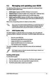
... ASUS Update VX.XX.XX. 3. ASUS P5E64 WS Evolution 4-1 The ASUS Update utility allows you need to manage and update the motherboard Basic Input/Output System (BIOS) setup. 1. ASUS Update (Updates the BIOS in the optical drive. ASUS ...Windows® environment. ASUS EZ Flash 2 (Updates the BIOS using a bootable floppy disk.) 4. Installing ASUS Update To install ASUS Update: 1. The ASUS Update utility is a utility that comes with the motherboard package. ASUS CrashFree BIOS 3 (Updates the BIOS using the ASUS Update or AFUDOS utilities. 4.1.1 ASUS Update utility The ASUS...
... ASUS Update VX.XX.XX. 3. ASUS P5E64 WS Evolution 4-1 The ASUS Update utility allows you need to manage and update the motherboard Basic Input/Output System (BIOS) setup. 1. ASUS Update (Updates the BIOS in the optical drive. ASUS ...Windows® environment. ASUS EZ Flash 2 (Updates the BIOS using a bootable floppy disk.) 4. Installing ASUS Update To install ASUS Update: 1. The ASUS Update utility is a utility that comes with the motherboard package. ASUS CrashFree BIOS 3 (Updates the BIOS using the ASUS Update or AFUDOS utilities. 4.1.1 ASUS Update utility The ASUS...
Motherboard Installation Guide
Page 72
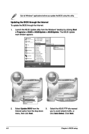
Select Update BIOS from the drop‑down you update the BIOS using this utility. Select the ASUS FTP site nearest Internet option from the 3. The ASUS Update main window appears. 2. click Auto Select. Launch the ASUS Update utility from the Windows® desktop by clicking Start > Programs > ASUS > ASUSUpdate > ASUSUpdate. Updating the BIOS through the Internet To update the BIOS through the Internet: 1. Quit all Windows® applications before you to avoid network traffic, or menu, then click Next. Click Next. 4-2 Chapter 4: BIOS setup
Select Update BIOS from the drop‑down you update the BIOS using this utility. Select the ASUS FTP site nearest Internet option from the 3. The ASUS Update main window appears. 2. click Auto Select. Launch the ASUS Update utility from the Windows® desktop by clicking Start > Programs > ASUS > ASUSUpdate > ASUSUpdate. Updating the BIOS through the Internet To update the BIOS through the Internet: 1. Quit all Windows® applications before you to avoid network traffic, or menu, then click Next. Click Next. 4-2 Chapter 4: BIOS setup

Motherboard Installation Guide
Page 73
.... 2. Follow the screen instructions to complete the update process. Select Update BIOS from a file option from the Windows® desktop by clicking Start > Programs > ASUS > ASUSUpdate > ASUSUpdate. P5E64WP.ROM P5E64WP ASUS P5E64 WS Evolution 4-3 Updating the BIOS through a BIOS file To update the BIOS through the Internet. From the FTP site, select the BIOS version that...
.... 2. Follow the screen instructions to complete the update process. Select Update BIOS from a file option from the Windows® desktop by clicking Start > Programs > ASUS > ASUSUpdate > ASUSUpdate. P5E64WP.ROM P5E64WP ASUS P5E64 WS Evolution 4-3 Updating the BIOS through a BIOS file To update the BIOS through the Internet. From the FTP site, select the BIOS version that...
Motherboard Installation Guide
Page 74
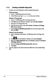
... Right-click Floppy Disk Drive then click Format to the floppy disk drive. Insert a 1.44MB floppy disk into the drive. Windows® XP environment a. d. Copy the original or the latest motherboard BIOS file to create a bootable floppy disk. Select Create an MS-DOS startup disk from the... Windows® desktop, then select Computer. Click from the format options field, then click Start. b. Click Start from...
... Right-click Floppy Disk Drive then click Format to the floppy disk drive. Insert a 1.44MB floppy disk into the drive. Windows® XP environment a. d. Copy the original or the latest motherboard BIOS file to create a bootable floppy disk. Select Create an MS-DOS startup disk from the... Windows® desktop, then select Computer. Click from the format options field, then click Start. b. Click Start from...
Motherboard Installation Guide
Page 81
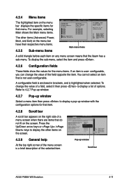
...not user-configurable. configurable, you can change the value of the field opposite the item. Use [+] or [-] to display a pop-up window Scroll bar ASUS P5E64 WS Evolution 4-11 To display the sub-menu, select the item and press . 4.2.6 Configuration fields These fields show the values for that menu. A... Detected] [Not Detected] Main menu items Use [ENTER], [TAB], or [SHIFT-TAB] to display a list of the selected item. Pop-up window with the configuration options for that item. 4.2.8 Scroll bar A scroll bar appears on the right side of a menu screen when there are items that...
...not user-configurable. configurable, you can change the value of the field opposite the item. Use [+] or [-] to display a pop-up window Scroll bar ASUS P5E64 WS Evolution 4-11 To display the sub-menu, select the item and press . 4.2.6 Configuration fields These fields show the values for that menu. A... Detected] [Not Detected] Main menu items Use [ENTER], [TAB], or [SHIFT-TAB] to display a list of the selected item. Pop-up window with the configuration options for that item. 4.2.8 Scroll bar A scroll bar appears on the right side of a menu screen when there are items that...
Motherboard Installation Guide
Page 112
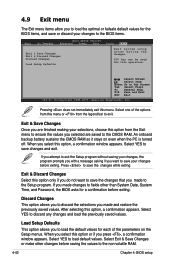
...this option only if you do not want to save your changes, the program prompts you with a message asking if you press , a confirmation window appears. 4.9 Exit menu The Exit menu items allow you made to the Setup program. An onboard backup battery sustains the CMOS RAM so it stays... on the Setup menus. Exit & Discard Changes Select this option, a confirmation window appears. Select YES to load default values. Select Exit & Save Changes or make other than System Date, System Time, and Password, the BIOS asks...
...this option only if you do not want to save your changes, the program prompts you with a message asking if you press , a confirmation window appears. 4.9 Exit menu The Exit menu items allow you made to the Setup program. An onboard backup battery sustains the CMOS RAM so it stays... on the Setup menus. Exit & Discard Changes Select this option, a confirmation window appears. Select YES to load default values. Select Exit & Save Changes or make other than System Date, System Time, and Password, the BIOS asks...
Motherboard Installation Guide
Page 115
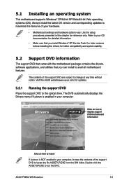
...motherboard features. Double-click the ASSETUP.EXE to locate the file ASSETUP.EXE from the BIN folder. ASUS P5E64 WS Evolution 5-1 Always install the latest OS version and corresponding updates to maximize the features of your OS documentation for detailed information. • Make sure that you install Windows... DVD information The support DVD that came with the motherboard package contains the drivers, software applications, and utilities that you can install to the optical drive. Visit the ASUS website(www.asus.com) for reference only. The DVD automatically displays the...
...motherboard features. Double-click the ASSETUP.EXE to locate the file ASSETUP.EXE from the BIN folder. ASUS P5E64 WS Evolution 5-1 Always install the latest OS version and corresponding updates to maximize the features of your OS documentation for detailed information. • Make sure that you install Windows... DVD information The support DVD that came with the motherboard package contains the drivers, software applications, and utilities that you can install to the optical drive. Visit the ASUS website(www.asus.com) for reference only. The DVD automatically displays the...
Motherboard Installation Guide
Page 123
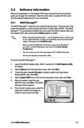
... own boot logo image in the Support DVD have wizards that appears on screen during the Power‑On Self-Tests (POST). The ASUS MyLogo window appears. 6. 5.3 Software information Most of your original BIOS file, or obtain the latest BIOS version from the drop down menu, then...BMP file formats. • The file size should be smaller than 150 K. From the left window pane, select the folder that came with the software application for details. 2. ASUS P��5�E�6�4��W��S��E�v�o�lu�t&#...
... own boot logo image in the Support DVD have wizards that appears on screen during the Power‑On Self-Tests (POST). The ASUS MyLogo window appears. 6. 5.3 Software information Most of your original BIOS file, or obtain the latest BIOS version from the drop down menu, then...BMP file formats. • The file size should be smaller than 150 K. From the left window pane, select the folder that came with the software application for details. 2. ASUS P��5�E�6�4��W��S��E�v�o�lu�t&#...
Motherboard Installation Guide
Page 124
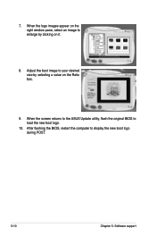
7. After flashing the BIOS, restart the computer to load the new boot logo. 10. When the screen returns to the ASUS Update utility, flash the original BIOS to display the new boot logo during POST. 5-10 Chapter 5: Software support Adjust the boot image to enlarge by selecting a value on it. 8. When the logo images appear on the right window pane, select an image to your desired size by clicking on the Ratio box. 9.
7. After flashing the BIOS, restart the computer to load the new boot logo. 10. When the screen returns to the ASUS Update utility, flash the original BIOS to display the new boot logo during POST. 5-10 Chapter 5: Software support Adjust the boot image to enlarge by selecting a value on it. 8. When the logo images appear on the right window pane, select an image to your desired size by clicking on the Ratio box. 9.

Motherboard Installation Guide
Page 125
ASUS P��5�E�6�4��W��S��... Ethernet cables connected to Gigabit LAN port(s). • The Run button on the Virtual Cable Tester™ main window is disabled if no problem is a cable diagnostic utility that reports LAN cable faults and shorts using the Time ...Domain Reflectometry (TDR) technology. Click Virtual Cable Tester from the Windows® desktop by clicking Start > All Programs > Marvell > Virtual Cable Tester. 2. The VCT detects and reports open...
ASUS P��5�E�6�4��W��S��... Ethernet cables connected to Gigabit LAN port(s). • The Run button on the Virtual Cable Tester™ main window is disabled if no problem is a cable diagnostic utility that reports LAN cable faults and shorts using the Time ...Domain Reflectometry (TDR) technology. Click Virtual Cable Tester from the Windows® desktop by clicking Start > All Programs > Marvell > Virtual Cable Tester. 2. The VCT detects and reports open...

Motherboard Installation Guide
Page 126
...; taskbar. Launching PC Probe II You can launch the PC Probe II right after installation or anytime from the Windows® desktop, click Start > All Programs > ASUS > PC Probe II > PC Probe II v1.xx.xx. After launching the application, the PC Probe II icon appears in your system and change the... is software-based, you of the Support DVD to locate the setup.exe file from the ASUS PC Probe II folder. Using PC Probe II Main window The PC Probe II main window allows you turn it on. 5.3.3 ASUS PC Probe II PC Probe II is always at a healthy operating condition. PC Probe II...
...; taskbar. Launching PC Probe II You can launch the PC Probe II right after installation or anytime from the Windows® desktop, click Start > All Programs > ASUS > PC Probe II > PC Probe II v1.xx.xx. After launching the application, the PC Probe II icon appears in your system and change the... is software-based, you of the Support DVD to locate the setup.exe file from the ASUS PC Probe II folder. Using PC Probe II Main window The PC Probe II main window allows you turn it on. 5.3.3 ASUS PC Probe II PC Probe II is always at a healthy operating condition. PC Probe II...

Motherboard Installation Guide
Page 127
... also turns red. ASUS P��5�E�6�4��W��S��E�v�o�lu�t�io�n� 5-13 Button Function Opens the Configuration window Opens the Report window Opens the Desktop Management Interface window Opens the Peripheral Component Interconnect window Opens the Windows Management Instrumentation window Opens the hard disk...
... also turns red. ASUS P��5�E�6�4��W��S��E�v�o�lu�t�io�n� 5-13 Button Function Opens the Configuration window Opens the Report window Opens the Desktop Management Interface window Opens the Peripheral Component Interconnect window Opens the Windows Management Instrumentation window Opens the hard disk...

Motherboard Installation Guide
Page 128
... the monitor panels All monitor panels move or reposition the panel independently. Adjusting the sensor threshold value You can now move together using the Config window. Click to increase value Click to detach a monitor panel from the list box. Hardware monitor panels The hardware monitor panels display the current value of...
... the monitor panels All monitor panels move or reposition the panel independently. Adjusting the sensor threshold value You can now move together using the Config window. Click to increase value Click to detach a monitor panel from the list box. Hardware monitor panels The hardware monitor panels display the current value of...
Motherboard Installation Guide
Page 129
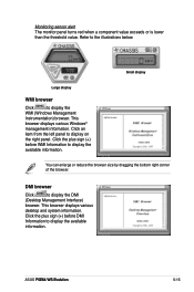
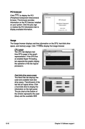
...the plus sign (+) before DMI Information to display the WMI (Windows Management Instrumentation) browser. Click an item from the left panel to display the DMI (Desktop Management Interface) browser. ASUS P��5�E�6�4��W��S��... Click to display on the right panel. This browser displays various desktop and system information. This browser displays various Windows® management information. Refer to display the available information. You can enlarge or reduce the browser size by dragging...
...the plus sign (+) before DMI Information to display the WMI (Windows Management Instrumentation) browser. Click an item from the left panel to display the DMI (Desktop Management Interface) browser. ASUS P��5�E�6�4��W��S��... Click to display on the right panel. This browser displays various desktop and system information. This browser displays various Windows® management information. Refer to display the available information. You can enlarge or reduce the browser size by dragging...
Motherboard Installation Guide
Page 130
Click a hard disk drive to display available information. The pie chart at the bottom of the window represents the used and available hard disk drive space. Usage The Usage browser displays real-time information on your system. This browser provides information on ...
Click a hard disk drive to display available information. The pie chart at the bottom of the window represents the used and available hard disk drive space. Usage The Usage browser displays real-time information on your system. This browser provides information on ...


