
Motherboard Installation Guide
Page 3
... Notices...viii Safety information ix About this guide x P5E64 WS Evolution specifications xii Chapter 1: Product introduction 1.1 Welcome 1-1 1.2 Package contents 1-1 1.3 Special features 1-2 1.3.1 Product highlights 1-2 1.3.2 ASUS special features 1-4 1.3.3 ASUS stylish features 1-7 1.3.4 ASUS intelligent overclocking features 1-7 Chapter 2: Hardware information 2.1 Before you proceed 2-1 2.2 Motherboard overview 2-2 2.2.1 Placement direction 2-2 2.2.2 Screw holes 2-2 2.2.3 Motherboard layout 2-3 2.2.4 Layout contents 2-4 2.3 Central Processing Unit (CPU 2-6 2.3.1 Installing...
... Notices...viii Safety information ix About this guide x P5E64 WS Evolution specifications xii Chapter 1: Product introduction 1.1 Welcome 1-1 1.2 Package contents 1-1 1.3 Special features 1-2 1.3.1 Product highlights 1-2 1.3.2 ASUS special features 1-4 1.3.3 ASUS stylish features 1-7 1.3.4 ASUS intelligent overclocking features 1-7 Chapter 2: Hardware information 2.1 Before you proceed 2-1 2.2 Motherboard overview 2-2 2.2.1 Placement direction 2-2 2.2.2 Screw holes 2-2 2.2.3 Motherboard layout 2-3 2.2.4 Layout contents 2-4 2.3 Central Processing Unit (CPU 2-6 2.3.1 Installing...
Motherboard Installation Guide
Page 12
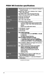
...3.0 Gb/s ports with RAID 0, 1, 10, and 5 configuration Marvell® 88E8056 / 88E8001 Dual Gigabit LAN controllers - P5E64 WS Evolution specifications CPU Chipset System bus Memory Expansion slots Storage LAN High Definition audio IEEE 1394 USB LGA775 socket for Intel® CPU support list Northbridge: Intel® ...65533;u�m��e�r�a�ti�o�n�,�M��u�l�ti�- ASUS AI Audio 2 - Intel® Matrix Storage Technology Marvell® 88SE6145 SATA/PATA controller - 1 x UltraDMA 133/100 for up...
...3.0 Gb/s ports with RAID 0, 1, 10, and 5 configuration Marvell® 88E8056 / 88E8001 Dual Gigabit LAN controllers - P5E64 WS Evolution specifications CPU Chipset System bus Memory Expansion slots Storage LAN High Definition audio IEEE 1394 USB LGA775 socket for Intel® CPU support list Northbridge: Intel® ...65533;u�m��e�r�a�ti�o�n�,�M��u�l�ti�- ASUS AI Audio 2 - Intel® Matrix Storage Technology Marvell® 88SE6145 SATA/PATA controller - 1 x UltraDMA 133/100 for up...
Motherboard Installation Guide
Page 13
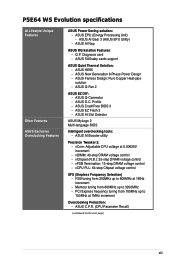
...Selection) - G.P. ASUS Q-Connector - Memory tuning from 100MHz up to 800MHz at 1MHz increment - ASUS AI Gear 3 (ASUS EPU Utility) - ASUS AI Slot Detector ASUS MyLogo 2 Multi-language BIOS Intelligent overclocking tools: - ASUS AI Nap ASUS Workstation Features: - ASUS EZ Flash 2... ASUS Fanless Design: Pure Copper Heat-pipe solution - ASUS EPU (Energy Processing Unit) - PCI Express frequency tuning from 800MHz up to 150MHz at 0.00625V increment - P5E64 WS Evolution specifications AI Lifestyle Unique Features Other Features ASUS Exclusive Overclocking Features ASUS ...
...Selection) - G.P. ASUS Q-Connector - Memory tuning from 100MHz up to 800MHz at 1MHz increment - ASUS AI Gear 3 (ASUS EPU Utility) - ASUS AI Slot Detector ASUS MyLogo 2 Multi-language BIOS Intelligent overclocking tools: - ASUS AI Nap ASUS Workstation Features: - ASUS EZ Flash 2... ASUS Fanless Design: Pure Copper Heat-pipe solution - ASUS EPU (Energy Processing Unit) - PCI Express frequency tuning from 800MHz up to 150MHz at 0.00625V increment - P5E64 WS Evolution specifications AI Lifestyle Unique Features Other Features ASUS Exclusive Overclocking Features ASUS ...

Motherboard Installation Guide
Page 18
... new feature optimizes the use of your system memory to safeguard consumers' health while minimizing the impact on the use of the most powerful CPUs in the LGA775 package. See page 2-13 for details. 1-2 Chapter 1: Product Introduction 1.3 Special features 1.3.1 Product highlights Green ASUS This motherboard and its packaging comply with the European Union...
... new feature optimizes the use of your system memory to safeguard consumers' health while minimizing the impact on the use of the most powerful CPUs in the LGA775 package. See page 2-13 for details. 1-2 Chapter 1: Product Introduction 1.3 Special features 1.3.1 Product highlights Green ASUS This motherboard and its packaging comply with the European Union...

Motherboard Installation Guide
Page 26
Diagnosis card installation 2-37 ASUS P5E64 WS Evolution Chapter summary 2 2.1 Before you proceed 2-1 2.2 Motherboard overview 2-2 2.3 Central Processing Unit (CPU 2-6 2.4 System memory 2-13 2.5 Expansion slots 2-19 2.6 Jumper 2-23 2.7 Connectors 2-24 2.8 G.P.
Diagnosis card installation 2-37 ASUS P5E64 WS Evolution Chapter summary 2 2.1 Before you proceed 2-1 2.2 Motherboard overview 2-2 2.3 Central Processing Unit (CPU 2-6 2.4 System memory 2-13 2.5 Expansion slots 2-19 2.6 Jumper 2-23 2.7 Connectors 2-24 2.8 G.P.

Motherboard Installation Guide
Page 34
... fit the socket alignment key into the retention tab. 7. Lift the load plate with the Intel® Enhanced Memory 64 Technology (EM64T), Enhanced Intel SpeedStep® Technology (EIST), and Hyper-Threading Technology. The motherboard supports Intel® LGA775 processors with your thumb and forefinger to a 100º angle (A), then push the PnP...
... fit the socket alignment key into the retention tab. 7. Lift the load plate with the Intel® Enhanced Memory 64 Technology (EM64T), Enhanced Intel SpeedStep® Technology (EIST), and Hyper-Threading Technology. The motherboard supports Intel® LGA775 processors with your thumb and forefinger to a 100º angle (A), then push the PnP...

Motherboard Installation Guide
Page 39
The figure illustrates the location of the DDR3 DIMM sockets: DIMM_A1 DIMM_A2 DIMM_B1 DIMM_B2 ® P5E64 WS EVOLUTION P5E64 WS Evolution 240-pin DDR3 DIMM sockets Channel Channel A Channel B Sockets DIMM_A1 and DIMM_A2 DIMM_B1 and DIMM_B2 ASUS P5E64 WS Evolution 2-13 DDR3 modules are developed for better performance with four Double Data Rate 3 (DDR3) Dual Inline Memory Modules (DIMM) sockets. 2.4 System memory 2.4.1 Overview The motherboard comes with less power consumption.
The figure illustrates the location of the DDR3 DIMM sockets: DIMM_A1 DIMM_A2 DIMM_B1 DIMM_B2 ® P5E64 WS EVOLUTION P5E64 WS Evolution 240-pin DDR3 DIMM sockets Channel Channel A Channel B Sockets DIMM_A1 and DIMM_A2 DIMM_B1 and DIMM_B2 ASUS P5E64 WS Evolution 2-13 DDR3 modules are developed for better performance with four Double Data Rate 3 (DDR3) Dual Inline Memory Modules (DIMM) sockets. 2.4 System memory 2.4.1 Overview The motherboard comes with less power consumption.

Motherboard Installation Guide
Page 40
...XP 32-bit operation systems since it is recommended that you obtain memory modules from the higher-sized channel is recommended. • This motherboard does not support memory modules made up to chipset limitation, this motherboard can only support up of 128 Mb chips or double sided ...x16 memory modules. Single-Channel - - Populated - You may install 512 MB, 1 GB, and...
...XP 32-bit operation systems since it is recommended that you obtain memory modules from the higher-sized channel is recommended. • This motherboard does not support memory modules made up to chipset limitation, this motherboard can only support up of 128 Mb chips or double sided ...x16 memory modules. Single-Channel - - Populated - You may install 512 MB, 1 GB, and...

Motherboard Installation Guide
Page 43
... HY5TQ1G831ZNF-S5 N/A Hynix DS HYMT125U64ZNF8-S5 • • • Side(s): SS - ASUS P5E64 WS Evolution 2-17 P5E64 WS Evolution Motherboard Qualified Vendors Lists (QVL) DDR3-800MHz capability Size Vendor Chip No. Double-sided DIMM support: • A*: Supports one module inserted into either slot as Single-channel memory configuration. • B*: Supports two modules inserted into either the blue slots or...
... HY5TQ1G831ZNF-S5 N/A Hynix DS HYMT125U64ZNF8-S5 • • • Side(s): SS - ASUS P5E64 WS Evolution 2-17 P5E64 WS Evolution Motherboard Qualified Vendors Lists (QVL) DDR3-800MHz capability Size Vendor Chip No. Double-sided DIMM support: • A*: Supports one module inserted into either slot as Single-channel memory configuration. • B*: Supports two modules inserted into either the blue slots or...

Motherboard Installation Guide
Page 49
... RTC RAM • You do not help, remove the onboard battery and move the cap back to clear the CMOS RTC RAM data. ASUS P5E64 WS Evolution 2-23 Keep the cap on pins 2-3 for about 5~10 seconds, then move the jumper again to pins 1-2. 3. Turn OFF the computer and unplug the power ... system failure due to pins 2-3. function. 2.6 Jumpers 1. To erase the RTC RAM: 1. Hold down and reboot the system so the BIOS can clear the CMOS memory of date, time, and system setup parameters by erasing the CMOS RTC RAM data. Plug the power cord and turn off is required prior using...
... RTC RAM • You do not help, remove the onboard battery and move the cap back to clear the CMOS RTC RAM data. ASUS P5E64 WS Evolution 2-23 Keep the cap on pins 2-3 for about 5~10 seconds, then move the jumper again to pins 1-2. 3. Turn OFF the computer and unplug the power ... system failure due to pins 2-3. function. 2.6 Jumpers 1. To erase the RTC RAM: 1. Hold down and reboot the system so the BIOS can clear the CMOS memory of date, time, and system setup parameters by erasing the CMOS RTC RAM data. Plug the power cord and turn off is required prior using...

Motherboard Installation Guide
Page 60
... Volts +3 Volts P5E64 WS Evolution ATX power connectors • For a fully configured system, we recommend that you are uncertain about the minimum power supply requirement for ATX power supply plugs. The power supply plugs are for your system, refer to support the motherboard power requirements with ... output is recommended when configuring a system with the following configuration: CPU: Intel® Pentium® Extreme 3.73GHz Memory: 512 MB DDR3 (x4) Graphics card: ASUS EAX1900XT Parallel ATA device: IDE hard disk drive Serial ATA device: SATA hard disk drive (x2) Optical drive: ...
... Volts +3 Volts P5E64 WS Evolution ATX power connectors • For a fully configured system, we recommend that you are uncertain about the minimum power supply requirement for ATX power supply plugs. The power supply plugs are for your system, refer to support the motherboard power requirements with ... output is recommended when configuring a system with the following configuration: CPU: Intel® Pentium® Extreme 3.73GHz Memory: 512 MB DDR3 (x4) Graphics card: ASUS EAX1900XT Parallel ATA device: IDE hard disk drive Serial ATA device: SATA hard disk drive (x2) Optical drive: ...
Motherboard Installation Guide
Page 64
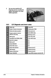
You may also install the G.P. 3. Diagnosis card via a bundled 90degree TPM adaptor for memory detection and sizing D4 Memory test D5 Copy BIOS from S4 00 Leave BIOS and pass control to OS 2-38 Chapter 2: Hardware information Diagnosis card check codes D0 Initiate chip ...
You may also install the G.P. 3. Diagnosis card via a bundled 90degree TPM adaptor for memory detection and sizing D4 Memory test D5 Copy BIOS from S4 00 Leave BIOS and pass control to OS 2-38 Chapter 2: Hardware information Diagnosis card check codes D0 Initiate chip ...
Motherboard Installation Guide
Page 67
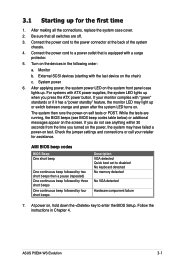
...off. 3. Follow the instructions in the following order: a. Check the jumper settings and connections or call your monitor complies with ATX power supplies, the system LED lights up when you turned on the power, the system may light up or switch between orange... power cord to disabled No keyboard detected No memory detected No VGA detected Hardware component failure 7. For systems with "green" standards or if it has a "power standby" feature, the monitor LED may have failed a power-on the screen. ASUS P5E64 WS Evolution 3-1 3.1 Starting up for assistance. Monitor b....
...off. 3. Follow the instructions in the following order: a. Check the jumper settings and connections or call your monitor complies with ATX power supplies, the system LED lights up when you turned on the power, the system may light up or switch between orange... power cord to disabled No keyboard detected No memory detected No VGA detected Hardware component failure 7. For systems with "green" standards or if it has a "power standby" feature, the monitor LED may have failed a power-on the screen. ASUS P5E64 WS Evolution 3-1 3.1 Starting up for assistance. Monitor b....

Motherboard Installation Guide
Page 86
The BIOS automatically detects the items in this menu. Processor Displays the auto-detected CPU specification. ASUS BIOS Displays the auto-detected BIOS information. System Memory Displays the auto-detected system memory. 4-16 Chapter 4: BIOS setup Main BIOS SETUP UTILITY ASUS BIOS Version : 0108 Build Date : 12/18/07 Processor Type Speed Count : Intel(R) Core...
The BIOS automatically detects the items in this menu. Processor Displays the auto-detected CPU specification. ASUS BIOS Displays the auto-detected BIOS information. System Memory Displays the auto-detected system memory. 4-16 Chapter 4: BIOS setup Main BIOS SETUP UTILITY ASUS BIOS Version : 0108 Build Date : 12/18/07 Processor Type Speed Count : Intel(R) Core...
Motherboard Installation Guide
Page 87
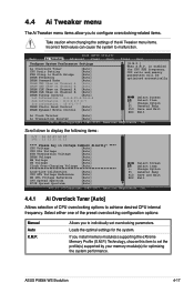
...61 (C)Copyright 1985-2007, American Megatrends, Inc. ASUS P5E64 WS Evolution 4-17 Select either one of CPU overclocking options to achieve desired CPU internal frequency. is enabled the CPU FSB frequency, CPU ratio and memory parameters will be optimized automatically Select Screen Select Item...optimal settings for optimizing the system performance. 4.4 Ai Tweaker menu The Ai Tweaker menu items allow you install memory module(s) supporting the eXtreme Memory Profile (X.M.P.) Technology, choose this item to set overclocking parameters. Scroll down to North Bridge [Auto] DRAM ...
...61 (C)Copyright 1985-2007, American Megatrends, Inc. ASUS P5E64 WS Evolution 4-17 Select either one of CPU overclocking options to achieve desired CPU internal frequency. is enabled the CPU FSB frequency, CPU ratio and memory parameters will be optimized automatically Select Screen Select Item...optimal settings for optimizing the system performance. 4.4 Ai Tweaker menu The Ai Tweaker menu items allow you install memory module(s) supporting the eXtreme Memory Profile (X.M.P.) Technology, choose this item to set overclocking parameters. Scroll down to North Bridge [Auto] DRAM ...

Motherboard Installation Guide
Page 88
...Manual]. 4-18 Chapter 4: BIOS setup To restore the default setting, type [auto] using the numeric keypad and press the key. eXtreme Memory Profile [Disabled] This item appears only when you to North Bridge [Auto] When set the ratio between CPU Core Clock and FSB ... you to set to [X.M.P.]. DIMM installation recommendation. mode supported by your Memory module. X.M.P. You can also use the and keys to the table below for the following two items (FSB Frequency and PCIE Freuency) on the motherboard. Congifuration options: [Auto] [200MHz] [266MHz] [333MHz] [400MHz]...
...Manual]. 4-18 Chapter 4: BIOS setup To restore the default setting, type [auto] using the numeric keypad and press the key. eXtreme Memory Profile [Disabled] This item appears only when you to North Bridge [Auto] When set the ratio between CPU Core Clock and FSB ... you to set to [X.M.P.]. DIMM installation recommendation. mode supported by your Memory module. X.M.P. You can also use the and keys to the table below for the following two items (FSB Frequency and PCIE Freuency) on the motherboard. Congifuration options: [Auto] [200MHz] [266MHz] [333MHz] [400MHz]...

Motherboard Installation Guide
Page 93
...78V 1.20V~1.38V 1.40V~1.50V N/A N/A 1.50V~1.68V 1.70V~1.90V 1.92V~2.10V 2.12V~2.78V 1.25V~1.41V 1.43V~1.55V 1.57V~1.73V 1.75V~2.21V* ASUS P5E64 WS Evolution 4-23 Refer to set the front side bus termination voltage. The values range from 1.25V to 1.91V with a 0.02V interval. • Setting the CPU...with a 0.02V interval. 4.4.17 NB Voltage [Auto] Allows you to the table below for details. • The system may damage the chipset, memory module and CPU permanently. The values range from 1.50V to 2.78V with a 0.02V interval. 4.4.15 FSB Termination Voltage [Auto] Allows you to the...
...78V 1.20V~1.38V 1.40V~1.50V N/A N/A 1.50V~1.68V 1.70V~1.90V 1.92V~2.10V 2.12V~2.78V 1.25V~1.41V 1.43V~1.55V 1.57V~1.73V 1.75V~2.21V* ASUS P5E64 WS Evolution 4-23 Refer to set the front side bus termination voltage. The values range from 1.25V to 1.91V with a 0.02V interval. • Setting the CPU...with a 0.02V interval. 4.4.17 NB Voltage [Auto] Allows you to the table below for details. • The system may damage the chipset, memory module and CPU permanently. The values range from 1.50V to 2.78V with a 0.02V interval. 4.4.15 FSB Termination Voltage [Auto] Allows you to the...

Motherboard Installation Guide
Page 97
... the sub-menu. DISABLE: Do not allow remapping of overlapped PCI memory above the total physical memory. Configuration options: [Enabled] [Disabled] ASUS P5E64 WS Evolution 4-27 Select an item then press to malfunction. Memory Remap Feature [Enabled] Allows you to use as the primary boot ... you to decide which graphics controller to enabled or disable the remapping of the overlapped PCI memory above the total physical memory. Configure North Bridge features. North Bridge Configuration North Bridge Configuration BIOS SETUP UTILITY Advanced North Bridge Chipset Configuration...
... the sub-menu. DISABLE: Do not allow remapping of overlapped PCI memory above the total physical memory. Configuration options: [Enabled] [Disabled] ASUS P5E64 WS Evolution 4-27 Select an item then press to malfunction. Memory Remap Feature [Enabled] Allows you to use as the primary boot ... you to decide which graphics controller to enabled or disable the remapping of the overlapped PCI memory above the total physical memory. Configure North Bridge features. North Bridge Configuration North Bridge Configuration BIOS SETUP UTILITY Advanced North Bridge Chipset Configuration...

Motherboard Installation Guide
Page 127
...activate or deactivate. Click the box before each preference to the Monitor panels section for that sensor also turns red. ASUS P��5�E�6�4��W��S��E�v�o�lu�t�io�n�... Management Interface window Opens the Peripheral Component Interconnect window Opens the Windows Management Instrumentation window Opens the hard disk drive, memory, CPU usage window Shows/Hides the Preference section Minimizes the application Closes the application Sensor alert When a system sensor ...
...activate or deactivate. Click the box before each preference to the Monitor panels section for that sensor also turns red. ASUS P��5�E�6�4��W��S��E�v�o�lu�t�io�n�... Management Interface window Opens the Peripheral Component Interconnect window Opens the Windows Management Instrumentation window Opens the hard disk drive, memory, CPU usage window Shows/Hides the Preference section Minimizes the application Closes the application Sensor alert When a system sensor ...
Motherboard Installation Guide
Page 130
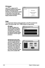
... to display the information on the right panel. This browser provides information on the PCI devices installed on the CPU, hard disk drive space, and memory usage. If the CPU has an enabled Hyper‑Threading, two separate line graphs display the operation of the tab lists all logical drives.
... to display the information on the right panel. This browser provides information on the PCI devices installed on the CPU, hard disk drive space, and memory usage. If the CPU has an enabled Hyper‑Threading, two separate line graphs display the operation of the tab lists all logical drives.


