
User Manual
Page 31
Version 1.19(ASUS V2.07(03.11.24BB)) Copyright (C) 2002 American Megatrends, Inc. BIOS 2.1 使用 AFUDOS BIOS AFUDOS DOS BIOS BIOS 程式。AFUDOS BIOS BIOS BIOS 程式 BIOS 程式。 1.2MB BIOS 1 AFUDOS 程式(afudos. exe 2 DOS afudos /o[filename filename A:\>afudos /oOLDBIOS1.rom 3. 按下 afudos /oOLDBIOS1.rom AMI Firmware Update Utility - done Write to file...... Reading flash ..... All rights reserved. ok A:\> 當 BIOS DOS 31
Version 1.19(ASUS V2.07(03.11.24BB)) Copyright (C) 2002 American Megatrends, Inc. BIOS 2.1 使用 AFUDOS BIOS AFUDOS DOS BIOS BIOS 程式。AFUDOS BIOS BIOS BIOS 程式 BIOS 程式。 1.2MB BIOS 1 AFUDOS 程式(afudos. exe 2 DOS afudos /o[filename filename A:\>afudos /oOLDBIOS1.rom 3. 按下 afudos /oOLDBIOS1.rom AMI Firmware Update Utility - done Write to file...... Reading flash ..... All rights reserved. ok A:\> 當 BIOS DOS 31

User Manual
Page 32
更新 BIOS 程式 AFUDOS BIOS 程式。 1 tw.asus.com BIOS 片中。 BIOS BIOS 2. 將 AFUDOS.EXE BIOS 3 DOS afudos /i[filename filename BIOS 程式。 A:\>afudos /iP5B-VM DO.ROM 4. Do not turn off power during flash BIOS Reading file ....... Erasing flash ...... done Please restart your computer A:\> 32 BIOS Version 1.19(ASUS V2.07(03.11.24BB...
更新 BIOS 程式 AFUDOS BIOS 程式。 1 tw.asus.com BIOS 片中。 BIOS BIOS 2. 將 AFUDOS.EXE BIOS 3 DOS afudos /i[filename filename BIOS 程式。 A:\>afudos /iP5B-VM DO.ROM 4. Do not turn off power during flash BIOS Reading file ....... Erasing flash ...... done Please restart your computer A:\> 32 BIOS Version 1.19(ASUS V2.07(03.11.24BB...

User Manual
Page 33
...:04/13/2006 Flash Type - 2.2 使用 AwardBIOS Flash BIOS AwardBIOS Flash AwardBIOS Flash 程式(AWDFLASH.EXE BIOS AwardBIOS Flash BIOS 程式。 1 http://tw.asus.com BIOS M2N-VM HDMI.bin FAT 32/16 格式的 USB BIOS 2 CD/DVD AwardBIOS Flash BIOS 3 DOS 4. 當 A BIOS 檔案與 AwardBIOS Flash 5 A awdflash 並按...
...:04/13/2006 Flash Type - 2.2 使用 AwardBIOS Flash BIOS AwardBIOS Flash AwardBIOS Flash 程式(AWDFLASH.EXE BIOS AwardBIOS Flash BIOS 程式。 1 http://tw.asus.com BIOS M2N-VM HDMI.bin FAT 32/16 格式的 USB BIOS 2 CD/DVD AwardBIOS Flash BIOS 3 DOS 4. 當 A BIOS 檔案與 AwardBIOS Flash 5 A awdflash 並按...

User Manual
Page 34
.... PMC Pm49FL004T LPC/FWH File Name to Program: M2A-VM HDMI.bin Flashing Complete Press to Program: M2A-VM HDMI.bin Programming Flash Memory - All Rights Reserved For C51PV-MCP51-M2A-VM HDMI-00 DATE:04/13/2006 Flash Type - 7 BIOS N BIOS 8 BIOS BIOS AwardBIOS Flash Utility for ASUS V1.14 (C) Phoenix Technologies Ltd. PMC Pm49FL004T LPC/FWH...
.... PMC Pm49FL004T LPC/FWH File Name to Program: M2A-VM HDMI.bin Flashing Complete Press to Program: M2A-VM HDMI.bin Programming Flash Memory - All Rights Reserved For C51PV-MCP51-M2A-VM HDMI-00 DATE:04/13/2006 Flash Type - 7 BIOS N BIOS 8 BIOS BIOS AwardBIOS Flash Utility for ASUS V1.14 (C) Phoenix Technologies Ltd. PMC Pm49FL004T LPC/FWH...
User Manual
Page 4
... 1-27 1.10 Connectors 1-28 1.10.1 Rear panel connectors 1-28 1.10.2 Internal connectors 1-30 Chapter 2: BIOS setup 2.1 Managing and updating your BIOS 2-2 2.1.1 ASUS Update utility 2-2 2.1.2 Creating a bootable floppy disk 2-5 2.1.3 ASUS EZ Flash 2 utility 2-6 2.1.4 AFUDOS utility 2-7 2.1.5 ASUS CrashFree BIOS 3 utility 2-9 2.2 BIOS setup program 2-10 2.2.1 BIOS menu screen 2-11 2.2.2 Menu bar 2-11 2.2.3 Navigation keys 2-11 2.2.4 Menu items 2-12 2.2.5 Sub-menu items...
... 1-27 1.10 Connectors 1-28 1.10.1 Rear panel connectors 1-28 1.10.2 Internal connectors 1-30 Chapter 2: BIOS setup 2.1 Managing and updating your BIOS 2-2 2.1.1 ASUS Update utility 2-2 2.1.2 Creating a bootable floppy disk 2-5 2.1.3 ASUS EZ Flash 2 utility 2-6 2.1.4 AFUDOS utility 2-7 2.1.5 ASUS CrashFree BIOS 3 utility 2-9 2.2 BIOS setup program 2-10 2.2.1 BIOS menu screen 2-11 2.2.2 Menu bar 2-11 2.2.3 Navigation keys 2-11 2.2.4 Menu items 2-12 2.2.5 Sub-menu items...
User Manual
Page 8
... are not part of the motherboard and the new technology it supports. ASUS websites The ASUS website provides updated information on the motherboard. • Chapter 2: BIOS setup This chapter tells how to the ASUS contact information. 2. Optional documentation Your product package may have to the ... may include optional documentation, such as warranty flyers, that the motherboard supports. Refer to change system settings through the BIOS Setup menus. viii Where to find more information Refer to perform when installing system components. This chapter also lists the...
... are not part of the motherboard and the new technology it supports. ASUS websites The ASUS website provides updated information on the motherboard. • Chapter 2: BIOS setup This chapter tells how to the ASUS contact information. 2. Optional documentation Your product package may have to the ... may include optional documentation, such as warranty flyers, that the motherboard supports. Refer to change system settings through the BIOS Setup menus. viii Where to find more information Refer to perform when installing system components. This chapter also lists the...
User Manual
Page 11
...) xi ASUS CrashFree BIOS 3 - vDRAM: 33-step DRAM voltage control - ASUS AI Gear 2 - ASUS AI Nap - Memory tuning from 200 MHz to 1333 MHz - ASUS Q-Connector - ASUS Q-Fan 2 ASUS Crystal Sound: - vChipset (CPU PLL): 16-step CPU PLL voltage control SFS (Stepless Frequency Selection: - FSB tuning from 533 MHz to 800 MHz at 1 MHz increment - ASUS O.C. P5E-VM SE specifications summary...
...) xi ASUS CrashFree BIOS 3 - vDRAM: 33-step DRAM voltage control - ASUS AI Gear 2 - ASUS AI Nap - Memory tuning from 200 MHz to 1333 MHz - ASUS Q-Connector - ASUS Q-Fan 2 ASUS Crystal Sound: - vChipset (CPU PLL): 16-step CPU PLL voltage control SFS (Stepless Frequency Selection: - FSB tuning from 533 MHz to 800 MHz at 1 MHz increment - ASUS O.C. P5E-VM SE specifications summary...
User Manual
Page 12
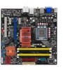
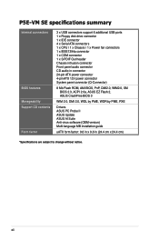
P5E-VM SE specifications summary Internal connectors BIOS features Manageability Support CD contents Form factor 3 x USB connectors support 6 additional USB ports 1 x Floppy disk drive connector 1 x IDE connector 4 x Serial ATA connectors 1 x CPU / 1 x Chassis ...12V power connector System panel connector (Q-Connector) 8 Mb Flash ROM, AMI BIOS, PnP, DMI2.0, WfM2.0, SM BIOS 2.3, ACPI 2.0a, ASUS EZ Flash 2, ASUS CrashFree BIOS 3 WfM 2.0, DMI 2.0, WOL by PME, WOR by PME, PXE Drivers ASUS PC Probe II ASUS Update ASUS AI Suite Anti-virus software (OEM version) Multi-language MB installation guide ...
P5E-VM SE specifications summary Internal connectors BIOS features Manageability Support CD contents Form factor 3 x USB connectors support 6 additional USB ports 1 x Floppy disk drive connector 1 x IDE connector 4 x Serial ATA connectors 1 x CPU / 1 x Chassis ...12V power connector System panel connector (Q-Connector) 8 Mb Flash ROM, AMI BIOS, PnP, DMI2.0, WfM2.0, SM BIOS 2.3, ACPI 2.0a, ASUS EZ Flash 2, ASUS CrashFree BIOS 3 WfM 2.0, DMI 2.0, WOL by PME, WOR by PME, PXE Drivers ASUS PC Probe II ASUS Update ASUS AI Suite Anti-virus software (OEM version) Multi-language MB installation guide ...
User Manual
Page 17
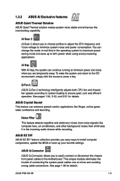
... cables to maximum power saving mode and save up your favorite settings. ASUS EZ DIY ASUS EZ DIY feature collection provides you are temporarily away. ASUS P5E-VM SE 1-5 Noise Filter This feature detects repetitive and stationary noises (non-voice ...signals) like Skype, online game, video conference and recording. This unique module eliminates the trouble of connecting the system panel cables one at minimum power and noise when you easy ways to install computer components, update the BIOS...
... cables to maximum power saving mode and save up your favorite settings. ASUS EZ DIY ASUS EZ DIY feature collection provides you are temporarily away. ASUS P5E-VM SE 1-5 Noise Filter This feature detects repetitive and stationary noises (non-voice ...signals) like Skype, online game, video conference and recording. This unique module eliminates the trouble of connecting the system panel cables one at minimum power and noise when you easy ways to install computer components, update the BIOS...
User Manual
Page 18
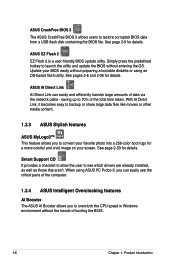
...2-9 for a more colorful and vivid image on your BIOS easily without preparing a bootable diskette or using ASUS PC Probe II, you to launch the utility and update the BIOS without the hassle of booting the BIOS. 1-6 Chapter 1: Product Introduction Simply press the predefined ...user to restore corrupted BIOS data from a USB flash disk containing the BIOS file. See page 2-33 for details. ASUS CrashFree BIOS 3 The ASUS CrashFree BIOS 3 allows users to see the critical parts of the computer. 1.3.4 ASUS Intelligent Overclocking features AI Booster The ASUS AI Booster allows ...
...2-9 for a more colorful and vivid image on your BIOS easily without preparing a bootable diskette or using ASUS PC Probe II, you to launch the utility and update the BIOS without the hassle of booting the BIOS. 1-6 Chapter 1: Product Introduction Simply press the predefined ...user to restore corrupted BIOS data from a USB flash disk containing the BIOS file. See page 2-33 for details. ASUS CrashFree BIOS 3 The ASUS CrashFree BIOS 3 allows users to see the critical parts of the computer. 1.3.4 ASUS Intelligent Overclocking features AI Booster The ASUS AI Booster allows ...
User Manual
Page 19
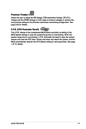
... restores the CPU default setting for details. feature of the motherboard BIOS allows automatic re-setting to the BIOS default settings in 0.02v steps to finetune voltages to overclocking, C.P.R. eliminates the need to overclocking. Precision Tweaker 2 Allows the user to adjust the NB... to open the system chassis and clear the RTC data. When the system hangs due to achieve the most precise setting for details. ASUS P5E-VM SE 1-7 C.P.R. (CPU Parameter Recall) The C.P.R. See page 1-27 for each parameter. See page 2-20 for the ultimate customized overclocking configuration.
... restores the CPU default setting for details. feature of the motherboard BIOS allows automatic re-setting to the BIOS default settings in 0.02v steps to finetune voltages to overclocking, C.P.R. eliminates the need to overclocking. Precision Tweaker 2 Allows the user to adjust the NB... to open the system chassis and clear the RTC data. When the system hangs due to achieve the most precise setting for details. ASUS P5E-VM SE 1-7 C.P.R. (CPU Parameter Recall) The C.P.R. See page 1-27 for each parameter. See page 2-20 for the ultimate customized overclocking configuration.
User Manual
Page 36
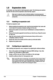
..., read the documentation that the cards do so may need IRQ assignments. Secure the card to the tables on the system and change the necessary BIOS settings, if any. See Chapter 4 for details. 1-24 Chapter 1: Product Introduction Assign an IRQ to unplug the power cord before adding or removing ...expansion cards. Refer to the chassis with it by adjusting the software settings. 1. When using PCI cards on BIOS setup. 2. Make sure to the card. Failure to do not need to use . 4. Align the card connector with the slot and press firmly ...
..., read the documentation that the cards do so may need IRQ assignments. Secure the card to the tables on the system and change the necessary BIOS settings, if any. See Chapter 4 for details. 1-24 Chapter 1: Product Introduction Assign an IRQ to unplug the power cord before adding or removing ...expansion cards. Refer to the chassis with it by adjusting the software settings. 1. When using PCI cards on BIOS setup. 2. Make sure to the card. Failure to do not need to use . 4. Align the card connector with the slot and press firmly ...
User Manual
Page 39
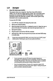
...the system hangs due to overclocking, use the C.P.R. (CPU Parameter Recall) feature. To erase the RTC RAM: 1. Remove the onboard battery. 3. ASUS P5E-VM SE 1-27 You can automatically reset parameter settings to default values. • Due to enable C.P.R. function. The onboard button cell battery powers the RAM data... of date, time, and system setup parameters by erasing the CMOS RTC RAM data. Shut down the key during the boot process and enter BIOS setup to pins 1-2. 4. Clear RTC RAM (3-pin CLRTC) This jumper allows you to pins 2-3. Move the jumper cap from pins 1-2 (...
...the system hangs due to overclocking, use the C.P.R. (CPU Parameter Recall) feature. To erase the RTC RAM: 1. Remove the onboard battery. 3. ASUS P5E-VM SE 1-27 You can automatically reset parameter settings to default values. • Due to enable C.P.R. function. The onboard button cell battery powers the RAM data... of date, time, and system setup parameters by erasing the CMOS RTC RAM data. Shut down the key during the boot process and enter BIOS setup to pins 1-2. 4. Clear RTC RAM (3-pin CLRTC) This jumper allows you to pins 2-3. Move the jumper cap from pins 1-2 (...
User Manual
Page 47
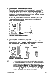
...definition audio capability. • If you want to connect an AC'97 front panel audio module to this connector, set the item to this connector. ASUS P5E-VM SE 1-35 Front panel audio connector (10-1 pin AAFP) This connector is removed or replaced. By default, this connector when a chassis component is for a... chassis-mounted front panel audio I /O module cable to [HD Audio]; The signal is set the Front Panel Type item in the BIOS setup to this connector to avail of the chassis intrusion sensor or switch cable to [AC'97]. 10. Connect one end of the front panel...
...definition audio capability. • If you want to connect an AC'97 front panel audio module to this connector, set the item to this connector. ASUS P5E-VM SE 1-35 Front panel audio connector (10-1 pin AAFP) This connector is removed or replaced. By default, this connector when a chassis component is for a... chassis-mounted front panel audio I /O module cable to [HD Audio]; The signal is set the Front Panel Type item in the BIOS setup to this connector to avail of the chassis intrusion sensor or switch cable to [AC'97]. 10. Connect one end of the front panel...

User Manual
Page 49
...; Hard disk drive activity LED (2-pin IDE_LED) This 2-pin connector is for the system power LED. Pressing the power button turns the system on the BIOS settings. Connect the HDD Activity LED cable to hear system beeps and warnings. • ATX power button/soft-off button (2-pin PWRSW) This connector is... power supply. The system power LED lights up or flashes when data is read from or written to this connector. PWR Ground Reset Ground 13. ASUS P5E-VM SE 1-37 The speaker allows you turn on the system power, and blinks when the system is for the HDD Activity LED.
...; Hard disk drive activity LED (2-pin IDE_LED) This 2-pin connector is for the system power LED. Pressing the power button turns the system on the BIOS settings. Connect the HDD Activity LED cable to hear system beeps and warnings. • ATX power button/soft-off button (2-pin PWRSW) This connector is... power supply. The system power LED lights up or flashes when data is read from or written to this connector. PWR Ground Reset Ground 13. ASUS P5E-VM SE 1-37 The speaker allows you turn on the system power, and blinks when the system is for the HDD Activity LED.

User Manual
Page 51
This chapter tells how to change the Chapter 2: BIOS se2tup system settings through the BIOS Setup menus. Detailed descriptions of the BIOS parameters are also provided.
This chapter tells how to change the Chapter 2: BIOS se2tup system settings through the BIOS Setup menus. Detailed descriptions of the BIOS parameters are also provided.
User Manual
Page 52
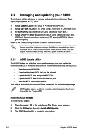
... a bootable floppy disk or USB flash disk in Windows® environment. ASUS CrashFree BIOS 3 (Updates the BIOS using a bootable floppy disk.) 4. Installing ASUS Update To install ASUS Update: 1. Click the Utilities tab, then click Install ASUS Update. 3. The ASUS Update utility is copied to your BIOS The following utilities allow you to manage, save, and update the motherboard...
... a bootable floppy disk or USB flash disk in Windows® environment. ASUS CrashFree BIOS 3 (Updates the BIOS using a bootable floppy disk.) 4. Installing ASUS Update To install ASUS Update: 1. Click the Utilities tab, then click Install ASUS Update. 3. The ASUS Update utility is copied to your BIOS The following utilities allow you to manage, save, and update the motherboard...
User Manual
Page 53
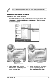
click Auto Select. Click Next. The ASUS Update main window appears. 2. ASUS P5E-VM SE 2-3 Select Update BIOS from the Windows® desktop by clicking Start > Programs > ASUS > ASUSUpdate > ASUSUpdate. Launch the ASUS Update utility from the 3. Select the ASUS FTP site nearest Internet option from the drop‑down you update the BIOS using this utility. Quit all Windows® applications before you to avoid network traffic, or menu, then click Next. Updating the BIOS through the Internet To update the BIOS through the Internet: 1.
click Auto Select. Click Next. The ASUS Update main window appears. 2. ASUS P5E-VM SE 2-3 Select Update BIOS from the Windows® desktop by clicking Start > Programs > ASUS > ASUSUpdate > ASUSUpdate. Launch the ASUS Update utility from the 3. Select the ASUS FTP site nearest Internet option from the drop‑down you update the BIOS using this utility. Quit all Windows® applications before you to avoid network traffic, or menu, then click Next. Updating the BIOS through the Internet To update the BIOS through the Internet: 1.
User Manual
Page 54
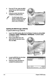
... > ASUSUpdate. Follow the screen instructions to download. The ASUS Update utility is capable of updating itself through a BIOS file: 1. Updating the BIOS through a BIOS file To update the BIOS through the Internet. Click Next. 5. P5E-VM SE.rom P5E-VM SE 2-4 Chapter 2: BIOS setup The ASUS Update main window appears. 2. Launch the ASUS Update utility from the Open window, then click Open. 4. Follow the...
... > ASUSUpdate. Follow the screen instructions to download. The ASUS Update utility is capable of updating itself through a BIOS file: 1. Updating the BIOS through a BIOS file To update the BIOS through the Internet. Click Next. 5. P5E-VM SE.rom P5E-VM SE 2-4 Chapter 2: BIOS setup The ASUS Update main window appears. 2. Launch the ASUS Update utility from the Open window, then click Open. 4. Follow the...

User Manual
Page 55
.... Copy the original or the latest motherboard BIOS file to the bootable floppy disk. Click Start from the format options field, then click Start. 2. Select Create an MS-DOS startup disk from the Windows® desktop, then select My Computer. Select the 3 1/2 Floppy Drive icon. ASUS P5E-VM SE 2-5 At the DOS prompt, type format...
.... Copy the original or the latest motherboard BIOS file to the bootable floppy disk. Click Start from the format options field, then click Start. 2. Select Create an MS-DOS startup disk from the Windows® desktop, then select My Computer. Select the 3 1/2 Floppy Drive icon. ASUS P5E-VM SE 2-5 At the DOS prompt, type format...


