
P5A User Manual
Page 1
R P5A Pentium® Super7 Motherboard USER'S MANUAL
R P5A Pentium® Super7 Motherboard USER'S MANUAL
P5A User Manual
Page 2
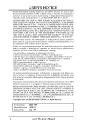
...any form or by any of the means indicated on the product itself. Product Name: ASUS P5A Manual Revision: 1.07 E382 Release Date: May 1999 2 ASUS P5A User's Manual USER'S NOTICE No part of this manual may or may be extended if: (1) the product is repaired, modified or altered, ...unless such repair, modification of alteration is authorized in writing by ASUS; Manual revisions are released for each product design...
...any form or by any of the means indicated on the product itself. Product Name: ASUS P5A Manual Revision: 1.07 E382 Release Date: May 1999 2 ASUS P5A User's Manual USER'S NOTICE No part of this manual may or may be extended if: (1) the product is repaired, modified or altered, ...unless such repair, modification of alteration is authorized in writing by ASUS; Manual revisions are released for each product design...

P5A User Manual
Page 3
...-2-2894-3447 ext. 111 Fax: +886-2-2895-9254 Email: tsd@asus.com.tw Newsgroup: news2.asus.com.tw WWW: www.asus.com.tw FTP: ftp.asus.com.tw/pub/ASUS ASUS COMPUTER INTERNATIONAL (America) Marketing Address: 6737 Mowry Avenue, Mowry Business ...ASUS ASUS COMPUTER GmbH (Europe) Marketing Address: Harkort Str. 25, 40880 Ratingen, BRD, Germany Telephone: 49-2102-445011 Fax: 49-2102-442066 Email: [email protected] Technical Support Hotline: 49-2102-499712 BBS: 49-2102-448690 Email: [email protected] WWW: www.asuscom.de FTP: ftp.asuscom.de/pub/ASUSCOM ASUS P5A User's Manual...
...-2-2894-3447 ext. 111 Fax: +886-2-2895-9254 Email: tsd@asus.com.tw Newsgroup: news2.asus.com.tw WWW: www.asus.com.tw FTP: ftp.asus.com.tw/pub/ASUS ASUS COMPUTER INTERNATIONAL (America) Marketing Address: 6737 Mowry Avenue, Mowry Business ...ASUS ASUS COMPUTER GmbH (Europe) Marketing Address: Harkort Str. 25, 40880 Ratingen, BRD, Germany Telephone: 49-2102-445011 Fax: 49-2102-442066 Email: [email protected] Technical Support Hotline: 49-2102-499712 BBS: 49-2102-448690 Email: [email protected] WWW: www.asuscom.de FTP: ftp.asuscom.de/pub/ASUSCOM ASUS P5A User's Manual...

P5A User Manual
Page 4
... Chipset Features Setup 45 Details of Chipset Features Setup 46 Power Management Setup 49 Details of the ASUS P5A Motherboard 11 III. FEATURES 8 ASUS P5A Motherboard 8 Introduction to ASUS Smart Series Motherboards 9 Parts of Power Management Setup 49 4 ASUS P5A User's Manual Central Processing Unit (CPU 21 4. BIOS SOFTWARE 36 Main Menu 36 Managing and Updating Your Motherboard...
... Chipset Features Setup 45 Details of Chipset Features Setup 46 Power Management Setup 49 Details of the ASUS P5A Motherboard 11 III. FEATURES 8 ASUS P5A Motherboard 8 Introduction to ASUS Smart Series Motherboards 9 Parts of Power Management Setup 49 4 ASUS P5A User's Manual Central Processing Unit (CPU 21 4. BIOS SOFTWARE 36 Main Menu 36 Managing and Updating Your Motherboard...

P5A User Manual
Page 5
... Auto Detection 56 Save & Exit Setup 57 Exit Without Saving 57 V. ASUS LAN Card 65 ASUS PCI-L101 Fast Ethernet Card 65 Features 66 Software Driver Support 66 Question and Answer 66 APPENDIX 67 Glossary 67 ASUS P5A User's Manual 5 SUPPORT SOFTWARE 59 ASUS Smart Motherboard Support CD 59 Desktop Management Interface (DMI 60 Introducing the...
... Auto Detection 56 Save & Exit Setup 57 Exit Without Saving 57 V. ASUS LAN Card 65 ASUS PCI-L101 Fast Ethernet Card 65 Features 66 Software Driver Support 66 Question and Answer 66 APPENDIX 67 Glossary 67 ASUS P5A User's Manual 5 SUPPORT SOFTWARE 59 ASUS Smart Motherboard Support CD 59 Desktop Management Interface (DMI 60 Introducing the...

P5A User Manual
Page 6
...; This device may cause undesired operation. WARNING! Cet appareil numérique de la classe B est conforme à la norme NMB-003 du Canada. 6 ASUS P5A User's Manual However, there is connected. • Consult the dealer or an experienced radio/TV technician for help. This equipment generates, uses and can be determined by...
...; This device may cause undesired operation. WARNING! Cet appareil numérique de la classe B est conforme à la norme NMB-003 du Canada. 6 ASUS P5A User's Manual However, there is connected. • Consult the dealer or an experienced radio/TV technician for help. This equipment generates, uses and can be determined by...

P5A User Manual
Page 7
INTRODUCTION Sections/Checklist I . Introduction Manual information and checklist II. ASUS CIDB Installation of spare jumpers (1) Support CD with drivers and utilities (1) User's Manual ASUS CIDB chassis sensor module (optional) ASUS IrDA-compliant infrared module (optional) ASUS PCI-L101 Wake-On-LAN 10/100 Ethernet Card (optional) ASUS P5A User's Manual 7 Features Information and specifications concerning this Manual is complete. BIOS Software...
INTRODUCTION Sections/Checklist I . Introduction Manual information and checklist II. ASUS CIDB Installation of spare jumpers (1) Support CD with drivers and utilities (1) User's Manual ASUS CIDB chassis sensor module (optional) ASUS IrDA-compliant infrared module (optional) ASUS PCI-L101 Wake-On-LAN 10/100 Ethernet Card (optional) ASUS P5A User's Manual 7 Features Information and specifications concerning this Manual is complete. BIOS Software...

P5A User Manual
Page 8
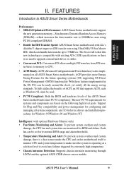
FEATURES ASUS P5A Motherboard • ALi AGPset: ALi® (Acer Laboratories Inc.) Aladdin V... Provides two high-speed UART compatible serial ports and one parallel port with special network cards, such as the ASUS PCI-L101 10/100 Fast Ethernet PCI card. • PC Health Monitoring (optional): Provides a convenient utility ...See section V) • USB, PS/2 Mouse, IrDA Connector: Supports an optional cable and bracket set . 8 ASUS P5A User's Manual UART2 can also be directed from COM2 to the Infrared Module for high performance, component level interconnection targeted at 3D graphical...
FEATURES ASUS P5A Motherboard • ALi AGPset: ALi® (Acer Laboratories Inc.) Aladdin V... Provides two high-speed UART compatible serial ports and one parallel port with special network cards, such as the ASUS PCI-L101 10/100 Fast Ethernet PCI card. • PC Health Monitoring (optional): Provides a convenient utility ...See section V) • USB, PS/2 Mouse, IrDA Connector: Supports an optional cable and bracket set . 8 ASUS P5A User's Manual UART2 can also be directed from COM2 to the Infrared Module for high performance, component level interconnection targeted at 3D graphical...
P5A User Manual
Page 9
... avoid any failures triggered by extremely high temperature. • Chassis intrusion Detection: Supports chassis-intrusion monitoring through LDCM and the optional ASUS CIDB chassis sensor module. ACPI provides more Energy Saving Features for its normal RPM range and alarm thresholds. • Temperature Monitoring ... under the CPU and on all system components, and 32-bit device drivers and installation procedures for RPM and failure. ASUS P5A User's Manual 9 The best of the ASUS Smart Series motherboards meet PC'98 compliancy. II. Each fan can be used. • PC'98 Compliant: Both ...
... avoid any failures triggered by extremely high temperature. • Chassis intrusion Detection: Supports chassis-intrusion monitoring through LDCM and the optional ASUS CIDB chassis sensor module. ACPI provides more Energy Saving Features for its normal RPM range and alarm thresholds. • Temperature Monitoring ... under the CPU and on all system components, and 32-bit device drivers and installation procedures for RPM and failure. ASUS P5A User's Manual 9 The best of the ASUS Smart Series motherboards meet PC'98 compliancy. II. Each fan can be used. • PC'98 Compliant: Both ...

P5A User Manual
Page 10
... for future processors, so monitoring is in sleep mode. FEATURES • Voltage Monitoring and Alert: System voltage levels are used up to the user. 10 ASUS P5A User's Manual FEA TURES Smart Series II.
... for future processors, so monitoring is in sleep mode. FEATURES • Voltage Monitoring and Alert: System voltage levels are used up to the user. 10 ASUS P5A User's Manual FEA TURES Smart Series II.

P5A User Manual
Page 11
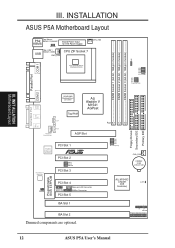
FEA TURES Motherboard Parts II. FEATURES Parts of the ASUS P5A Motherboard PS/2 Mouse (top) and Keyboard USB Port ATX Power CPU ZIF ALi Aladdin V Socket 7 AGPset 3 DIMM Sockets Serial and Parallel Connectors 512KB/1MB Pipelined Burst L2 Cache Game/MIDI Port (optional) Accelerated Graphics Port ESS Audio (optional) 5 PCI Slots Health Monitoring Chip (optional) 2 ISA Slots ASUS P5A User's Manual 11 II.
FEA TURES Motherboard Parts II. FEATURES Parts of the ASUS P5A Motherboard PS/2 Mouse (top) and Keyboard USB Port ATX Power CPU ZIF ALi Aladdin V Socket 7 AGPset 3 DIMM Sockets Serial and Parallel Connectors 512KB/1MB Pipelined Burst L2 Cache Game/MIDI Port (optional) Accelerated Graphics Port ESS Audio (optional) 5 PCI Slots Health Monitoring Chip (optional) 2 ISA Slots ASUS P5A User's Manual 11 II.
P5A User Manual
Page 12
... Primary IDE FS0 FS1 FS2 FS3 BUS Frequency CHA_FAN CR2032 3 Volt Lithium Cell ALi M1543C Chipset (IDE Controller) CLRTC IR + IDELED Panel Connections 12 ASUS P5A User's Manual INSTALLATION ASUS P5A Motherboard Layout PS2 Top: Mouse Bottom: Keyboard KBMS KBPWR Board Power Input for ATX Power Supply USB Top: USB 1 Bottom: USB 2 PWR_FAN CPU ZIF...
... Primary IDE FS0 FS1 FS2 FS3 BUS Frequency CHA_FAN CR2032 3 Volt Lithium Cell ALi M1543C Chipset (IDE Controller) CLRTC IR + IDELED Panel Connections 12 ASUS P5A User's Manual INSTALLATION ASUS P5A Motherboard Layout PS2 Top: Mouse Bottom: Keyboard KBMS KBPWR Board Power Input for ATX Power Supply USB Top: USB 1 Bottom: USB 2 PWR_FAN CPU ZIF...
P5A User Manual
Page 13
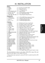
... use this address or else conflicts will occur. **If the onboard audio (optional) is selected, PCI Slot 5 can only be used for a PCI slave device. ASUS P5A User's Manual 13 INST ALLATION Contents III. III.
... use this address or else conflicts will occur. **If the onboard audio (optional) is selected, PCI Slot 5 can only be used for a PCI slave device. ASUS P5A User's Manual 13 INST ALLATION Contents III. III.

P5A User Manual
Page 14
...supply case. 3. To protect them against damage from the system. Hold components by the onboard button cell battery. R III. INST ALLATION Jumpers P5A Clear RTC RAM CLRTC Short solder points to touch the IC chips, leads or connectors, or other components. 4. III. Unplug your computer. ...user preferences. Real Time Clock (RTC) RAM (CLRTC) The CMOS RAM is powered by the edges and try not to Clear CMOS 14 ASUS P5A User's Manual Install System Memory Modules 3. Place components on a grounded antistatic pad or on the Motherboard 2. Install the Central Processing Unit (CPU) 4. ...
...supply case. 3. To protect them against damage from the system. Hold components by the onboard button cell battery. R III. INST ALLATION Jumpers P5A Clear RTC RAM CLRTC Short solder points to touch the IC chips, leads or connectors, or other components. 4. III. Unplug your computer. ...user preferences. Real Time Clock (RTC) RAM (CLRTC) The CMOS RAM is powered by the edges and try not to Clear CMOS 14 ASUS P5A User's Manual Install System Memory Modules 3. Place components on a grounded antistatic pad or on the Motherboard 2. Install the Central Processing Unit (CPU) 4. ...

P5A User Manual
Page 15
... This feature requires an ATX power supply that can use your computer components' life. P5A Voltage Input/Output Selection 123 VIO1 3.5Volts (DEFAULT) 123 3.6Volts 4. SOLOID SREQ SGNT SOLOID SREQ SGNT P5A Audio Setting 1 2 3 Enabled (DEFAULT) 1 2 3 Disabled ASUS P5A User's Manual 15 III. WARNING! Keyboard Power Up (KBPWR) This allows you can supply at least...
... This feature requires an ATX power supply that can use your computer components' life. P5A Voltage Input/Output Selection 123 VIO1 3.5Volts (DEFAULT) 123 3.6Volts 4. SOLOID SREQ SGNT SOLOID SREQ SGNT P5A Audio Setting 1 2 3 Enabled (DEFAULT) 1 2 3 Disabled ASUS P5A User's Manual 15 III. WARNING! Keyboard Power Up (KBPWR) This allows you can supply at least...

P5A User Manual
Page 16
...frequency to send to BUS Frequency Multiple (BF0, BF1, BF2) These jumpers set in conjunction with your CPU when possible. 16 ASUS P5A User's Manual Frequencies above 100MHz exceed the specifications for the onboard chipset and are not guaranteed to the instructions included with the jumpers for general reference... 77.6MHz 38.3MHz 120MHz 80MHz 40MHz CPU External Clock (BUS) Frequency Selection BF2 BF1 BF0 BF2 BF1 BF0 BF2 BF1 BF0 BF2 BF1 BF0 P5A Match the Mult. (Multiple) column of the CPU's External frequency (or BUS Clock). CPU E → - Always refer to be set...
...frequency to send to BUS Frequency Multiple (BF0, BF1, BF2) These jumpers set in conjunction with your CPU when possible. 16 ASUS P5A User's Manual Frequencies above 100MHz exceed the specifications for the onboard chipset and are not guaranteed to the instructions included with the jumpers for general reference... 77.6MHz 38.3MHz 120MHz 80MHz 40MHz CPU External Clock (BUS) Frequency Selection BF2 BF1 BF0 BF2 BF1 BF0 BF2 BF1 BF0 BF2 BF1 BF0 P5A Match the Mult. (Multiple) column of the CPU's External frequency (or BUS Clock). CPU E → - Always refer to be set...

P5A User Manual
Page 17
ASUS P5A User's Manual 17 III. Mult.) Mult. FS3 FS2 FS1 FS0 BF0 BF1 BF2 AMD-K6-III/450 AMD-K6-III/400 450MHz A-4.5x 100MHz [2-3] [1-2] [1-2] [1-2] [2-3] [2-3] [2-3] 400MHz A-4.0x 100MHz [2-3] [1-2] ... [2-3] [1-2] [----] IDT WinChip 2™ 240MHz F-4.0x 60MHz [2-3] [2-3] [2-3] [2-3] [2-3] [1-2] [2-3] *The only IBM or Cyrix 6x86(L) (or M I) that is supported on this motherboard is revision 2.7 or later (see ASUS CONTACT INFORMATION for URLs). INST ALLATION Jumpers III. INSTALLATION Set the jumpers by the Internal speed of your CPU as follows: CPU Model Freq. (BUS...
ASUS P5A User's Manual 17 III. Mult.) Mult. FS3 FS2 FS1 FS0 BF0 BF1 BF2 AMD-K6-III/450 AMD-K6-III/400 450MHz A-4.5x 100MHz [2-3] [1-2] [1-2] [1-2] [2-3] [2-3] [2-3] 400MHz A-4.0x 100MHz [2-3] [1-2] ... [2-3] [1-2] [----] IDT WinChip 2™ 240MHz F-4.0x 60MHz [2-3] [2-3] [2-3] [2-3] [2-3] [1-2] [2-3] *The only IBM or Cyrix 6x86(L) (or M I) that is supported on this motherboard is revision 2.7 or later (see ASUS CONTACT INFORMATION for URLs). INST ALLATION Jumpers III. INSTALLATION Set the jumpers by the Internal speed of your CPU as follows: CPU Model Freq. (BUS...

P5A User Manual
Page 18
... Core Voltage Selection 1 2 3 2.0Volts 2.1Volts 1 2 3 2.5Volts 2.6Volts 1 2 3 3.0Volts 3.1Volts 1 2 3 3.5Volts 2.2Volts 2.7Volts 3.2Volts 2.3Volts 2.8Volts 3.3Volts 2.4Volts 2.9Volts 3.4Volts 18 ASUS P5A User's Manual Manufacturer CPU Type AMD (.25micron) K6-III/400,450 K6-2/450,475 Single Plane ---- AMD (.35micron) K6-166,200 ---- Look on this motherboard must be ...
... Core Voltage Selection 1 2 3 2.0Volts 2.1Volts 1 2 3 2.5Volts 2.6Volts 1 2 3 3.0Volts 3.1Volts 1 2 3 3.5Volts 2.2Volts 2.7Volts 3.2Volts 2.3Volts 2.8Volts 3.3Volts 2.4Volts 2.9Volts 3.4Volts 18 ASUS P5A User's Manual Manufacturer CPU Type AMD (.25micron) K6-III/400,450 K6-2/450,475 Single Plane ---- AMD (.35micron) K6-166,200 ---- Look on this motherboard must be ...

P5A User Manual
Page 19
...Rows 4&5) SDRAM 8, 16, 32, 64, 128, 256MB x1 Total System Memory (Max 768MB) = NOTES • At the time this User's Manual was written, 256MB DIMMs are available for best performance vs. IMPORTANT (see General DIMM Notes below) • To make the proper settings through SDRAM ... set the CPU bus frequency to form a memory size between 8MB and 768MB. One side (with the current Intel PC100 SDRAM specification.. ASUS P5A User's Manual 19 INSTALLATION 2. System Memory (DIMM) This motherboard uses only Dual Inline Memory Modules (DIMMs). Sockets are either 8, 16, 32, 64...
...Rows 4&5) SDRAM 8, 16, 32, 64, 128, 256MB x1 Total System Memory (Max 768MB) = NOTES • At the time this User's Manual was written, 256MB DIMMs are available for best performance vs. IMPORTANT (see General DIMM Notes below) • To make the proper settings through SDRAM ... set the CPU bus frequency to form a memory size between 8MB and 768MB. One side (with the current Intel PC100 SDRAM specification.. ASUS P5A User's Manual 19 INSTALLATION 2. System Memory (DIMM) This motherboard uses only Dual Inline Memory Modules (DIMMs). Sockets are either 8, 16, 32, 64...

P5A User Manual
Page 20
INST ALLATION System Memory 88 Pins 60 Pins 20 Pins Lock P5A 168 Pin DIMM Memory Sockets The DIMMs must tell your retailer the correct DIMM type before purchasing. R III. SDRAM DIMMs have different pin contacts on ...) DRAM Key Position RFU Unbuffered Buffered Voltage Key Position 5.0V Reserved 3.3V The notches on the motherboard. This motherboard supports four clock signals. 20 ASUS P5A User's Manual INSTALLATION DIMM Memory Installation Procedures: Insert the module(s) as shown. Because the number of pins are different on either side of the breaks, the module...
INST ALLATION System Memory 88 Pins 60 Pins 20 Pins Lock P5A 168 Pin DIMM Memory Sockets The DIMMs must tell your retailer the correct DIMM type before purchasing. R III. SDRAM DIMMs have different pin contacts on ...) DRAM Key Position RFU Unbuffered Buffered Voltage Key Position 5.0V Reserved 3.3V The notches on the motherboard. This motherboard supports four clock signals. 20 ASUS P5A User's Manual INSTALLATION DIMM Memory Installation Procedures: Insert the module(s) as shown. Because the number of pins are different on either side of the breaks, the module...


