
P5A-B User Manual
Page 4
... ASUS P5A-B User's Manual Central Processing Unit (CPU 21 4. Expansion Cards 23 Expansion Card Installation Procedure 23 Assigning IRQs for Expansion Cards 23 Assigning DMA Channels for ISA Cards 24 ISA Cards and Hardware Monitor 24 Accelerated Graphics Port 24 5. Jumpers 14 Jumper ... 49 Details of Power Management Setup 49 PNP and PCI Setup 52 Details of the ASUS P5A-B Motherboard 11 III. External Connectors 25 Power Connection Procedures 35 IV. INSTALLATION 12 ASUS P5A-B Motherboard Layout 12 Installation Steps 14 1. CONTENTS I. INTRODUCTION 7 How this Manual is...
... ASUS P5A-B User's Manual Central Processing Unit (CPU 21 4. Expansion Cards 23 Expansion Card Installation Procedure 23 Assigning IRQs for Expansion Cards 23 Assigning DMA Channels for ISA Cards 24 ISA Cards and Hardware Monitor 24 Accelerated Graphics Port 24 5. Jumpers 14 Jumper ... 49 Details of Power Management Setup 49 PNP and PCI Setup 52 Details of the ASUS P5A-B Motherboard 11 III. External Connectors 25 Power Connection Procedures 35 IV. INSTALLATION 12 ASUS P5A-B Motherboard Layout 12 Installation Steps 14 1. CONTENTS I. INTRODUCTION 7 How this Manual is...

P5A-B User Manual
Page 7
...) APPENDIX Glossary of spare jumpers (1) CD disc with support drivers and utilities (1) User's Manual Audio Bracket (only available with ISA audio option) ASUS CIDB chassis sensor module (optional) PS/2 Mouse, Infrared, USB1, and USB2 external connector module (optional) ASUS PCI-L101 Wake-On-LAN 10/100 Ethernet Card (optional) ASUS P5A-B User's Manual 7 Features Information...
...) APPENDIX Glossary of spare jumpers (1) CD disc with support drivers and utilities (1) User's Manual Audio Bracket (only available with ISA audio option) ASUS CIDB chassis sensor module (optional) PS/2 Mouse, Infrared, USB1, and USB2 external connector module (optional) ASUS PCI-L101 Wake-On-LAN 10/100 Ethernet Card (optional) ASUS P5A-B User's Manual 7 Features Information...

P5A-B User Manual
Page 13
ASUS P5A-B User's Manual 13 INSTALLATION Jumpers 1) CLRTC p. 15 Real Time Clock (RTC) RAM 2) VIO p. 15 Voltage Input/Output Selection 4) FS0, FS1, FS2, FS3 p. 16 CPU External (BUS) Frequency Selection 5) BF0, BF1, ...
ASUS P5A-B User's Manual 13 INSTALLATION Jumpers 1) CLRTC p. 15 Real Time Clock (RTC) RAM 2) VIO p. 15 Voltage Input/Output Selection 4) FS0, FS1, FS2, FS3 p. 16 CPU External (BUS) Frequency Selection 5) BF0, BF1, ...
P5A-B User Manual
Page 14
... object or to touch the IC chips, leads or connectors, or other components. 4. Install the Central Processing Unit (CPU) 4. INST ALLATION Jumpers 14 ASUS P5A-B User's Manual Computer motherboards, baseboards and components, such as the power supply case. 3. If you do not have one, touch both of...a metal object, such as SCSI cards, contain very delicate Integrated Circuit (IC) chips. Setup the BIOS Software 1. III. Set Jumpers on your computer when working on the bag that came with the component whenever the components are separated from static electricity, you should follow...
... object or to touch the IC chips, leads or connectors, or other components. 4. Install the Central Processing Unit (CPU) 4. INST ALLATION Jumpers 14 ASUS P5A-B User's Manual Computer motherboards, baseboards and components, such as the power supply case. 3. If you do not have one, touch both of...a metal object, such as SCSI cards, contain very delicate Integrated Circuit (IC) chips. Setup the BIOS Software 1. III. Set Jumpers on your computer when working on the bag that came with the component whenever the components are separated from static electricity, you should follow...

P5A-B User Manual
Page 15
... (CLRTC) The CMOS RAM is powered by the onboard button cell battery. ASUS P5A-B User's Manual 15 R 1 2 3 3.5Volts 3.6Volts 3.8Volts (DEFAULT) 4.0Volts P5A-B Voltage Input/Output Selection WARNING! INST ALLATION Jumpers III. VIO0 VIO1 VIO0 VIO1 VIO0 VIO1 VIO0 VIO1 III. R P5A-B Clear RTC RAM CLRTC Short solder points to the DRAM, chipset, and AGP...
... (CLRTC) The CMOS RAM is powered by the onboard button cell battery. ASUS P5A-B User's Manual 15 R 1 2 3 3.5Volts 3.6Volts 3.8Volts (DEFAULT) 4.0Volts P5A-B Voltage Input/Output Selection WARNING! INST ALLATION Jumpers III. VIO0 VIO1 VIO0 VIO1 VIO0 VIO1 VIO0 VIO1 III. R P5A-B Clear RTC RAM CLRTC Short solder points to the DRAM, chipset, and AGP...

P5A-B User Manual
Page 16
...frequency (called the BUS Clock) within the CPU. CPU to BUS Frequency Multiple (BF0, BF1, BF2) These jumpers set in conjunction with your CPU when possible. 16 ASUS P5A-B User's Manual Always refer to these CPU types: CPU A: AMD-K6-III,AMD-K6-2/400&faster CPU ... CPU A → 4.0x(4/1) CPU B → 4.0x(4/1) CPU C → - The table on the opposite page to the instructions included with the jumpers for general reference purposes only. INSTALLATION 3. These must be stable. CPU D → - Frequencies above 100MHz exceed the specifications for the onboard chipset and are ...
...frequency (called the BUS Clock) within the CPU. CPU to BUS Frequency Multiple (BF0, BF1, BF2) These jumpers set in conjunction with your CPU when possible. 16 ASUS P5A-B User's Manual Always refer to these CPU types: CPU A: AMD-K6-III,AMD-K6-2/400&faster CPU ... CPU A → 4.0x(4/1) CPU B → 4.0x(4/1) CPU C → - The table on the opposite page to the instructions included with the jumpers for general reference purposes only. INSTALLATION 3. These must be stable. CPU D → - Frequencies above 100MHz exceed the specifications for the onboard chipset and are ...

P5A-B User Manual
Page 17
... [----] [2-3] [1-2] [2-3] *NOTE:The only IBM or Cyrix 6x86(L) (or M I) that is supported on this motherboard is revision 2.7 or later (see next page). ASUS P5A-B User's Manual 17 A-4.5x 100MHz A-4.0x 100MHz A-5.0x 95MHz A-4.5x 100MHz A-4.0x 100MHz B-4.0x 95MHz B-5.5x 66MHz B-3.5x 100MHz B-3.5x 95MHz B-3.0x 100MHz B-4.0x 66MHz... [2-3] [2-3] [2-3] [2-3] [2-3] [2-3] [2-3] [1-2] [2-3] [2-3] [2-3] [1-2] [2-3] [2-3] [2-3] [2-3] [2-3] [2-3] [2-3] (Freq. INSTALLATION Set the jumpers by the Internal speed of your CPU as follows: CPU Model Freq. AMD-K6-III/450 AMD-K6-III/400 450MHz 400MHz AMD-...
... [----] [2-3] [1-2] [2-3] *NOTE:The only IBM or Cyrix 6x86(L) (or M I) that is supported on this motherboard is revision 2.7 or later (see next page). ASUS P5A-B User's Manual 17 A-4.5x 100MHz A-4.0x 100MHz A-5.0x 95MHz A-4.5x 100MHz A-4.0x 100MHz B-4.0x 95MHz B-5.5x 66MHz B-3.5x 100MHz B-3.5x 95MHz B-3.0x 100MHz B-4.0x 66MHz... [2-3] [2-3] [2-3] [2-3] [2-3] [2-3] [2-3] [1-2] [2-3] [2-3] [2-3] [1-2] [2-3] [2-3] [2-3] [2-3] [2-3] [2-3] [2-3] (Freq. INSTALLATION Set the jumpers by the Internal speed of your CPU as follows: CPU Model Freq. AMD-K6-III/450 AMD-K6-III/400 450MHz 400MHz AMD-...
P5A-B User Manual
Page 18
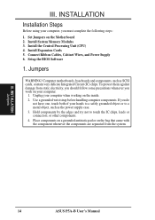
... 2.3Volts 2.8Volts 3.3Volts 2.4Volts 2.9Volts 3.4Volts 18 ASUS P5A-B User's Manual Always refer to be Revision 2.7 or later. Manufacturer CPU Type AMD (.25micron) K6-III/400,450 K6-2/450,475 Single Plane ---- IBM/Cyrix 6x86MX ---- Voltage Regulator Output Selection (VID0, 1, 2, 3) These jumpers set the appropriate VID jumpers according to the CPU. WARNING! INSTALLATION Compatible...
... 2.3Volts 2.8Volts 3.3Volts 2.4Volts 2.9Volts 3.4Volts 18 ASUS P5A-B User's Manual Always refer to be Revision 2.7 or later. Manufacturer CPU Type AMD (.25micron) K6-III/400,450 K6-2/450,475 Single Plane ---- IBM/Cyrix 6x86MX ---- Voltage Regulator Output Selection (VID0, 1, 2, 3) These jumpers set the appropriate VID jumpers according to the CPU. WARNING! INSTALLATION Compatible...
P5A-B User Manual
Page 21
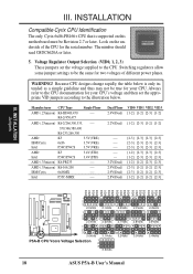
...corner. With the added weight of the lever. IMPORTANT: You must set jumpers for "CPU to prevent overheating. Locate the ZIF socket and open it to BUS Frequency Ratio" and jumpers for reference only; you turn off your system. The CPU that will ...only fit in the one hole is backwards compatible with the motherboard should have a fan attached to a 90-degree right angle. Notice that there is a blank area where one orientation as your guide. Blank Lever Lock R P5A-B ZIF Socket 7 ASUS P5A...
...corner. With the added weight of the lever. IMPORTANT: You must set jumpers for "CPU to prevent overheating. Locate the ZIF socket and open it to BUS Frequency Ratio" and jumpers for reference only; you turn off your system. The CPU that will ...only fit in the one hole is backwards compatible with the motherboard should have a fan attached to a 90-degree right angle. Notice that there is a blank area where one orientation as your guide. Blank Lever Lock R P5A-B ZIF Socket 7 ASUS P5A...

P5A-B User Manual
Page 23
... of ISA cards. Carefully align the card's connectors and press firmly. 6. Secure the card on the slot you configure the card's jumpers manually and then install it in step 4. 7. System IRQs are available to one use the same IRQs or your motherboard and expansion cards...two devices are already in use IRQs. Keep the bracket for your expansion card documentation on the ISA bus. Double clicking on your specific card. 2. ASUS P5A-B User's Manual 23 Replace the computer system's cover. 8. Setup the BIOS if necessary (such as "Legacy" ISA cards, requires that you a...
... of ISA cards. Carefully align the card's connectors and press firmly. 6. Secure the card on the slot you configure the card's jumpers manually and then install it in step 4. 7. System IRQs are available to one use the same IRQs or your motherboard and expansion cards...two devices are already in use IRQs. Keep the bracket for your expansion card documentation on the ISA bus. Double clicking on your specific card. 2. ASUS P5A-B User's Manual 23 Replace the computer system's cover. 8. Setup the BIOS if necessary (such as "Legacy" ISA cards, requires that you a...

P5A-B User Manual
Page 24
INST ALLATION Expansion Cards III. If the system has both legacy and PnP, may also need to the system. P5A-B Accelerated Graphics Port (AGP) 24 ASUS P5A-B User's Manual In the PCI bus design, the BIOS automatically assigns an IRQ to a PCI slot that do not work with the BIOS, you need...ISA cards must first install the AGP Mini Port Driver (see support CD) to avail of the BIOS SOFTWARE, choose Yes in it that the jumpers on this address or else conflicts will occur. DMA assignments for legacy ISA cards (under PNP AND PCI SETUP of the motherboard's AGP features. ...
INST ALLATION Expansion Cards III. If the system has both legacy and PnP, may also need to the system. P5A-B Accelerated Graphics Port (AGP) 24 ASUS P5A-B User's Manual In the PCI bus design, the BIOS automatically assigns an IRQ to a PCI slot that do not work with the BIOS, you need...ISA cards must first install the AGP Mini Port Driver (see support CD) to avail of the BIOS SOFTWARE, choose Yes in it that the jumpers on this address or else conflicts will occur. DMA assignments for legacy ISA cards (under PNP AND PCI SETUP of the motherboard's AGP features. ...
P5A-B User Manual
Page 25
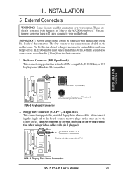
...This motherboard accepts an AT Keyboard Connector Plug as shown here. IMPORTANT: Ribbon cables should always be less than 6in. (15cm) from jumpers in the wrong orientation when using ribbon cables with the second drive connector no more than 18in. (46cm), with pin 5 plugged). ...III. INST ALLATION Connectors III. Placing jumper caps over these will cause damage to your cable to prevent inserting in "Map of the connector. Pin 1 is removed to Pin 1 R R P5A-B Floppy Disk Drive Connector ASUS P5A-B User's Manual 25 Keyboard Connector (KB, 5-pin female) This...
...This motherboard accepts an AT Keyboard Connector Plug as shown here. IMPORTANT: Ribbon cables should always be less than 6in. (15cm) from jumpers in the wrong orientation when using ribbon cables with the second drive connector no more than 18in. (46cm), with pin 5 plugged). ...III. INST ALLATION Connectors III. Placing jumper caps over these will cause damage to your cable to prevent inserting in "Map of the connector. Pin 1 is removed to Pin 1 R R P5A-B Floppy Disk Drive Connector ASUS P5A-B User's Manual 25 Keyboard Connector (KB, 5-pin female) This...
P5A-B User Manual
Page 27
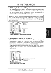
... sent to the motherboard and/or the CPU fan if these pins are not jumpers, do not place jumper caps over these pins. INST ALLATION Connectors R R +5Volt (Power Supply Stand By) Chassis Signal Ground P5A-B Chassis Open Alarm Lead ASUS P5A-B User's Manual 27 Depending on the fan manufacturer, the wiring and plug may occur...
... sent to the motherboard and/or the CPU fan if these pins are not jumpers, do not place jumper caps over these pins. INST ALLATION Connectors R R +5Volt (Power Supply Stand By) Chassis Signal Ground P5A-B Chassis Open Alarm Lead ASUS P5A-B User's Manual 27 Depending on the fan manufacturer, the wiring and plug may occur...

P5A-B User Manual
Page 28
...activity LED. After connecting the single end to the board, connect the two plugs at the other end to Pin 1 P5A-B IDE Connectors TIP: You may install one ribbon cable on the primary IDE connector and another on a SCSI drive and... 8. R III. INST ALLATION Connectors III. If you install two hard disks on the secondary IDE connector. IDELED P5A-B IDE Activity LED 28 ASUS P5A-B User's Manual BIOS now supports SCSI device or IDE CD-ROM bootup (see HDD Sequence SCSI/IDE First & ...Primary IDE Connector NOTE: Orient the red stripe on your cable to your hard disk for the jumper settings.
...activity LED. After connecting the single end to the board, connect the two plugs at the other end to Pin 1 P5A-B IDE Connectors TIP: You may install one ribbon cable on the primary IDE connector and another on a SCSI drive and... 8. R III. INST ALLATION Connectors III. If you install two hard disks on the secondary IDE connector. IDELED P5A-B IDE Activity LED 28 ASUS P5A-B User's Manual BIOS now supports SCSI device or IDE CD-ROM bootup (see HDD Sequence SCSI/IDE First & ...Primary IDE Connector NOTE: Orient the red stripe on your cable to your hard disk for the jumper settings.

P5A-B User Manual
Page 35
...do not see anything within 30 seconds from the time you need to enter BIOS setup. Recheck your jumper settings and connections or call your operating system. Be sure that is pressed. For ATX power supplies, ...III. Your monitor b. The power LED on test. Connect the power supply cord into a power outlet that all jumpers and connections are off your devices in some systems, marked with a surge protector. 5. You may have failed a... made, close the system case cover. 2. The system will light. ASUS P5A-B User's Manual 35 INSTALLATION Power Connection Procedures 1.
...do not see anything within 30 seconds from the time you need to enter BIOS setup. Recheck your jumper settings and connections or call your operating system. Be sure that is pressed. For ATX power supplies, ...III. Your monitor b. The power LED on test. Connect the power supply cord into a power outlet that all jumpers and connections are off your devices in some systems, marked with a surge protector. 5. You may have failed a... made, close the system case cover. 2. The system will light. ASUS P5A-B User's Manual 35 INSTALLATION Power Connection Procedures 1.

P5A-B User Manual
Page 63
... bootup. Photo sensor to detect intrusion by chassis mounted micro switches Using the ASUS CIDB 1. Connect the CIDB directly to the chassis connector or use the LDCM software or place a jumper on the chassis to use the contact method for triggering alarms. • ...short manually) the CLR jumper momentarily. 5. Check the hardware settings: • JP1 jumper should be enabled to use the photo sensor • MS1 and MS2 connectors should be connected to the chassis using a double-sided foam adhesive tape. CAUTION! ASUS P5A-B User's Manual 63 ASUS CIDB Connectors VI. VI...
... bootup. Photo sensor to detect intrusion by chassis mounted micro switches Using the ASUS CIDB 1. Connect the CIDB directly to the chassis connector or use the LDCM software or place a jumper on the chassis to use the contact method for triggering alarms. • ...short manually) the CLR jumper momentarily. 5. Check the hardware settings: • JP1 jumper should be enabled to use the photo sensor • MS1 and MS2 connectors should be connected to the chassis using a double-sided foam adhesive tape. CAUTION! ASUS P5A-B User's Manual 63 ASUS CIDB Connectors VI. VI...

P5A-B User Manual
Page 64
...and (5) is removed. Power is no power to the motherboard's intrusion memory. 64 ASUS P5A-B User's Manual SW: Enable/Disable chassis intrusion function in the motherboard ASUS CIDB Additional Considerations 1. When using the CIDB on these motherboards by providing a chassis ...jumper can be connected here to the motherboard's intrusion memory and buzzer. All motherboards with CIDB: If there is required to send a signal to trigger the chassis intrusion alarm. Motherboard with power removed. The CIDB can be used . ASUS CIDB Connectors VI. ASUS CIDB Setting up the ASUS...
...and (5) is removed. Power is no power to the motherboard's intrusion memory. 64 ASUS P5A-B User's Manual SW: Enable/Disable chassis intrusion function in the motherboard ASUS CIDB Additional Considerations 1. When using the CIDB on these motherboards by providing a chassis ...jumper can be connected here to the motherboard's intrusion memory and buzzer. All motherboards with CIDB: If there is required to send a signal to trigger the chassis intrusion alarm. Motherboard with power removed. The CIDB can be used . ASUS CIDB Connectors VI. ASUS CIDB Setting up the ASUS...

P5A-B User Manual
Page 65
... setting of "ASUS." ASUS LAN Card ASUS PCI-L101 Fast Ethernet Card LEDs VII. If you are using the ASUS PCI-L101 on an ASUS motherboard, leave the jumper on LAN (WOL) output signal to the motherboard's WOL_CON in order to display the LAN data activity. ASUS LAN Card Parts...feature of motherboard, set the jumper to "Other." Connect the LAN activity output signal (LAN_LED) to the system cabinet's front panel LAN_LED to utilize the wake on LAN Output Signal ASUS Motherboard type Other If you are using another brand of the motherboard. ASUS P5A-B User's Manual 65 VII...
... setting of "ASUS." ASUS LAN Card ASUS PCI-L101 Fast Ethernet Card LEDs VII. If you are using the ASUS PCI-L101 on an ASUS motherboard, leave the jumper on LAN (WOL) output signal to the motherboard's WOL_CON in order to display the LAN data activity. ASUS LAN Card Parts...feature of motherboard, set the jumper to "Other." Connect the LAN activity output signal (LAN_LED) to the system cabinet's front panel LAN_LED to utilize the wake on LAN Output Signal ASUS Motherboard type Other If you are using another brand of the motherboard. ASUS P5A-B User's Manual 65 VII...

