
P5A-B User Manual
Page 1
R P5A-B Pentium® Super7 Motherboard USER'S MANUAL
R P5A-B Pentium® Super7 Motherboard USER'S MANUAL

P5A-B User Manual
Page 4
... 45 Details of Chipset Features Setup 46 Power Management Setup 49 Details of Power Management Setup 49 PNP and PCI Setup 52 Details of the ASUS P5A-B Motherboard 11 III. CONTENTS I. INTRODUCTION 7 How this Manual is Organized 7 Item Checklist 7 II. Central Processing Unit (CPU 21 4. External Connectors 25 Power Connection Procedures 35 IV...
... 45 Details of Chipset Features Setup 46 Power Management Setup 49 Details of Power Management Setup 49 PNP and PCI Setup 52 Details of the ASUS P5A-B Motherboard 11 III. CONTENTS I. INTRODUCTION 7 How this Manual is Organized 7 Item Checklist 7 II. Central Processing Unit (CPU 21 4. External Connectors 25 Power Connection Procedures 35 IV...

P5A-B User Manual
Page 5
...Software Driver Support 66 Question and Answer 66 APPENDIX 67 Glossary 67 ASUS P5A-B User's Manual 5 ASUS CIDB 63 The ASUS CIDB Chassis Sensor 63 Using the ASUS CIDB 63 Setting up the ASUS CIDB 64 ASUS CIDB Additional Considerations 64 VII. CONTENTS Load BIOS Defaults 54 Load... 56 Save & Exit Setup 57 Exit Without Saving 57 V. SUPPORT SOFTWARE 59 ASUS Smart Motherboard Support CD 59 Desktop Management Interface (DMI 60 Introducing the ASUS DMI Configuration Utility 60 Starting the ASUS DMI Configuration Utility 60 Using the ASUS DMI Configuration Utility 61 VI.
...Software Driver Support 66 Question and Answer 66 APPENDIX 67 Glossary 67 ASUS P5A-B User's Manual 5 ASUS CIDB 63 The ASUS CIDB Chassis Sensor 63 Using the ASUS CIDB 63 Setting up the ASUS CIDB 64 ASUS CIDB Additional Considerations 64 VII. CONTENTS Load BIOS Defaults 54 Load... 56 Save & Exit Setup 57 Exit Without Saving 57 V. SUPPORT SOFTWARE 59 ASUS Smart Motherboard Support CD 59 Desktop Management Interface (DMI 60 Introducing the ASUS DMI Configuration Utility 60 Starting the ASUS DMI Configuration Utility 60 Using the ASUS DMI Configuration Utility 61 VI.

P5A-B User Manual
Page 7
...) PS/2 Mouse, Infrared, USB1, and USB2 external connector module (optional) ASUS PCI-L101 Wake-On-LAN 10/100 Ethernet Card (optional) ASUS P5A-B User's Manual 7 ASUS L101 Card Installation of the ASUS LAN card (optional) APPENDIX Glossary of Terms Item Checklist Check that your retailer. (1) ASUS Motherboard (2) 9-pin male serial external connector set (1) 25-pin female parallel...
...) PS/2 Mouse, Infrared, USB1, and USB2 external connector module (optional) ASUS PCI-L101 Wake-On-LAN 10/100 Ethernet Card (optional) ASUS P5A-B User's Manual 7 ASUS L101 Card Installation of the ASUS LAN card (optional) APPENDIX Glossary of Terms Item Checklist Check that your retailer. (1) ASUS Motherboard (2) 9-pin male serial external connector set (1) 25-pin female parallel...

P5A-B User Manual
Page 8
...PIO Modes 3 and 4 and Bus Master IDE DMA Mode 2, and supports Enhanced IDE devices, such as the ASUS PCI-L101 10/100 Fast Ethernet PCI card. • PC Health Monitoring (optional): Provides a convenient utility to...onboard PCI Bus Master IDE controller with special network cards, such as Tape Backup and CD-ROM drives. FEATURES ASUS P5A-B Motherboard • ALi AGPset: ALi® (Acer Laboratories Inc.) Aladdin V AGPset with EPP and ECP capabilities....; USB, PS/2 Mouse, IrDA Connector: Supports an optional cable and bracket set . 8 ASUS P5A-B User's Manual FEA TURES Features II. II.
...PIO Modes 3 and 4 and Bus Master IDE DMA Mode 2, and supports Enhanced IDE devices, such as the ASUS PCI-L101 10/100 Fast Ethernet PCI card. • PC Health Monitoring (optional): Provides a convenient utility to...onboard PCI Bus Master IDE controller with special network cards, such as Tape Backup and CD-ROM drives. FEATURES ASUS P5A-B Motherboard • ALi AGPset: ALi® (Acer Laboratories Inc.) Aladdin V AGPset with EPP and ECP capabilities....; USB, PS/2 Mouse, IrDA Connector: Supports an optional cable and bracket set . 8 ASUS P5A-B User's Manual FEA TURES Features II. II.
P5A-B User Manual
Page 9
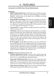
... prevent system overheat and system damage, the CPU fan and system fans are set for RPM and failure. FEATURES Introduction to ASUS Smart Series Motherboards Performance • SDRAM Optimized Performance: ASUS Smart Series motherboards support the new generation memory-Synchronous Dynamic Random Access Memory (SDRAM)-which can be used. • PC'98 Compliant: Both... satisfy all system components, and 32-bit device drivers and installation procedures for the future operating systems (OS) supporting OS Direct Power Management (OSPM) functionality. ASUS P5A-B User's Manual 9
... prevent system overheat and system damage, the CPU fan and system fans are set for RPM and failure. FEATURES Introduction to ASUS Smart Series Motherboards Performance • SDRAM Optimized Performance: ASUS Smart Series motherboards support the new generation memory-Synchronous Dynamic Random Access Memory (SDRAM)-which can be used. • PC'98 Compliant: Both... satisfy all system components, and 32-bit device drivers and installation procedures for the future operating systems (OS) supporting OS Direct Power Management (OSPM) functionality. ASUS P5A-B User's Manual 9
P5A-B User Manual
Page 10
... below a safe level. • Auto Fan Off: The system fans will prevent CPU damage from anywhere in one of system overheat. FEA TURES P5A-B Series II. Pushing the power button for more memory and hard drive space to the speed upon detection of two states, one is Sleep mode... automatically even in . II. FEATURES • Voltage Monitoring and Alert: System voltage levels are monitored to ensure stable current to the user. 10 ASUS P5A-B User's Manual With this benefit on managing their computer from system overheat. A simple glimpse provides useful information to critical...
... below a safe level. • Auto Fan Off: The system fans will prevent CPU damage from anywhere in one of system overheat. FEA TURES P5A-B Series II. Pushing the power button for more memory and hard drive space to the speed upon detection of two states, one is Sleep mode... automatically even in . II. FEATURES • Voltage Monitoring and Alert: System voltage levels are monitored to ensure stable current to the user. 10 ASUS P5A-B User's Manual With this benefit on managing their computer from system overheat. A simple glimpse provides useful information to critical...
P5A-B User Manual
Page 11
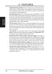
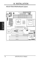
II. FEATURES Parts of the ASUS P5A-B Motherboard Serial Parallel 3 DIMM ALi Aladdin V Ports Port Sockets AGPset ATX Power AT Connector CPU ZIF Socket 7 Keyboard USB/MIR Floppy/IDE Connectors 512KB/1024KB Pipelined Burst L2 Cache Accelerated Graphics Port 3 PCI Slots 2 ISA Slots Programmable Flash ROM IrDA C-Media 3D Positional Sound Chip (optional) ASUS P5A-B User's Manual 11 FEA TURES Motherboard Parts II.
II. FEATURES Parts of the ASUS P5A-B Motherboard Serial Parallel 3 DIMM ALi Aladdin V Ports Port Sockets AGPset ATX Power AT Connector CPU ZIF Socket 7 Keyboard USB/MIR Floppy/IDE Connectors 512KB/1024KB Pipelined Burst L2 Cache Accelerated Graphics Port 3 PCI Slots 2 ISA Slots Programmable Flash ROM IrDA C-Media 3D Positional Sound Chip (optional) ASUS P5A-B User's Manual 11 FEA TURES Motherboard Parts II.
P5A-B User Manual
Page 12
III. INST ALLATION Motherboard Layout 12 ASUS P5A-B User's Manual INSTALLATION ASUS P5A-B Motherboard Layout AT Keyboard Connector KB USB, PS/2 Mouse, IrDA COM 1 COM 2 Parallel Port Row 5 4 3 2 1 0 VIO1 AT Power Connector VIO0 FS3 FS2 PWR_FAN FS1 FS0 ATX ...
III. INST ALLATION Motherboard Layout 12 ASUS P5A-B User's Manual INSTALLATION ASUS P5A-B Motherboard Layout AT Keyboard Connector KB USB, PS/2 Mouse, IrDA COM 1 COM 2 Parallel Port Row 5 4 3 2 1 0 VIO1 AT Power Connector VIO0 FS3 FS2 PWR_FAN FS1 FS0 ATX ...

P5A-B User Manual
Page 13
... (4-1 pins) 7) PRIMARY/SECOND.IDE p. 28 Primary/Secondary IDE Connector (40-1 pins) 8) IDELED p. 28 IDE LED Activity Light (2 pins) 9) ATX p. 29 ATX Motherboard Power Connector (20 pins) 10) PS/2 p. 29 AT Motherboard Power Connector (12 pins) 11) USB/MIR p. 31 USB, Infrared, PS/2 Mouse Module Connector (18-1 pins) 12) IR p. 31 IrDA-compliant... Connector (4 pins) *The onboard hardware monitor uses the address 290H-297H so legacy ISA cards must not use this address or else conflicts will occur. ASUS P5A-B User's Manual 13
... (4-1 pins) 7) PRIMARY/SECOND.IDE p. 28 Primary/Secondary IDE Connector (40-1 pins) 8) IDELED p. 28 IDE LED Activity Light (2 pins) 9) ATX p. 29 ATX Motherboard Power Connector (20 pins) 10) PS/2 p. 29 AT Motherboard Power Connector (12 pins) 11) USB/MIR p. 31 USB, Infrared, PS/2 Mouse Module Connector (18-1 pins) 12) IR p. 31 IrDA-compliant... Connector (4 pins) *The onboard hardware monitor uses the address 290H-297H so legacy ISA cards must not use this address or else conflicts will occur. ASUS P5A-B User's Manual 13
P5A-B User Manual
Page 14
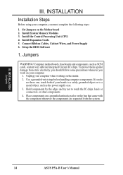
...motherboards, baseboards and components, such as the power supply case. 3. To protect them against damage from the system. Install the Central Processing Unit (CPU) 4. Jumpers WARNING! Unplug your hands to a safely grounded object or to touch the IC chips, leads or connectors, or other components. 4. INST ALLATION Jumpers 14 ASUS P5A... work on your computer, you do not have one, touch both of your computer when working on the Motherboard 2. Connect Ribbon Cables, Cabinet Wires, and Power Supply 6. Use a grounded wrist strap before handling computer components. Setup the BIOS Software...
...motherboards, baseboards and components, such as the power supply case. 3. To protect them against damage from the system. Install the Central Processing Unit (CPU) 4. Jumpers WARNING! Unplug your hands to a safely grounded object or to touch the IC chips, leads or connectors, or other components. 4. INST ALLATION Jumpers 14 ASUS P5A... work on your computer, you do not have one, touch both of your computer when working on the Motherboard 2. Connect Ribbon Cables, Cabinet Wires, and Power Supply 6. Use a grounded wrist strap before handling computer components. Setup the BIOS Software...

P5A-B User Manual
Page 17
...[2-3] [2-3] [1-2] [2-3] [2-3] [2-3] [1-2] [2-3] [1-2] [2-3] [1-2] [1-2] [2-3] [2-3] [1-2] [2-3] [2-3] [2-3] [1-2] [2-3] [2-3] [2-3] [1-2] [2-3] [2-3] [2-3] [2-3] [2-3] [2-3] [2-3] [1-2] [2-3] [2-3] [2-3] [1-2] [2-3] [2-3] [2-3] [2-3] [2-3] [2-3] [2-3] (Freq. ASUS P5A-B User's Manual 17 Mult.) BF0 BF1 BF2... [----] [2-3] [1-2] [----] [2-3] [1-2] [----] [2-3] [1-2] [2-3] *NOTE:The only IBM or Cyrix 6x86(L) (or M I) that is supported on this motherboard is revision 2.7 or later (see next page). INSTALLATION Set the jumpers by the Internal speed of your CPU as follows: CPU Model Freq.
...[2-3] [2-3] [1-2] [2-3] [2-3] [2-3] [1-2] [2-3] [1-2] [2-3] [1-2] [1-2] [2-3] [2-3] [1-2] [2-3] [2-3] [2-3] [1-2] [2-3] [2-3] [2-3] [1-2] [2-3] [2-3] [2-3] [2-3] [2-3] [2-3] [2-3] [1-2] [2-3] [2-3] [2-3] [1-2] [2-3] [2-3] [2-3] [2-3] [2-3] [2-3] [2-3] (Freq. ASUS P5A-B User's Manual 17 Mult.) BF0 BF1 BF2... [----] [2-3] [1-2] [----] [2-3] [1-2] [----] [2-3] [1-2] [2-3] *NOTE:The only IBM or Cyrix 6x86(L) (or M I) that is supported on this motherboard is revision 2.7 or later (see next page). INSTALLATION Set the jumpers by the Internal speed of your CPU as follows: CPU Model Freq.
P5A-B User Manual
Page 18
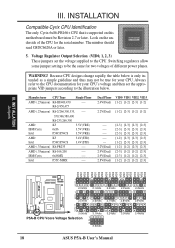
... VID1 VID2 VID3 VID0 VID1 VID2 VID3 1 2 3 2.0Volts 2.1Volts 1 2 3 2.5Volts 2.6Volts 1 2 3 3.0Volts 3.1Volts P5A-B CPU Vcore Voltage Selection 1 2 3 3.5Volts 2.2Volts 2.7Volts 3.2Volts 2.3Volts 2.8Volts 3.3Volts 2.4Volts 2.9Volts 3.4Volts 18 ASUS P5A-B User's Manual III. IBM/Cyrix 6x86MX ---- Look on this motherboard must be Revision 2.7 or later. WARNING! Dual Plane VID0 VID1 VID2 VID3 2.4V...
... VID1 VID2 VID3 VID0 VID1 VID2 VID3 1 2 3 2.0Volts 2.1Volts 1 2 3 2.5Volts 2.6Volts 1 2 3 3.0Volts 3.1Volts P5A-B CPU Vcore Voltage Selection 1 2 3 3.5Volts 2.2Volts 2.7Volts 3.2Volts 2.3Volts 2.8Volts 3.3Volts 2.4Volts 2.9Volts 3.4Volts 18 ASUS P5A-B User's Manual III. IBM/Cyrix 6x86MX ---- Look on this motherboard must be Revision 2.7 or later. WARNING! Dual Plane VID0 VID1 VID2 VID3 2.4V...
P5A-B User Manual
Page 19
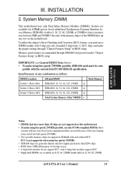
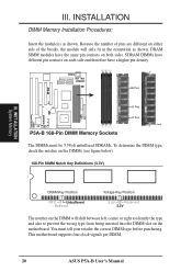
..., 128MB, or 256MB to form a memory size between 8MB and 768MB. INSTALLATION 2. patible with memory chips) of the DIMM takes up one row on this motherboard. • To make using bus speeds ≥83MHz . • SDRAM chips are generally thinner and have more than EDO chips. • BIOS shows SDRAM... Intel PC100 SDRAM specification. Memory speed setup is not supported when using bus speeds ≥95MHz possible, use a DIMM module with and without ECC. ASUS P5A-B User's Manual 19 System Memory (DIMM) This motherboard uses only Dual Inline Memory Modules (DIMMs).
..., 128MB, or 256MB to form a memory size between 8MB and 768MB. INSTALLATION 2. patible with memory chips) of the DIMM takes up one row on this motherboard. • To make using bus speeds ≥83MHz . • SDRAM chips are generally thinner and have more than EDO chips. • BIOS shows SDRAM... Intel PC100 SDRAM specification. Memory speed setup is not supported when using bus speeds ≥95MHz possible, use a DIMM module with and without ECC. ASUS P5A-B User's Manual 19 System Memory (DIMM) This motherboard uses only Dual Inline Memory Modules (DIMMs).
P5A-B User Manual
Page 20
...have the same pin contacts on the DIMMs (see figure below). 168-Pin DIMM Notch Key Definitions (3.3V) R III. This motherboard supports four clock signals per DIMM. 20 ASUS P5A-B User's Manual You must be 3.3Volt unbuffered SDRAMs. To determine the DIMM type, check the notches on both sides. DRAM ...SIMM modules have a higher pin density. 88 Pins 60 Pins 20 Pins Lock P5A-B 168-Pin DIMM Memory Sockets The DIMMs must...
...have the same pin contacts on the DIMMs (see figure below). 168-Pin DIMM Notch Key Definitions (3.3V) R III. This motherboard supports four clock signals per DIMM. 20 ASUS P5A-B User's Manual You must be 3.3Volt unbuffered SDRAMs. To determine the DIMM type, check the notches on both sides. DRAM ...SIMM modules have a higher pin density. 88 Pins 60 Pins 20 Pins Lock P5A-B 168-Pin DIMM Memory Sockets The DIMMs must...
P5A-B User Manual
Page 21
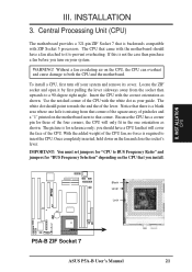
...of the four corners, the CPU will cover the face of the CPU with the motherboard should have a CPU fan that is for "BUS Frequency Selection" depending on your system. Blank Lever Lock R P5A-B ZIF Socket 7 ASUS P5A-B User's Manual 21 If this is not the case then purchase a fan before you...To install a CPU, first turn on the CPU that you should point towards the end the of pin holes and a "1" printed on the motherboard next to that there is a blank area where one orientation as shown. The picture is backwards compatible with the correct orientation as shown. Locate the...
...of the four corners, the CPU will cover the face of the CPU with the motherboard should have a CPU fan that is for "BUS Frequency Selection" depending on your system. Blank Lever Lock R P5A-B ZIF Socket 7 ASUS P5A-B User's Manual 21 If this is not the case then purchase a fan before you...To install a CPU, first turn on the CPU that you should point towards the end the of pin holes and a "1" printed on the motherboard next to that there is a blank area where one orientation as shown. The picture is backwards compatible with the correct orientation as shown. Locate the...

P5A-B User Manual
Page 23
... of them are in "My Computer," contains a "System" icon, which leaves 6 free for your motherboard and expansion cards. Both ISA and PCI expansion cards may cause severe damage to operate. INSTALLATION 4. Replace the computer system's cover. 8. ASUS P5A-B User's Manual 23 Double clicking on your computer will experience problems when those two devices...
... of them are in "My Computer," contains a "System" icon, which leaves 6 free for your motherboard and expansion cards. Both ISA and PCI expansion cards may cause severe damage to operate. INSTALLATION 4. Replace the computer system's cover. 8. ASUS P5A-B User's Manual 23 Double clicking on your computer will experience problems when those two devices...

P5A-B User Manual
Page 24
...process, this motherboard complies with the...cards after those IRQs and DMAs you want to avail of the motherboard's AGP features. The PCI and PNP configuration of the BIOS setup...PCI slot that has a card in it that the jumpers on this motherboard use this motherboard are assigned automatically from those available. DMA assignments for those used by...Expansion Cards III. For PNP cards, IRQs are handled the same way as an ASUS 3D Hardware Accelerator. An IRQ number is added to set to use a DMA... Port This motherboard provides an accelerated graphics port (AGP) slot to support a new ...
...process, this motherboard complies with the...cards after those IRQs and DMAs you want to avail of the motherboard's AGP features. The PCI and PNP configuration of the BIOS setup...PCI slot that has a card in it that the jumpers on this motherboard use this motherboard are assigned automatically from those available. DMA assignments for those used by...Expansion Cards III. For PNP cards, IRQs are handled the same way as an ASUS 3D Hardware Accelerator. An IRQ number is added to set to use a DMA... Port This motherboard provides an accelerated graphics port (AGP) slot to support a new ...
P5A-B User Manual
Page 25
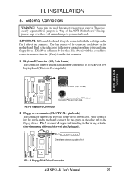
...Some pins are labeled on the other end to the floppy drives. (Pin 5 is the side closest to Pin 1 R R P5A-B Floppy Disk Drive Connector ASUS P5A-B User's Manual 25 Pin 1 Orient the red stripe on hard drives and some floppy drives. III. The four corners of the...your cable to the power connector on your motherboard. P5A-B Keyboard Connector 2. INST ALLATION Connectors III. Pin 1 is removed to the board, connect the two plugs on the motherboard. After connecting the single end to prevent inserting in "Map of the ASUS Motherboard." IDE ribbon cable must be connected with...
...Some pins are labeled on the other end to the floppy drives. (Pin 5 is the side closest to Pin 1 R R P5A-B Floppy Disk Drive Connector ASUS P5A-B User's Manual 25 Pin 1 Orient the red stripe on hard drives and some floppy drives. III. The four corners of the...your cable to the power connector on your motherboard. P5A-B Keyboard Connector 2. INST ALLATION Connectors III. Pin 1 is removed to the board, connect the two plugs on the motherboard. After connecting the single end to prevent inserting in "Map of the ASUS Motherboard." IDE ribbon cable must be connected with...
P5A-B User Manual
Page 27
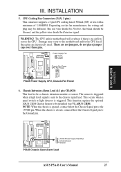
... Connectors R R +5Volt (Power Supply Stand By) Chassis Signal Ground P5A-B Chassis Open Alarm Lead ASUS P5A-B User's Manual 27 Depending on the fan manufacturer, the wiring and plug may occur to the Ground pin. The CPU and/or motherboard will overheat if there is closed, connect/short the Chassis Signal pin... to the motherboard and/or the CPU fan if these ...
... Connectors R R +5Volt (Power Supply Stand By) Chassis Signal Ground P5A-B Chassis Open Alarm Lead ASUS P5A-B User's Manual 27 Depending on the fan manufacturer, the wiring and plug may occur to the Ground pin. The CPU and/or motherboard will overheat if there is closed, connect/short the Chassis Signal pin... to the motherboard and/or the CPU fan if these ...


